US1574499A - Cushion tire - Google Patents
Cushion tire Download PDFInfo
- Publication number
- US1574499A US1574499A US16380A US1638025A US1574499A US 1574499 A US1574499 A US 1574499A US 16380 A US16380 A US 16380A US 1638025 A US1638025 A US 1638025A US 1574499 A US1574499 A US 1574499A
- Authority
- US
- United States
- Prior art keywords
- tire
- voids
- void
- opposed
- tread
- Prior art date
- Legal status (The legal status is an assumption and is not a legal conclusion. Google has not performed a legal analysis and makes no representation as to the accuracy of the status listed.)
- Expired - Lifetime
Links
Images
Classifications
-
- B—PERFORMING OPERATIONS; TRANSPORTING
- B60—VEHICLES IN GENERAL
- B60C—VEHICLE TYRES; TYRE INFLATION; TYRE CHANGING; CONNECTING VALVES TO INFLATABLE ELASTIC BODIES IN GENERAL; DEVICES OR ARRANGEMENTS RELATED TO TYRES
- B60C7/00—Non-inflatable or solid tyres
- B60C7/10—Non-inflatable or solid tyres characterised by means for increasing resiliency
- B60C7/107—Non-inflatable or solid tyres characterised by means for increasing resiliency comprising lateral openings
Definitions
- the present invention relates specifically,
- the feature voids comprise a deep lateral projection 13 vented at one end only in a longitudinally directed recess portion 12.
- the voided areas (the composite openings -1213) shall constitute a balanced mechanical condition Within the mass, they have been arranged as reversed Us on opposed sides of the tire so thatthe projected limits of any opposed pair will coincide in the longitudinal dimension. Also the opposed voids have been arranged to lie substantially within the same horizontal plane.
- a resilient tire comprising; a plurality o'fvoids arranged in opposite symmetrical pairs in-the opposed sides of-the tire; each said void in plan View “constituting a laterally deeply penetrating element and a circumferentially directed orifice portion recessed into the side wall, the two portions thereof forming an L-shaped figure with said figures'in opposed and reversed relation on opposite sides of the tire.
- a resilient tire having symmetrically arranged opposed stress relieving voids below the plane-of the tread portion, each of said voids in plan view forming an L- shaped contour, the inner leg forming a laterally deep sub-tread void and the outer leg a circumferentially extensive reentrant groove in a side Wall, said'figures arranged in opposed pairs with the figures L reversed and non-contacting.
Landscapes
- Engineering & Computer Science (AREA)
- Mechanical Engineering (AREA)
- Tires In General (AREA)
Description
L a 9 an H 8 ST... mmm Mm c m T F vi .I in y X 1 V a I rim/ms 6. #105,911; INVENTOR- ATTORNEY.
Patented Feb. 23, 1926.
UNITED STATES PATENT OFFICE.
THOMAS C. MARSHALL, OF 'MOUNT SAVAGE, MARYLAND, ASSIGNQE TO KELLY-- T5 CUMBERLAND, MARYLAND, A CORPORATION SI-RINGFIELD TIRE COMPANY, OF NEW JERSEY.
CUSHION TIRE.
Application filed lvlarch 18, 1925. Serial No. 16,380.
To all whom it may concern.-
Be it known that I, TnoMAs C. MARSHALL, a citizen of the United States, residing'at h Iount Savage, in the county of Allegany and State of Maryland, have invented certain new and useful Improvements in Cushion Tires, of which the following is asp'eoification.
This invention has for its object the improvement of the so-called cushion tire; being a resilient rubber structure of the nonpneumatic type dependent for its resillency, in part, upon the inherent property of the rubber compound, and in part upon certain forms of stress relieving void spaces incorporated into the internal area thereof.
It is well known, and an ancient expedient in this art, to provide various types of void spaces extending from the tire sides within the mass structure. Also it is similarly old to provide variously designed recessed areas along the sides of the structure; independent of, or in conjunction with voids of considerable extent directed laterally of the tire and carried to varying depth within the mass and below the tread.
The present invention relates specifically,
to a cushion tire having extensive sub-tread voids, worked in special relationship with longitudinally extensive surface recesses in the tire sides, the object being to so proportion and relate the main voids and the side recesses that the resilient properties of the tire shall be developed to the maximum effectiveness consistent with the weight-bearing requirements, and to accomplish this, and other desirable objects more specifically developed within the specification, by the novel means disclosed and in a manner conducive to economy of manufacture.
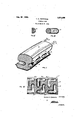
In the drawing:
Fig. I, is a cross section and partial perspective of a portion of a tire embodying the invention.
Fig. II, is a section through 2-2 of Fig. IV, showing a void forming molding appliance for creating a portion of the longitudinal recess.
Fig. III, is a section through 33 of Fig. IV, showing that portion of the molding appliance adapted to form the lateral recess.
Fig. IV, is a longitudinal section through the plane of the voided area. The molding appliances used for forming the voids, while no part of the invention, are shown still embedded within the tire, but are, of course,
-The feature voids comprise a deep lateral projection 13 vented at one end only in a longitudinally directed recess portion 12.
In order to relieve the internal mass of as much material as is possible, the deep voids 13 have been directed toward the center of the structure, alternately from each side in staggered relationship; the internal terminii of each opposed void extending beyond the median plane of the structure (as clearly indicated in Fig. IV). This disposition effectively breaking up the circumferential wave, or fiowjof the internal mass when the tire-is in use; dissipates the heat of internal friction,'and leaves a sufficient intact transverse area between adjacent voids to impart lateral stability to the tire. The circumferentially extensive portions 12, of these voids constitute a weakened recessed zone substantially under the outer "it to the duty for which designed. Preferably, the extent of the recesses 12, circumferentially, is considerably greater than that of the intermediate abutments 15. For certain purposes, where consideration of lateral stability is not a controlling condition, these recesses 12 may be substantially merged into each other to the virtual elimination of the abutments 15.
In order that the voided areas, (the composite openings -1213) shall constitute a balanced mechanical condition Within the mass, they have been arranged as reversed Us on opposed sides of the tire so thatthe projected limits of any opposed pair will coincide in the longitudinal dimension. Also the opposed voids have been arranged to lie substantially within the same horizontal plane.
The above proportions and arrangements are considered the most desirable, but are not stated as specific limitations upon the obvious variations that may be resorted to in orderthat substantially the same objective may be attained by reso'rting to variations within the lawful range of equivalents to which the invention may be entitled.
Having thus tullydisc'losed a preferred form for practicing this invention, what I claim is 1. ,A resilient tire comprising; a plurality of voids arranged in symmetrical pairs in the opposed sides of the tire; each said void in plan View constituting a laterally deeply penetrating element and acircumierenti'ally directed orificeport'ion recessed into the side wall, the two portions thereof forming an L-shapedifigure.
2. A resilient tire comprising; a plurality o'fvoids arranged in opposite symmetrical pairs in-the opposed sides of-the tire; each said void in plan View "constituting a laterally deeply penetrating element and a circumferentially directed orifice portion recessed into the side wall, the two portions thereof forming an L-shaped figure with said figures'in opposed and reversed relation on opposite sides of the tire. I
3. A resilient tire having in each side wall a series of circumferentially extensive reentrant voids arranged in opposite symmetricalpairs, each-said void further characterized by a laterally deep sub-tread void originating at one extremity thereof and extending toward the centerio'f the tire without contact with a similar complemental opposed extension.
.4. A resilient .tirehavingin eachside Wall a .series of circumferentially extensive reentrant voids arranged in directlyopposed symmetrical pairs, each said void further characterizedby a laterally deep sub-tread void originating at one extremity thereof and extending laterally of the tire at least to the central plane thereof, in non-conflicting relation with a similar. complemental opposed extension.
5. A resilient tire havinga circumferentiai zone of weakness inthe side Walls substantially below the outer tread edges in the form of a substantially 'continuous'series of reentrant grooves, a spaced series of opposed laterally deep sub-tread voids extending partially through'the said tire in non-communicating relation, each sub-tread void vented, respectively, into the sidewalls at an extremity of'one said reentrantgroove.
6. A resilient tire having symmetrically arranged opposed stress relieving voids below the plane-of the tread portion, each of said voids in plan view forming an L- shaped contour, the inner leg forming a laterally deep sub-tread void and the outer leg a circumferentially extensive reentrant groove in a side Wall, said'figures arranged in opposed pairs with the figures L reversed and non-contacting.
7. A resilient tirehaving a circumferential zone of Weakness in the side walls comprising a series of closely spaced longitudinally elongated reentrant grooves separated bynarrow abutments merging with normal contour of the said side walls, a spaced series of laterally deep sub-tread voids each said void vented alternately on opposite sides of said tire into one of said grooves.
In testimony whereof I aflix my'si'gnature.
THOMAS C. MARSHALL.
Priority Applications (1)
| Application Number | Priority Date | Filing Date | Title |
|---|---|---|---|
| US16380A US1574499A (en) | 1925-03-18 | 1925-03-18 | Cushion tire |
Applications Claiming Priority (1)
| Application Number | Priority Date | Filing Date | Title |
|---|---|---|---|
| US16380A US1574499A (en) | 1925-03-18 | 1925-03-18 | Cushion tire |
Publications (1)
| Publication Number | Publication Date |
|---|---|
| US1574499A true US1574499A (en) | 1926-02-23 |
Family
ID=21776826
Family Applications (1)
| Application Number | Title | Priority Date | Filing Date |
|---|---|---|---|
| US16380A Expired - Lifetime US1574499A (en) | 1925-03-18 | 1925-03-18 | Cushion tire |
Country Status (1)
| Country | Link |
|---|---|
| US (1) | US1574499A (en) |
Cited By (3)
| Publication number | Priority date | Publication date | Assignee | Title |
|---|---|---|---|---|
| EP0028350A1 (en) * | 1979-11-02 | 1981-05-13 | Bayer Ag | Rubber cushion tyre and process for its manufacture |
| US7481498B1 (en) * | 2005-10-17 | 2009-01-27 | Geo Plastics | Injection-molded wheel having a plurality of recesses in a rim portion |
| US20220355624A1 (en) * | 2019-11-10 | 2022-11-10 | Galileo Wheel Ltd. | Run-flat and airless tires |
-
1925
- 1925-03-18 US US16380A patent/US1574499A/en not_active Expired - Lifetime
Cited By (4)
| Publication number | Priority date | Publication date | Assignee | Title |
|---|---|---|---|---|
| EP0028350A1 (en) * | 1979-11-02 | 1981-05-13 | Bayer Ag | Rubber cushion tyre and process for its manufacture |
| US7481498B1 (en) * | 2005-10-17 | 2009-01-27 | Geo Plastics | Injection-molded wheel having a plurality of recesses in a rim portion |
| US20220355624A1 (en) * | 2019-11-10 | 2022-11-10 | Galileo Wheel Ltd. | Run-flat and airless tires |
| US12220952B2 (en) * | 2019-11-10 | 2025-02-11 | Galileo Wheel Ltd. | Run-flat and airless tires |
Similar Documents
| Publication | Publication Date | Title |
|---|---|---|
| US4078596A (en) | Highly durable tread pattern of a rib type pneumatic tire | |
| KR100450271B1 (en) | Motor-vehicle pneumatic type having a tread pattern particularly appropriate for running on snow-covered road surfaces | |
| KR100846166B1 (en) | Wide tread tires for vehicles, especially for snow-covered ground | |
| RU2472634C1 (en) | Air tire | |
| US3405753A (en) | Pneumatic tire treads | |
| US3844326A (en) | Heavy construction vehicle tires | |
| JP6092059B2 (en) | Pneumatic tire | |
| GB577521A (en) | Improvements in tyres for vehicles | |
| US1574499A (en) | Cushion tire | |
| US9840116B2 (en) | Pneumatic tire | |
| KR101357513B1 (en) | tire | |
| JPH0326964Y2 (en) | ||
| US6527023B1 (en) | Pneumatic radial tire including sipes | |
| CN110709260A (en) | Pneumatic tire | |
| JP6949649B2 (en) | tire | |
| US1946209A (en) | Traction tread | |
| JP2015089719A (en) | Pneumatic tire | |
| US20040134580A1 (en) | Tyre for a vehicle wheel including specific tread patterns | |
| US2479958A (en) | Tire tread | |
| JPS63195006A (en) | Pneumatic tire | |
| US1594965A (en) | Heel | |
| US2034811A (en) | Resilient tire | |
| US1861276A (en) | Pneumatic tire | |
| JP3190836U (en) | Winter tires | |
| US1360907A (en) | ernenwein |