US1574495A - Beverage dispenser - Google Patents
Beverage dispenser Download PDFInfo
- Publication number
- US1574495A US1574495A US54979A US5497925A US1574495A US 1574495 A US1574495 A US 1574495A US 54979 A US54979 A US 54979A US 5497925 A US5497925 A US 5497925A US 1574495 A US1574495 A US 1574495A
- Authority
- US
- United States
- Prior art keywords
- cup
- base
- dispenser
- bottle
- ribs
- Prior art date
- Legal status (The legal status is an assumption and is not a legal conclusion. Google has not performed a legal analysis and makes no representation as to the accuracy of the status listed.)
- Expired - Lifetime
Links
Images
Classifications
-
- B—PERFORMING OPERATIONS; TRANSPORTING
- B67—OPENING, CLOSING OR CLEANING BOTTLES, JARS OR SIMILAR CONTAINERS; LIQUID HANDLING
- B67D—DISPENSING, DELIVERING OR TRANSFERRING LIQUIDS, NOT OTHERWISE PROVIDED FOR
- B67D3/00—Apparatus or devices for controlling flow of liquids under gravity from storage containers for dispensing purposes
- B67D3/0029—Apparatus or devices for controlling flow of liquids under gravity from storage containers for dispensing purposes provided with holders for bottles or similar containers
Definitions
- This invention relates to improvements in beverage dispensers and particularly to that class of devices commonly known in the trade as syrup dispensers, wherein a quantity of syrup 'is to be withdrawn and mixed in a glass or other receptacle with water or carbonated water.
- Syrups are usually marketed in bottles preferably of one gallon size and devices have heretofore been provided on which these bottles are positioned in inverted position so that the syrup may run out of them and then be withdrawn or dispensed.
- These devices are usually formed of metal or other opaque material such as porcelain and when ever made ofglass or similar transparent 5 material they have been found undesirable for the reason that they are unsightly in ap-,
- An object of this invention is to provide a syrup dispenser which is formed of glass or similar transparent material and which is so constructed as to be sightly in appearance, the dispenser being so constructed as to have light refracting parts.
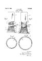
- Figure 1 is a side elevation of the-improved beverage dispenser, the bottle being :zlliown as applied thereto.
- Fig. 2 a vertical section through the beverage dispenser.
- Fig. 8 is a horizontal section taken substantially upon the line 3-3 of Fig. 1.
- Fig. 4 is a horizontal section taken substantially on the line 44 of Fig. 1.
- the improved beveragedispenser consists of a hollow base 10, preferably frusto conical in form. Integral with this base and on top thereof there is formed an open topped cup 11..
- the bottle is adapted to be positioned in inverted position on the cup 11, having its neck extending downwardly into the cup.
- the primary object of the invention is to so form the dispenser that these undesirable features will be eliminated; consequently on the interior of the cup 1].
- vertical ribs or corrugations 16 are formed, andon the outside of the cup horizontal ribs or co1.'ruga tions 17 are formed.
- the ribs 16 extend from the top to the bottom of the cup but the horizontal ribs 17 are arranged only from the normal level of the fluid within the cup to its rim.
- the bottom 18 of the cup 11 is concave convex in form so as to present the appearance of being dished.
- vertical ribs 19 extending from approximately the top to the bottom of the base and on the outside of the base there are formed horizontal ribs 20.
- the syrup upon flowing from the bottle to the interior of the cup will have its level rise only to the neck of the bottle andthe colored syrup can be readily seen through the transparentwalls of the cup 11, below the horizontal ribs 17.
- the horizontal ribs 17 and the vertical ribs 16 cooperate to form light refracting prisms, preventing anyone from seeing the neck of the bottle within the cup and -'and :20 also tend to produce a scintillating efiect upon the dispensers.
- a beverage dispenser comprising a base. formed of transparent material, an open topped cup formed integral with the base on which a bottle is adapted to rest in an inverted position. a faucet for withdrawing liquid from said cup, said cup having its side walls ribbed or roughened to provide a light refracting means as and for the purposes described.
- a beverage dispenser comprising a base termed of transparent material, an open topped cup formedintegral with the base on which a bottle is adapted to rest in an inverted position, a faucet for withdrawing liquid from said cup, said cup and base having their side walls roughened to provide a light retracting means as and for the purposes described.
- A-heveragc dispenser comprising-a base formed of transparent material, an open opped cup formed integral with the base on which a bottle is adapted to rest in an inverted position, a faucet for withdrawing liquid from said cup, there being vertical ribs formed upon the interior surface of the cup and horizontal ribs formed upon the exterior surface of the cup providinga light retracting means as and for the purpose described.
- a beverage dispenser comprising a base formed of transparent material, an open topped cup formed integral with the base on which a bottle is adapted to rest in an inverted position. a faucet for withdrawing liquid from said cup, there being vertical ribs formed upon the interior surface of the base and horizontal ribs formed upon the exterior surface thereof to provide a light retracting means as and for the purpose described.
- a beverage dispenser comprising a 'frusto conical base and an open topped cup formed integral therewith. said base and cup being formed of glass or similar transparent material and means for withdrawing liquid from said cup.
- a beverage dispenser comprising a t'rnsto conical base and an open topped cup termed integral therewith, said base and cup being formed of glass or similar transparent n-aterial.
- means for withdrawing liquid from said cup there being a groove formed in the bottom of the base and a resilient material, and means for withdrawing liquid from said cup, said cup having a dished bottom as and for the purpose described.
Description
Feb. 23 1926.
C. A. LOOK BEVERAGE DISPENSER Filed Sept. 83,
Inventor.
Carrol a. Look. Bey
Patented Feb. 23, 1926.
UNITED STATES PATENT OFFICE.
BEVERAGE nxsPENsEn.
Application filed September 8, 1925. Serial No. 54,979.
To all whom it may concern: 4
Be it known that I, CARROL A. LOOK, :1 citizen of the United States, residing at Los Angeles, in the county ofLos Angelcs 5 and State of California, have invented new and useful Improvements in Beverage Dispensers, of which the following is a specification.
This invention relates to improvements in beverage dispensers and particularly to that class of devices commonly known in the trade as syrup dispensers, wherein a quantity of syrup 'is to be withdrawn and mixed in a glass or other receptacle with water or carbonated water.
Syrups are usually marketed in bottles preferably of one gallon size and devices have heretofore been provided on which these bottles are positioned in inverted position so that the syrup may run out of them and then be withdrawn or dispensed. These devices are usually formed of metal or other opaque material such as porcelain and when ever made ofglass or similar transparent 5 material they have been found undesirable for the reason that they are unsightly in ap-,
pearance.
An object of this invention is to provide a syrup dispenser which is formed of glass or similar transparent material and which is so constructed as to be sightly in appearance, the dispenser being so constructed as to have light refracting parts.
' With the foregoing and other objects in view which will be made manifest from the following detail description and specifically pointed out in the appended claims, reference i-s had to the accompanying drawings an illustrative embodiment of the invention, wherein;
Figure 1 is a side elevation of the-improved beverage dispenser, the bottle being :zlliown as applied thereto.
Fig. 2 a vertical section through the beverage dispenser.
Fig. 8 is a horizontal section taken substantially upon the line 3-3 of Fig. 1.
Fig. 4 is a horizontal section taken substantially on the line 44 of Fig. 1.
Referring to the accompanying drawings, wherein similar characters designate slmilar parts throughout, the improved beveragedispenser consists of a hollow base 10, preferably frusto conical in form. Integral with this base and on top thereof there is formed an open topped cup 11.. The bottle is adapted to be positioned in inverted position on the cup 11, having its neck extending downwardly into the cup. On the upper edge of the cup 11, which is somewhat thickened, there is formed a concaved recess 12 and a rubber gasket or protector 13, is positioned therein. This gasket 13,
desirable for the following reasons:
As the syrup flows out of the bottle B into the cup 11, it will be maintained at a height which is even with the lower end of the neck of the bottle, as the glass is transparent it will be readily visible and also the neck of the bottle could be seen through the walls of the cup. Furthermore, if the base 10 was formed of transparent glass, anyone could readily see through it which would detract from the appearance of the dispenser.
The primary object of the invention is to so form the dispenser that these undesirable features will be eliminated; consequently on the interior of the cup 1]., vertical ribs or corrugations 16 are formed, andon the outside of the cup horizontal ribs or co1.'ruga tions 17 are formed. The ribs 16 extend from the top to the bottom of the cup but the horizontal ribs 17 are arranged only from the normal level of the fluid within the cup to its rim. The bottom 18 of the cup 11 is concave convex in form so as to present the appearance of being dished. On the interior of the base 10 there are formed vertical ribs 19 extending from approximately the top to the bottom of the base and on the outside of the base there are formed horizontal ribs 20.
By the improved construction the syrup upon flowing from the bottle to the interior of the cup will have its level rise only to the neck of the bottle andthe colored syrup can be readily seen through the transparentwalls of the cup 11, below the horizontal ribs 17. Above the lower end of the neck of the bottle B the horizontal ribs 17 and the vertical ribs 16 cooperate to form light refracting prisms, preventing anyone from seeing the neck of the bottle within the cup and -'and :20 also tend to produce a scintillating efiect upon the dispensers.
In actual prattice a dispenser so formed produces a very neat and attractive effect over the opaque dispensers heretofore pro- .vided. It will be readily appreciated that in producing the light retracting prisms the particular arrangement, of corrugations shown is not necessary, other forms of corrugations or strippling could be employed. However, the arrangement of the ribs shown is'preferably used for the reason that in washing the dispenser a wash rag could be drawn vertically from the interior surfaces of the cup and the base and will clean the dispenser between the ribs. In cleaning the outside of the dispenser. the wash rag is merely moved about the dispenser in a horizontal manner and will clean the device between the ribs.
As these devices are frequently mounted on marble soda fountains and the like, it is also an object of the invention to provide a protecting means for the bottom of the device so that the lower edge of the base will not become chipped or scratch the foun=- tain. Consequently there is provided a groove 21 in the'bottom of the base and a rubber protector 22 has a web 23 extending upwardly into the groove. On the bottom of the web there is provided outwardly extending flanges 24 and 25 which extend beneath the, bottom of the base. The form of the protector is such that it will maintain itself on the bottom of the base and will not drop 03 while the dispenser is being rroved fromplace to place.
From the above described construction it will be appreciated that an improved form of beverage or syrup dispenser is provided v'hich has many advantages over constructions heretofore manufactured. W
Various changes may be made in the details of construction without departing from the spirit or scope of the invention as defined by the appended claims.
What I claim is: r
1. A beverage dispenser comprising a base. formed of transparent material, an open topped cup formed integral with the base on which a bottle is adapted to rest in an inverted position. a faucet for withdrawing liquid from said cup, said cup having its side walls ribbed or roughened to provide a light refracting means as and for the purposes described.
2. A beverage dispenser comprising a base termed of transparent material, an open topped cup formedintegral with the base on which a bottle is adapted to rest in an inverted position, a faucet for withdrawing liquid from said cup, said cup and base having their side walls roughened to provide a light retracting means as and for the purposes described. v
3. A-heveragc dispenser comprising-a base formed of transparent material, an open opped cup formed integral with the base on which a bottle is adapted to rest in an inverted position, a faucet for withdrawing liquid from said cup, there being vertical ribs formed upon the interior surface of the cup and horizontal ribs formed upon the exterior surface of the cup providinga light retracting means as and for the purpose described.
4. A beverage dispenser comprising a base formed of transparent material, an open topped cup formed integral with the base on which a bottle is adapted to rest in an inverted position. a faucet for withdrawing liquid from said cup, there being vertical ribs formed upon the interior surface of the base and horizontal ribs formed upon the exterior surface thereof to provide a light retracting means as and for the purpose described.
"5. A beverage dispenser comprising a 'frusto conical base and an open topped cup formed integral therewith. said base and cup being formed of glass or similar transparent material and means for withdrawing liquid from said cup.
6. A beverage dispenser comprising a t'rnsto conical base and an open topped cup termed integral therewith, said base and cup being formed of glass or similar transparent n-aterial. means for withdrawing liquid from said cup, there being a groove formed in the bottom of the base and a resilient material, and means for withdrawing liquid from said cup, said cup having a dished bottom as and for the purpose described.
In testimony whereof I have signed my name to this specification.
C. A. LOOK.
Priority Applications (1)
| Application Number | Priority Date | Filing Date | Title |
|---|---|---|---|
| US54979A US1574495A (en) | 1925-09-08 | 1925-09-08 | Beverage dispenser |
Applications Claiming Priority (1)
| Application Number | Priority Date | Filing Date | Title |
|---|---|---|---|
| US54979A US1574495A (en) | 1925-09-08 | 1925-09-08 | Beverage dispenser |
Publications (1)
| Publication Number | Publication Date |
|---|---|
| US1574495A true US1574495A (en) | 1926-02-23 |
Family
ID=21994770
Family Applications (1)
| Application Number | Title | Priority Date | Filing Date |
|---|---|---|---|
| US54979A Expired - Lifetime US1574495A (en) | 1925-09-08 | 1925-09-08 | Beverage dispenser |
Country Status (1)
| Country | Link |
|---|---|
| US (1) | US1574495A (en) |
Cited By (9)
| Publication number | Priority date | Publication date | Assignee | Title |
|---|---|---|---|---|
| US2655286A (en) * | 1950-03-13 | 1953-10-13 | Anthony F Barbaro | Apparatus for dispensing fluid |
| USD386933S (en) * | 1996-02-14 | 1997-12-02 | Graham Browne | Jug |
| USD787266S1 (en) * | 2014-07-31 | 2017-05-23 | GrowlerWerks, INC. | Dimpled beverage dispenser |
| US9932219B1 (en) * | 2016-02-06 | 2018-04-03 | Kenneth John Gallagher | Counter water bottle dispenser |
| USD828068S1 (en) * | 2017-10-20 | 2018-09-11 | Sam Tung Tsui | Collapsible beverage container |
| US10266386B1 (en) | 2018-06-03 | 2019-04-23 | Kenneth John Gallagher | Easy clean water bottle dispenser |
| USD902656S1 (en) | 2019-04-01 | 2020-11-24 | Sam Tung Tsui | Collapsible cup |
| US11026527B2 (en) | 2019-04-01 | 2021-06-08 | Sam Tung Tsui | Collapsible cup |
| USD1022624S1 (en) | 2021-06-25 | 2024-04-16 | Sam Tung Tsui | Colander |
-
1925
- 1925-09-08 US US54979A patent/US1574495A/en not_active Expired - Lifetime
Cited By (13)
| Publication number | Priority date | Publication date | Assignee | Title |
|---|---|---|---|---|
| US2655286A (en) * | 1950-03-13 | 1953-10-13 | Anthony F Barbaro | Apparatus for dispensing fluid |
| USD386933S (en) * | 1996-02-14 | 1997-12-02 | Graham Browne | Jug |
| USD904100S1 (en) * | 2014-07-31 | 2020-12-08 | GrowlerWerks, INC. | Beverage dispenser with handle |
| USD787266S1 (en) * | 2014-07-31 | 2017-05-23 | GrowlerWerks, INC. | Dimpled beverage dispenser |
| USD836978S1 (en) | 2014-07-31 | 2019-01-01 | GrowlerWerks, INC. | Beverage dispenser with sight glass |
| USD1018194S1 (en) | 2014-07-31 | 2024-03-19 | Perfectwerks Solutions Inc. | Beverage dispenser cap |
| US9932219B1 (en) * | 2016-02-06 | 2018-04-03 | Kenneth John Gallagher | Counter water bottle dispenser |
| USD828068S1 (en) * | 2017-10-20 | 2018-09-11 | Sam Tung Tsui | Collapsible beverage container |
| US10266386B1 (en) | 2018-06-03 | 2019-04-23 | Kenneth John Gallagher | Easy clean water bottle dispenser |
| US11026527B2 (en) | 2019-04-01 | 2021-06-08 | Sam Tung Tsui | Collapsible cup |
| USD937629S1 (en) | 2019-04-01 | 2021-12-07 | Sam Tung Tsui | Collapsible cup |
| USD902656S1 (en) | 2019-04-01 | 2020-11-24 | Sam Tung Tsui | Collapsible cup |
| USD1022624S1 (en) | 2021-06-25 | 2024-04-16 | Sam Tung Tsui | Colander |
Similar Documents
| Publication | Publication Date | Title |
|---|---|---|
| US1574495A (en) | Beverage dispenser | |
| ITVI20060044A1 (en) | BOTTLE ATTA IN PARTICULAR TO THE CONTAINMENT OF BEVERAGES | |
| US1142210A (en) | Liquid-dispensing device. | |
| EP0572535B1 (en) | Liquid dispenser for vertical wall mounting | |
| US2968888A (en) | Utility holder | |
| US5687867A (en) | One-piece cap for liquid dispenser container | |
| US2057238A (en) | Liquid-dispensing apparatus | |
| CN204708508U (en) | Oblique mouth cup | |
| US2259856A (en) | Sanitary guard for beverage bottles | |
| US2341950A (en) | Dispensing device | |
| US1536716A (en) | Advertising device for drinking vessels | |
| US2133679A (en) | Dispensing device | |
| US11116340B2 (en) | Container with laminar flow | |
| US2521523A (en) | Dripless pouring device | |
| US2110026A (en) | Pouring device | |
| US2051310A (en) | Bottle neck and closure therefor | |
| US9932219B1 (en) | Counter water bottle dispenser | |
| US2091518A (en) | Dispenser for liquids | |
| US2376944A (en) | Paste or cream dispenser | |
| US2815155A (en) | Pouring spout | |
| US1788341A (en) | Measuring dispenser | |
| US1770185A (en) | Dose dispenser | |
| US1688396A (en) | Bottle | |
| US1724378A (en) | Sirup-dispensing container for soda fountains | |
| US2148876A (en) | Beer skimmer |