US1574492A - Dipper trip - Google Patents
Dipper trip Download PDFInfo
- Publication number
- US1574492A US1574492A US660903A US66090323A US1574492A US 1574492 A US1574492 A US 1574492A US 660903 A US660903 A US 660903A US 66090323 A US66090323 A US 66090323A US 1574492 A US1574492 A US 1574492A
- Authority
- US
- United States
- Prior art keywords
- dipper
- latch
- line
- stick
- cable
- Prior art date
- Legal status (The legal status is an assumption and is not a legal conclusion. Google has not performed a legal analysis and makes no representation as to the accuracy of the status listed.)
- Expired - Lifetime
Links
Images

Classifications
-
- E—FIXED CONSTRUCTIONS
- E02—HYDRAULIC ENGINEERING; FOUNDATIONS; SOIL SHIFTING
- E02F—DREDGING; SOIL-SHIFTING
- E02F3/00—Dredgers; Soil-shifting machines
- E02F3/04—Dredgers; Soil-shifting machines mechanically-driven
- E02F3/28—Dredgers; Soil-shifting machines mechanically-driven with digging tools mounted on a dipper- or bucket-arm, i.e. there is either one arm or a pair of arms, e.g. dippers, buckets
- E02F3/36—Component parts
- E02F3/40—Dippers; Buckets ; Grab devices, e.g. manufacturing processes for buckets, form, geometry or material of buckets
- E02F3/407—Dippers; Buckets ; Grab devices, e.g. manufacturing processes for buckets, form, geometry or material of buckets with ejecting or other unloading device
- E02F3/4075—Dump doors; Control thereof
Definitions
- This invention relates to dipper trip mechanisms for power shovels.
- One object of the present invention is the provision. of a.l dpper trip mechanism which will so conform to various positions of the ldipper as to avoid the occurrence of any slack therein.
- Another object is the provision. of a novel arrangement of latch line which will vfully com ensate for al1 lengthwise shifting of the ipper stick and thereby avoid the necessit for any slack take-up mechanism.
- Another object is the provision of a novel arrangement of trip operating vcable which will fully compensate for all swinging movements of the dipper stick.
- Another object is the provision of a novel system of dippertrip cables which will fully compensate for both swinging and shifting movements of the dipper stick and so permit mechanical operation from the main platform of the machine without requiring slack take-up mechanism.
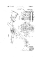
- Figure 1 is a side elevation of a portion of a steam shovel equipped with a trip mechanism constructed in accordance with the present. invention.
- Figure 2 isa view on a larger scale of a portion of the trip mechanism of Figure 1.
- Figure 3 is a sectional view taken substantially on the line 3 3 of Figure 2.
- Figure 4 is a View similar to Figure 2 of a portion of a. trip mechanism of somewhat different form. 70
- Figure 5 is a sectional view taken on the line 5-5 of Figure 4.
- the shovel selected for illustration includes a main platform 10, boom 11, ⁇ dip per 12 and dipper stick 13 constructed and 75 arranged in the usual manner.
- the dipper stick 15?C in this instance is bifurcated and straddles the boom, each of the legs 13 thereof resting upon and meshing with a pinion 14 mounted to rotateabout a shaft 15 Xed inx the boom.
- a saddle block structure 16 pivOta-lly mounted Ion each end of the shaft 15 retains the legs 13 in operative position and permits the dipper stick to swing about the axis of the shaft. Longitudinal shifting of the dipper stick is eiected by the usual boom engine 17, through the pinions 18 and gears 19, in the usual manner.
- the dipper door 2O is releasably retainedin closed position by the usual spring pressed latch21 connectedthrou h a cable 22 with a drum 23 fixed to a vsha 24 carried by the dipper stick.
- the present invention provides a new and ⁇ improved trip mechanism by which the latch may be released in any position of the dipper to effect opening of the di r door.
- the trip mechanism shown in ⁇ lgures 1, 2 and 3 rises a latch line 25 extendin parallel to t e ⁇ dipper ⁇ stick between one 0 10 the legs 13 thereof'and the corresponding saddle block structure 16.
- This line is secured at one end 26 a bracket 27 fixed to the rear end ofthe adJacent dipper stick leg and at 1ts other end 28 1s secured to an: up-
- the latch lever 29 is actuated by crimping the latch line 25.
- Mechanism yfor this purpose is mounted on the saddle block structure, so' as to rock therewith during swinging of the dipper stick, and in this instance/comprises a pair of spaced sheaves 30 journaled upon stub shafts 31 and 31 fixed in the -saddle block structure. These sheaves are arranged beneath the latch line and constitute a supporting guide therefor.
- a third sheave 32 is disposed above the latch line and contacts therewith intermediate the sheaves 30.
- This sheave is carried by a lever 33 rockably mounted upon the inner end of. shaft 31 and rigidly connected through a yoke 34'with an actuating lever 35 rockably mounted upon the outer end of shaft 31.
- the voke 34 serves toy partialiy counterbalance the weight of the levers 33'and 35 and the parts supported therebyv so thatthe sheave 32 normally rests lightly upon the latch line.
- this yoke also prevents undue movement of the sheave 32 away from the' 'latch line during swinging of the clipper stick and consequent rocking of the saddle block structure.
- Lever 35 is actuated preferably from the,
- this cable passes between a pair' of guide sheaves 38 by which it is directed 'substantially across the pivotal axis of the saddle block structure.
- y Sheaves 38 are journaled in a bracket 39constituting an integral part of a collar 4() fixed to the, end of shaft 15.
- the other end of cable 36 is connected f with any appropriate actuating; means.
- Figure 1 it is shown connected, as at 41, with one arm 42 of a bell crank, mounted on a fixed pivot 43 carried bythe main platform 10.
- the other arm- 44 of this bell crank is connected through a link 45 with an appropriate foot lever 46munted upon the platform and yieldabl retained in the normal inactive position s' own by any appropriate means,'such as a 'spring 47.
- a dipper trip mechanism is rovided in which the operating cables are ree from slack in all positions of the dipper. Since the latch line 25 is free to move lengthwise with the dipper stick it Since it is limited in its downward movement by the saddle block compensates completely for all longitudinal 'shifting thereof and since that portion of the cable 36 above the sheaves 38 is free to swing with ⁇ the saddle block structure about all swinging' movements of the clipper stick.
- the clipper door may be released by the operator in any position of the dipper by merely depressing the foot lever 46.
- This action of the foot lever rocks thebell crank arms 42 and 44 in a clockwise direction (Fig. 1), thereby exerting an effective pull on the cable 36, by which the lever 35, and consequently lever 33, -is swung downwardly and the sheave 32 pressed against 'the latch line 25 to crimp thesame between the sheaves 30.
- This crimping of the latch line causes latch lever 29 to swing to the left so that the drum 23, through the cable 22, withdraws the latch 21 into released posit-ion.
- the trip mechanism shown in Figures 4 and 5 is silnilar in many respects to that just described.
- the latch line 25 isl connected at its opposite ends with the
- a floating'sheave 52 is arranged between these pairs of sheaves, beneath the latch line and supported by the end 37 of an operating cable 36.
- This cable passes from the sheave 52 over a sheave 53, journaled between fixed brackets 54 carried by 'the saddle block structure, .and thence downwardly beneath a compensating sheave 55to an ap ropriate actuating means upon the main pl tform of the machine.
- Sheave 55 is journaled in a fixed bracket 56 fixed to the saddle block structure. Sheave 55 is so disposed with respect to the axis of shaft 15 as to fully compensate for any foreshortening effect that might otherwise be produced on the cable G by swinging of the saddle b'lock strucure.
- this form of -trip mechanism will also readily conform ⁇ to all movements' of the dipper stick, and that no slack occurs in either the o erating cable 36 or the .latch line 25 thereol during such movement.
- the flipper door latch mechanism may be released 1n any position of the di per by pulling the cable 36.
- a pull on t e cable 36 forces the sheave 52 upwardly against the latch line 25 and edects a crim ing thereof between the upper gui e sheaves 48 and 49.
- a power shovel having a dipper and dipper stick mounted @for swinging and shifting movements the combination of dipper door latch mechanism, a latch operating. line arranged to automatically compensate. for all shifting movements of the dipper stick, and latch line operating mechanism arranged to compensate for all swinging Inovements of the dipper stick.
- a )ower shovel having a dipper and dipper stlck mounted for swinging and shifting movements the combination of dipper door latch mechanism, a latch operating line connected with said dipper stick and extending parallel to the direction of shift.
- v 7 In a ower shovel having a dipper and dipiper stlck mounted y for swinging and shi per door latch mechanism, a latch operatin line extending substantially parallel to sai dipper stick in all positions thereof, and means for operating said line to release said latch mechanism comprising cable operated sheaves and a cable having' a substantially uniform degree of tautness in all positions of said dipper stick.
- a power shovel having a working platform and a dipper and dipper stick supported thereon for swinging and shifting movements
- dipper door latchimechanism a latch o erating line eX- tcnding substantially para lel to said dipper stick in all positions'thereof
- means including cable operated sheaves and a cable leading from said platform for operating said line to release said latch mechanism, means associated with said cable for maintaining the same in a taut condition during swinging movements otl said dipper stick, and means lon said platform for operating said cable.
- a power shovel having a dipper and dipper stick mounted for swinging and shifting movements, the combination of dipper latch mechanism, line crimplin mechanism, a latch leverpivoted on t e andle, and a latch operating line extendin from said lever, parallel to said dipper stlck and operatively associated with said crimping mechanism in the'various ipositions assumed by said dipper stick, said parallelism being attained by extending the latch levleriupwardly, rather than downwardly from its fulcrum.
Landscapes
- Engineering & Computer Science (AREA)
- Mechanical Engineering (AREA)
- Mining & Mineral Resources (AREA)
- Civil Engineering (AREA)
- General Engineering & Computer Science (AREA)
- Structural Engineering (AREA)
- Earth Drilling (AREA)
Description
Feb. 23 1926. 1,574,492
w. LEHMAN ET AL DIPPER TRIP Filed Sept. 4, 41925 2 Sheets-Sheet l Feb. 23 1926.
W. LEHMAN ET AL DIFFER TRIP Filed Sept. 4, 1923 2 Sheets-Sheet 2 A TTORNEY.
Patented Feb. 23, 1926.v
,UNITED STATESv PATENT OFFICE.
WERNER LEHIAN, FRED J. BREWER, AND ROGER SHERMAN'HOAR, OF SOUTH HIL- WAUKEE, AND BENJAMIN F. JOHNSTON AND MITCHELL L. FYKSE, OF IM[|4WA'U' m, WISCONSIN, A SSIGNORS TO BUCYRUS COMPANY, F SOUTH MILWAUKEE, WISCONSIN, A CORPORATION OF WISCONSIN.
DIPPER TRIP.
Application filed September 4, 1923.` Serial` No. 660,903.
To all wlwm v'it may concern.'
Be it known that we, WERNER LEHMAN. FRED J. BREWER, yand ROGER SHERMAN HOAR, residing at South Milwaukee, and
I `BENJAMIN F. JOHNSTON and MITCHELL L. Frxsr., residing at Milwaukee, all in the count of Milwaukee and State of Visconsin, cltizens of the United States, have invented a certain new and useful Improvel0 ment in Dipper Trips, of which the following is a ful clear, concise. and exact description, reference being had to the accompanying drawings, forming a part of this specification.
This invention relates to dipper trip mechanisms for power shovels.
`Considerable difficulty has been experienced in devising a dipper trip mechanism that will function satisfactorlly and uniformly under all conditions of operation and in the various positions assumed by the dipper during normal working. This is due, at least in part, to the various degrees of slack ordinarily occurring in the latch line or other operating cable as the dipper is moved from point to point throughout its operating range. Attem ts heretofore made to overcome this diflicu ty have met with partial success. Devices for automatically l 30. takin upthe slack as it occurs have been intro uced. These have their objections. Some are limited in their application to machines of a particular mechanical design.`
Others lead to mechanical complications. One object of the present invention is the provision. of a.l dpper trip mechanism which will so conform to various positions of the ldipper as to avoid the occurrence of any slack therein. i
Another object is the provision. of a novel arrangement of latch line which will vfully com ensate for al1 lengthwise shifting of the ipper stick and thereby avoid the necessit for any slack take-up mechanism.
Another object is the provision of a novel arrangement of trip operating vcable which will fully compensate for all swinging movements of the dipper stick.
Another object is the provision of a novel system of dippertrip cables which will fully compensate for both swinging and shifting movements of the dipper stick and so permit mechanical operation from the main platform of the machine without requiring slack take-up mechanism.
Other objects and advantages will appear from the following-description of two embodiments of this invention.
ln the drawings:
Figure 1, is a side elevation of a portion of a steam shovel equipped with a trip mechanism constructed in accordance with the present. invention.
Figure 2 isa view on a larger scale of a portion of the trip mechanism of Figure 1.
Figure 3 is a sectional view taken substantially on the line 3 3 of Figure 2.
Figure 4 is a View similar to Figure 2 of a portion of a. trip mechanism of somewhat different form. 70
Figure 5 is a sectional view taken on the line 5-5 of Figure 4. v
The shovel selected for illustration includes a main platform 10, boom 11,`dip per 12 and dipper stick 13 constructed and 75 arranged in the usual manner. The dipper stick 15?C in this instance is bifurcated and straddles the boom, each of the legs 13 thereof resting upon and meshing with a pinion 14 mounted to rotateabout a shaft 15 Xed inx the boom. A saddle block structure 16 pivOta-lly mounted Ion each end of the shaft 15 retains the legs 13 in operative position and permits the dipper stick to swing about the axis of the shaft. Longitudinal shifting of the dipper stick is eiected by the usual boom engine 17, through the pinions 18 and gears 19, in the usual manner. The dipper door 2O is releasably retainedin closed position by the usual spring pressed latch21 connectedthrou h a cable 22 with a drum 23 fixed to a vsha 24 carried by the dipper stick.
The present invention provides a new and` improved trip mechanism by which the latch may be released in any position of the dipper to effect opening of the di r door. The trip mechanism shown in `lgures 1, 2 and 3 com rises a latch line 25 extendin parallel to t e `dipper `stick between one 0 10 the legs 13 thereof'and the corresponding saddle block structure 16. This line is secured at one end 26 a bracket 27 fixed to the rear end ofthe adJacent dipper stick leg and at 1ts other end 28 1s secured to an: up-
right latch lever 29 fixed to theshaft 24.
'l` he arrangement'is such that the condition oi the line and its position relative to Athe dipper stick is undisturbed by swinging and lengthwise shiftim;r of the dipper stick.
The latch lever 29 is actuated by crimping the latch line 25. Mechanism yfor this purpose is mounted on the saddle block structure, so' as to rock therewith during swinging of the dipper stick, and in this instance/comprises a pair of spaced sheaves 30 journaled upon stub shafts 31 and 31 fixed in the -saddle block structure. These sheaves are arranged beneath the latch line and constitute a supporting guide therefor. A third sheave 32 is disposed above the latch line and contacts therewith intermediate the sheaves 30. This sheave is carried by a lever 33 rockably mounted upon the inner end of. shaft 31 and rigidly connected through a yoke 34'with an actuating lever 35 rockably mounted upon the outer end of shaft 31. The voke 34 serves toy partialiy counterbalance the weight of the levers 33'and 35 and the parts supported therebyv so thatthe sheave 32 normally rests lightly upon the latch line.
structure, this yoke also prevents undue movement of the sheave 32 away from the' 'latch line during swinging of the clipper stick and consequent rocking of the saddle block structure.
instance, this cable passes between a pair' of guide sheaves 38 by which it is directed 'substantially across the pivotal axis of the saddle block structure.y Sheaves 38 are journaled in a bracket 39constituting an integral part of a collar 4() fixed to the, end of shaft 15. The other end of cable 36 is connected f with any appropriate actuating; means. In
Figure 1 it is shown connected, as at 41, with one arm 42 of a bell crank, mounted on a fixed pivot 43 carried bythe main platform 10. The other arm- 44 of this bell crank is connected through a link 45 with an appropriate foot lever 46munted upon the platform and yieldabl retained in the normal inactive position s' own by any appropriate means,'such as a 'spring 47.
This it will be noted that a dipper trip mechanism is rovided in which the operating cables are ree from slack in all positions of the dipper. Since the latch line 25 is free to move lengthwise with the dipper stick it Since it is limited in its downward movement by the saddle block compensates completely for all longitudinal 'shifting thereof and since that portion of the cable 36 above the sheaves 38 is free to swing with `the saddle block structure about all swinging' movements of the clipper stick.
The clipper door may be released by the operator in any position of the dipper by merely depressing the foot lever 46. This action of the foot lever rocks thebell crank arms 42 and 44 in a clockwise direction (Fig. 1), thereby exerting an effective pull on the cable 36, by which the lever 35, and consequently lever 33, -is swung downwardly and the sheave 32 pressed against 'the latch line 25 to crimp thesame between the sheaves 30. This crimping of the latch line causes latch lever 29 to swing to the left so that the drum 23, through the cable 22, withdraws the latch 21 into released posit-ion.
The trip mechanism shown in Figures 4 and 5 is silnilar in many respects to that just described. The latch line 25 isl connected at its opposite ends with the |rear end of the dipper stick and with an upright latch lever, respectively, as hereinabove described, and extends parallel with the dipper stick. In this instance, however, it passes outside of the saddle block structure 16 between two pairs of guide sheaves 48 and 49 mounted within brackets 50 and 51 fixed to the saddle block structure outside thereof. A floating'sheave 52 is arranged between these pairs of sheaves, beneath the latch line and supported by the end 37 of an operating cable 36. This cable passes from the sheave 52 over a sheave 53, journaled between fixed brackets 54 carried by 'the saddle block structure, .and thence downwardly beneath a compensating sheave 55to an ap ropriate actuating means upon the main pl tform of the machine. Sheave 55 is journaled in a fixed bracket 56 fixed to the saddle block structure. Sheave 55 is so disposed with respect to the axis of shaft 15 as to fully compensate for any foreshortening effect that might otherwise be produced on the cable G by swinging of the saddle b'lock strucure.
It wlll thus be seen that this form of -trip mechanism will also readily conform `to all movements' of the dipper stick, and that no slack occurs in either the o erating cable 36 or the .latch line 25 thereol during such movement. As in the mechanism first described, the flipper door latch mechanism may be released 1n any position of the di per by pulling the cable 36. A pull on t e cable 36 forces the sheave 52 upwardly against the latch line 25 and edects a crim ing thereof between the upper gui e sheaves 48 and 49. i
Various changes may be made in the embodiments of the invention hereinabove described, without departing from or sacrificing any' of the advantages of the invention as defined in the appended claims.
IVe. claim:
1. In a power shovel having a dipper and dipper stick mounted @for swinging and shifting movements the combination of dipper door latch mechanism, a latch operating. line arranged to automatically compensate. for all shifting movements of the dipper stick, and latch line operating mechanism arranged to compensate for all swinging Inovements of the dipper stick.
9. In a )ower shovel having a dipper and dipper stlck mounted for swinging and shifting movements the combination of dipper door latch mechanism, a latch operating line connected with said dipper stick and extending parallel to the direction of shift.
ing movement thereof, and means operable upon said line to release said latch mechanism in any position of said dipper stick.
3. In a power shovel having a dipper and dip er stick mounted for swinging and shi ting movements the combination of dipper latch mechanism, line crimping mechanism, and a latch operating line extending parallel to said dipper stick and operatively associated with said crimping mechanism in the various positions assumed by said dipper stick. i
4. In a power shovel the combination of a dipper and dipper stick, a pivoted guide in which said dipper stick may reciprocate longitudinally, dipper door latchmechanism, a latbh operating line, means carried by said guide for operating said line, and a cablel substantiall intersecting the pivotal axis of said gui e for actuating said line operating means.
5. In a ower shovel the combination of a dipper an dipper stick, a pivoted guide'in which said dipper stick may reciprocate longitudinally, dipper door latch mechanism, a
atch operating line, means carried by said guide for o rating said line, a cable for actuating said means, and a guide sheave for saidi cable adjacent the pivotal axis of said gui e.
6. In a power shovel the combination of a dipper and dipper stick, dipper door latch mechanism, an upright latch operating lever, a latch o erating line connected at one end with sai lever and at the other end with said dipper stick, l-ine crimping mechanism operatively Vassociated ywith said line, and
means for actuating said' crimping mechanism. v 7 In a ower shovel having a dipper and dipiper stlck mounted y for swinging and shi per door latch mechanism, a latch operatin line extending substantially parallel to sai dipper stick in all positions thereof, and means for operating said line to release said latch mechanism comprising cable operated sheaves and a cable having' a substantially uniform degree of tautness in all positions of said dipper stick.
8. In a power shovel having a working platform and a dipper and dipper stick supported thereon for swinging and shifting movements, the combination of dipper door latchimechanism, a latch o erating line eX- tcnding substantially para lel to said dipper stick in all positions'thereof, means including cable operated sheaves and a cable leading from said platform for operating said line to release said latch mechanism, means associated with said cable for maintaining the same in a taut condition during swinging movements otl said dipper stick, and means lon said platform for operating said cable.
9. In a power shovel having a dipper and dipper st1ck mounted for swingmg and shifting movements, the combination ofdipper door latch mechanism and a two part latch operating line so dis osed that one part compensatesfully for al shifting movements ofthe dipper stick and is free from disturbance by swinging movements thereof, and the other part compensates fully for all swinging movements of the dipper stick and is free from disturbance by shifting movements thereof.l
10. In a power shovel, having a dipper and dipper stick mounted for swinging and shifting movements, the combination of dipper latch mechanism, line crimplin mechanism, a latch leverpivoted on t e andle, and a latch operating line extendin from said lever, parallel to said dipper stlck and operatively associated with said crimping mechanism in the'various ipositions assumed by said dipper stick, said parallelism being attained by extending the latch levleriupwardly, rather than downwardly from its fulcrum. l
11. In a power shovel, havin a dipper and dipper stick mounted for swmging and shifting movements, the combination of dipper latch mechanism, line crimping mechanism, a latch lever pivoted on the handle,
and a latch .operating line extending from saidlever to attaching means adjacent the rear end of the handle, parallel to said dipper stick and operatively associated with said crimping mechanism in the various positions assumed by said dipper stick, said parallelism being attained by extendin the latch lever upwardly, rather than ownwardly from its fulcrum.
/In witness whereof, we hereunto subscribe our names July, 1923. ing movements, the combination of dip- WERNER LEHMAN.
FRED J. BREWER.
ROGER SHERMAN HOR. BENJAMIN F. JOHNSTON.` MITCHELL L. FYKSE.
Priority Applications (1)
| Application Number | Priority Date | Filing Date | Title |
|---|---|---|---|
| US660903A US1574492A (en) | 1923-09-04 | 1923-09-04 | Dipper trip |
Applications Claiming Priority (1)
| Application Number | Priority Date | Filing Date | Title |
|---|---|---|---|
| US660903A US1574492A (en) | 1923-09-04 | 1923-09-04 | Dipper trip |
Publications (1)
| Publication Number | Publication Date |
|---|---|
| US1574492A true US1574492A (en) | 1926-02-23 |
Family
ID=24651412
Family Applications (1)
| Application Number | Title | Priority Date | Filing Date |
|---|---|---|---|
| US660903A Expired - Lifetime US1574492A (en) | 1923-09-04 | 1923-09-04 | Dipper trip |
Country Status (1)
| Country | Link |
|---|---|
| US (1) | US1574492A (en) |
Cited By (2)
| Publication number | Priority date | Publication date | Assignee | Title |
|---|---|---|---|---|
| US2435740A (en) * | 1946-03-28 | 1948-02-10 | James H Edwards | Trip mechanism for power shovels |
| US12312765B2 (en) | 2013-09-27 | 2025-05-27 | Joy Global Surface Mining Inc | Dipper door and dipper door trip assembly |
-
1923
- 1923-09-04 US US660903A patent/US1574492A/en not_active Expired - Lifetime
Cited By (2)
| Publication number | Priority date | Publication date | Assignee | Title |
|---|---|---|---|---|
| US2435740A (en) * | 1946-03-28 | 1948-02-10 | James H Edwards | Trip mechanism for power shovels |
| US12312765B2 (en) | 2013-09-27 | 2025-05-27 | Joy Global Surface Mining Inc | Dipper door and dipper door trip assembly |
Similar Documents
| Publication | Publication Date | Title |
|---|---|---|
| US2345620A (en) | Tractor propelled implement | |
| US1574492A (en) | Dipper trip | |
| US2719641A (en) | Earth moving apparatus or the like | |
| US2531993A (en) | Tractor operated loading device | |
| US2139255A (en) | Excavating machine | |
| US1769991A (en) | Excavating apparatus | |
| US1711896A (en) | Control mechanism for power shovels, hoists, cranes, and the like | |
| US1783056A (en) | Instroke shovel crane | |
| US2164126A (en) | Electrically operated dipper trip | |
| US2423193A (en) | Overhead shovel | |
| US1822338A (en) | Excavator | |
| US1893564A (en) | Accelerator attachment for excavating machines | |
| US1470332A (en) | Power trip | |
| US3517846A (en) | High lift bucket | |
| US1813110A (en) | Excavator | |
| US1598802A (en) | Fair lead | |
| US1443353A (en) | Rope thrusting shovel | |
| US1891427A (en) | Scraper and apron | |
| US2304524A (en) | Control for shovels | |
| FR2340466A1 (en) | Bearing shaft for mechanical digger bucket arms - carries levers spaced by retractable bosses with flange on auxiliary shaft | |
| US1486834A (en) | Saddle-block structure for power shovels | |
| US1785492A (en) | Back digger | |
| US1907442A (en) | Hydraulic power shovel | |
| US1439216A (en) | Power shovel | |
| US1731673A (en) | Dipper-dumping control for shovels |