US1574484A - Multiplex signaling system - Google Patents
Multiplex signaling system Download PDFInfo
- Publication number
- US1574484A US1574484A US488297A US48829721A US1574484A US 1574484 A US1574484 A US 1574484A US 488297 A US488297 A US 488297A US 48829721 A US48829721 A US 48829721A US 1574484 A US1574484 A US 1574484A
- Authority
- US
- United States
- Prior art keywords
- carrier
- filter
- telephone
- frequencies
- telegraph
- Prior art date
- Legal status (The legal status is an assumption and is not a legal conclusion. Google has not performed a legal analysis and makes no representation as to the accuracy of the status listed.)
- Expired - Lifetime
Links
- 230000011664 signaling Effects 0.000 title description 14
- 230000005540 biological transmission Effects 0.000 description 124
- 239000004020 conductor Substances 0.000 description 32
- 239000002131 composite material Substances 0.000 description 13
- 230000008878 coupling Effects 0.000 description 3
- 238000010168 coupling process Methods 0.000 description 3
- 238000005859 coupling reaction Methods 0.000 description 3
- 230000008054 signal transmission Effects 0.000 description 3
- KHOITXIGCFIULA-UHFFFAOYSA-N Alophen Chemical compound C1=CC(OC(=O)C)=CC=C1C(C=1N=CC=CC=1)C1=CC=C(OC(C)=O)C=C1 KHOITXIGCFIULA-UHFFFAOYSA-N 0.000 description 2
- 230000004044 response Effects 0.000 description 2
- 241000947840 Alteromonadales Species 0.000 description 1
- 241000272470 Circus Species 0.000 description 1
- 241001233242 Lontra Species 0.000 description 1
- 230000004075 alteration Effects 0.000 description 1
- 230000008901 benefit Effects 0.000 description 1
- 239000000969 carrier Substances 0.000 description 1
- 230000008859 change Effects 0.000 description 1
- 238000010276 construction Methods 0.000 description 1
- 238000001914 filtration Methods 0.000 description 1
- 230000009467 reduction Effects 0.000 description 1
- 230000001629 suppression Effects 0.000 description 1
Images

Classifications
-
- H—ELECTRICITY
- H04—ELECTRIC COMMUNICATION TECHNIQUE
- H04J—MULTIPLEX COMMUNICATION
- H04J1/00—Frequency-division multiplex systems
Definitions
- This invention relates to a multiplex sys-.
- the invention provides a system of this general character which is flexible in use 1n that it may be readily altered to suit different kinds and conditions of transmission;
- multiplex signal transmission is accomplished over a common transmission medium or line.
- Transmission of several kinds of signals may be carried on at the same time and in both directions through the system, and these different kinds of signals and the different directions of transmission are distinguished by the different frequencies that are employed.
- Wave filters and tuned circuits are used to separate the various distinctive frequencies one from another, and a minimum number of such cirvcuits is used to separate efficiently the several rier transmissions.
- transmissions Normally, transmissions of an ordinary telephone line such as ordinar telephone, Morse telegraph, and other signa ing currents within or below the ordmary telephone range are se arated from the carhe carrier transmissions comprising telephony and telegraphy are separated from each other. In some cases certain distinctive frequencies used for carrier telephony are grouped with the carrier telegraph distinctive frequencies for selective purposes. Switching means permit of increasing the number of'carrier telephone transmissions if for any reason the carrier.
- an ordinary telephone line such as ordinar telephone, Morse telegraph, and other signa ing currents within or below the ordmary telephone range are se arated from the carhe carrier transmissions comprising telephony and telegraphy are separated from each other.
- certain distinctive frequencies used for carrier telephony are grouped with the carrier telegraph distinctive frequencies for selective purposes. Switching means permit of increasing the number of'carrier telephone transmissions if for any reason the carrier.
- telegraph channels are in operation at the time.
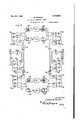
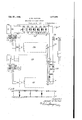
- Figs. 1, 2, 3-, 4 and 5, when arranged according to Fi 9, show one embodiment of the invention 1n which Fig. 1 shows the carrier telegraph and carrier telephone apparatusat'one terminal station; Fig. 2, the selective circuits at the same station; Fig. 3, the apparatus and selective circuits at a midline repeater station; Fig. 4, the selective circuits at the. other station; and Fi 5, the
- Fig. 6 also shows the apparatus and selective circuits at a mid-line repeater station which differs slightly from that ofFig. 3, and may be substituted therefor to constitute a modified system;
- Fig. 7 shows a modified arrangement of terminal apparatus and selective circuits;
- Fig. 8 shows a filter arrangement which ma be substituted for one of the filters of Fig.
- Figs. 1, 2, 3, 4: and 5 arranged according to. Fig. 9, the terminal station of Figs. 1 and 2, hereinafter called the west station, is connected to the terminal station shown in Figs. 4. and 5, hereinafter called the east station, by. means of a common transmission line -ML.
- a common transmission line -ML a common transmission line
- Filter 26 is adapted to pass with substantially negligible attenuation all currents having frequencies of 3,333 cycles and above, and to greatly attenuate currents having a frequency less than 3333 cycles
- filter 27 is adapted to pass with substantially negligible attenuation all currents having frequencies of 3000 cycles or less and to highly attenuate all currents having frequencies above 3000.
- Such an arrangement of filters is shown in Fig.
- filters 28 and 29 are provided.
- Filter 28 is a low pass filter adapted to pass with substantially negligible attenuation, frequencies of 9030 cycles and under, and to highly attenuate all frequencies above that value.
- Filter 29 is a high pass filter adapted to pass with substantially negligible attenuation, frequenciesof 10,000 cycles and above, and to highly attenuate all. frequencies below that value.
- filters 30 and 31 are provided to separate the frequencies used for transmission from the west station from those used for reception thereat.
- Filter 30 is a low pass filter adapted topass with substantially negligible attenuation, frequencies of 5500 cycles and lower and to highly attenuate all frequencies above 5500 cycles.
- Filter 31 is a high pass filter adapted to pass the fre' quency of 6500 cycles, and all frequencies above that value, and to highly attenuate all frequencies below 6500 cycles. These filters will hereinafter be called carrier telegraph grouping filters.
- Filters S to S inclusive are provided to separate the frequencies used for carrier telegraph transmitting at the West station. It is not necessary to use filters for this purpose, and in the preferred form tuned circuits are used instead of wave filters to separate the frequencies used for carrier telegraph reception. At the west station selec tive circuits R to R inclusive are employed. The carrier telegraph terminal apparatus.
- the sending circuit comprising the oscillater 0, amplifier A, and sending relay 8, is
- the sending selective circuit is connected to the sending selective circuit S by conductors 5.
- the receiving circuit comprising amplifier A detector TD and receiving relay 6, is connected to the receiving selective circuit R by conductors 7.
- the sending relay 8 and receiving relay 6 are associated with an ordinary Mors'e telegraph line 9 and an artificial line AL in the well known manner for duplex operation.
- Similar carrier telegraph apparatus may be connected to each of the other sending selective circuits S to S inclusive, and receiving selective circuits R to R inclusive to provide additionalcarrier telegraph channels.
- Selective circuits S and B may be used to provide an additional carrier telegraph duplex channel under certain circumstances which will be explained hereinafter.
- Filter 32 is provided to separate the frequencies used for carrier telephone reception at the west station as a group from the frequencies used for transmission from the same station.
- This filter 32 is a low pass filter adapted to pass with substantially negligible attenuation, a frequency of 18,666 cycles, and all frequencies below that value and to highly attenuate all frequencies above that value.
- This filter will hereinafter be called the carrier telephone grouping filter.
- the frequencies used by the several channels for carrier telephone transmission from .the west station are separated from one another by band filters 33 to 36 inclusive, and the frequencies used for reception for the several channels at the same station are separated by band filters 37 to 40 inclusive.
- Each of these filters is adapted to pass with substantially negligible attenuation a band of frequencies characteristic of the telephone transmission of that channel and to highly attenuate all frequencies outside of that band.
- Band filters 36 and 40 are shown by dotted.lines, since they are not used under certain circumstances hereinafter to be described.
- the carrier telephone apparatus is similar to that of Fig. 49 of the Golpitts and Blackwell aper, supra.
- An ordinary telephone line is associated with a carrier telephone transmitting circuit TC, and the carrier telephone receiving circuit RC by means of a conjugate transformer or hybrid coil 10 with the low frequency balancing net N.
- Transmitting circuit TC comprises a modulatorM and transmitting amplifier TA and is connected to the transmitting band filter 33 by conductors 11.
- the receiving circuit RC comprising a detector 1), a detector amplifier DA and a low pass filter LPF, is connected to the receiving band filter 37 by means of conductors 12.
- each channel is supplied with a frequency which is a harmonic of a base frequency which in this case is 3,333 cycles.
- This base frequency together with the harmonics thereof is supplied by the harmonic vided.
- the modulator M is supplied with carrier current of one carrier frequency bythe sending harmonic amplifier SHA while the demodulator D is supplied with current of one carrier frequency by the receiving harmonic amplifier RHA. It is understood that at some suitable point in the amplifier circuits SHA and RHA a selective circuit for one particular carrier frequency is em- )loyed, as for example between the ampliner element and the branch HCW or between the amplifier element and the modulater or detector.
- twin jacks J may be connected either to the harmonic generator through twin jacks J 2 or to the harmonic regenerato-r HRG through twin jacks J
- twin jacks J 4 to J 9 inclusive, and twin plugs P to P inclusive and interconnecting two-conductor cords to 37 in clusive provision is made to connect either the carrier telegraph terminal alone, or the carrier telephone terminal alone, or both the carrier telegraph and carrier telephone terminals together to the common carrier circuit CO
- twin jacks J 4 to J 9 inclusive, and twin plugs P to P inclusive and interconnecting two-conductor cords to 37 in clusive provision is made to connect either the carrier telegraph terminal alone, or the carrier telephone terminal alone, or both the carrier telegraph and carrier telephone terminals together to the common carrier circuit CO
- The-various connections will be described more in detail hereinafter.
- line L and the common carrier circuit C0 are connected to the common line ML by a high-frequency composite set to the main line ML at the left, comprising the high pass filter 51- and the low' pass filter 52.
- Filters 51 and 52 are s mllar respectively to filters 26 and 27.
- Carrler grouping filters are also provided and comprise a low pass filter 53 and a high pass filter 54.
- Filters 53 3.116154 are similai respectively to filters 28 and 29 of Fi 2.
- Carrier telegraph transmissions east are separated from transmissions west by low pass filters 55 and 56 and high pass filters 57 and 58 respectively.
- Filters 55 and 56 are adapted to pass the same range of frequencies as filter 30 of Fig.2, and filters 57 and 58, the same range of frequencies as filter 31 of Fig. 2.
- the carrier-telephone repeater elements RE and RW are provided for repeating transmissions east and transmissions west respectively. These elements may be similar to repeater elements TRE and TRW' of the carrier telegraph repeater.
- High pass filters 59 and 60 and low pass filters 61 and 62 I are provided to separate the carrier telephone transmissions east from the transmissions west.
- Filters 61 and 62 are adapted to pass the same range of frequencies as filter 32 of Fig. 2.
- Filters 59 and 60 are adapted to pass all frequencies from 21333 cycles upwards inclusive, and therefore are adapted to pass all of the frequencies which are passed by filters 33 to 36 inclusive of Fig. 2.
- the carrier grouping filters 63 and .64 separate the carrier telegraph transmissions from the carrier telephone transmissions on the right of Fig. 3.
- Filters 63 and 64 are similar to and adapted to pass the same range of frequencies as filters 28 and 29 respectively of- Fig. 2.
- a high frequency composite set compris-, ing high pass filter 65 and low pass filter 66 is provided to connect the common carrier circuit CC and the ordinary telephone line .L to the common line ML.
- High pass filter 65 and low pass filter 66 are similar respectively to high pass filter 26 and low pass filter 27 of Fig. 2.
- Twin jacks J to J inclusive on the left, and twin jacks J to .J inclusive on the right, and twin plugs P to P on the left, and twinplugs P to P on the right, together with twin conductors 67 to 69 inclusive on the left, and-twin conductors 70 to 72 on the right, provide means for connecting.
- the east station is quite similar to the west station.
- the high frequency composite set comprising the high pass filter 76 and the low pass filter 77 connects the common carrier circuit CC and the ordinary telephone line L to the common line ML.
- Filters 76 and 77 correspond respectively to filters 26 and27 of Fig. 2.
- Low pass filter 78 and high pass filter 79 are the carrier grouping filters of the east statiomand correspond'respectively to filters 28 and 29 of the west station.
- filters 32 and 82 are each in the receiving branch of their respective stations.
- One important purpose served by these carrier telephone'grouping filters is the reduction of any tendency for cross talk between the different channels due for example to energy from any of the transmitting circuits 3336 finding its way through any of the receiving filters 37-40.
- These receiving filters have their terminal sections all connected to the common ter-' minal circuit, to the other branch of which the transmitting channels are connected.
- the currents impressed on this terminal circuit from the transmitting channels are of relatively high amplitude and any filters which are to be employed to keep these currents out of the receiving channels must offer very high attenuation tothe currents of these frequencies.
- the channel filters 3740 alone were relied on for this purpose theymust each be made to have very high attenuation to foreign frequencies and this would incur considerable expense. However by using a grouping filter 32 of moderately high attenuation for the transmitting frequencies, the channel filters 3740 need have only moderatelyfhighattenuation for foreign frequencies. ⁇ They will then effectively separate the received frequencies which are of relatively low am-,
- plitude, and the attenuation-which they otter to the transmitting frequencies together with the grouping filter 32 can still be very high without necessitating the costly construction required without the grouping filter.
- a corresponding filter is shown at 82
- Selective circuits ES to ES inclusive correspond to the sending selective circuits S to- S of the west station and cooperate with the receiver selective circuits R to R inclusive of that station.
- the receiving selective circuits EH to ER inclusive of the east station correspond to the receiving selective circuits R to R inclusive of the west station and cooperate with the sending selective circuits S to S inclusive of that station.
- the carrier telegraph terminal apparatus of the east station com rises the sending relay 101 associated wit the os cillator O, the amplifier A connected to the tuned circuit ES by conductors 83, and the receiving relay 102, detector TD receiving amplifier A connected to the receiving selective circuit ER by conductors 84.
- An ordinary telegraph line 103 and an artificial line AL are associated with the sending relay 101, and receiving relay 102 by the well known duplex telegraph circuit.
- Band filters 85 to 88 inclusive are connected in the transmitting circuits of the several telephone channels and correspond to band filters 33 to 36 inclusive of Fig. 2, and cooperate with band filters 37 to 40 inelusive of Fig. 2.
- Receiving band filters 89 to 92 inclusive of theeast station 001 respond to receiving band filters 37 to 40 inclusive of the-west station.
- the ordinary telephone line is connected to the transmitting circuit TOE and the receiving circuit RCE bythe hybrid coil 104 and its balancing network N.
- the transmitting circuit TCE and the receiving circuit ROE are similar to the transmitting circuit TC and receiving circuit RC respectively of the west station and comprise respectively a modulator M and an amplifier TA connected to filter 85 by conductors 93 and demodulator D, a demodulator amplifier DA, and a low pass filter LPF connected to filter 89 by conductors 94.
- a sending harmonic amplifier SHA and a receiving harmonic amplifier RHA are connected respectively with the modulator M and the detector D.
- the harmonic generator HG, the harmonic regenerator EHRG, the transmitting base frequency amplifier ETBA, and a receiving base frequency amplifier EBA corresponding to the harmonic generator HG,the harmonic regenerator HRG, the transmitting base frequency amplifier WTBA, and a receiving base requency amplifier VVBA on the west station are provided at the east statio
- the harmonic generator HG, or the harmonic regenerator EHRG may be contraced.
- the transmission circuits will be completed by inserting the twin plugs P to P inclusive, respectively, into twin jacks J to J inclusive.
- Morse telegraph and ordinary telephone and telephone signaling transmissions, the essential frequencies of which are no greater than 3000 cycles follow a path which may be traced y from low frequency line L of Fig. 2, through low pass filter 27, common line ML of Fig. 2, common line ML of Fig.
- Carrier telegraph transmission from the line 9 at the west station to 'line103 at the east station will now/be traced.
- Such a transmission in the form of dots and dashes with corresponding impulses of current in line 9 will operate sending relay 8 in a well known manner.
- the oscillator O is normally generating current of 3810 cycles. This current is normally short-circuited through condensers 14 and the contact of sending relay 8.
- sending relay 8 in response to the dot and dash impulses removes this short-circuit and allows impulses of carrier current to pass to the amplifier A from which it flows through conductor-s 5, transmitting sending selective circuit S transformer 41, low pass filter 30, twin jacks J twin plugs P conductors of cord .35, twin plugs P, twin jacks J", low pass'filter 28, twin'jacks J, twin plugs P, conductors of cord 36, twin plugs P, twin jacks J, common carrier circuit CC, high pass filter 26,'common line ML of Fig.2 to the common line LIL at the left side of Fig.
- twin jacks J low pass filter 63 twin jacks J twin plugs P conductors of cord 71, twin plugs 1", twin jacks J common carrier circuit CC, high pass filter 65, common line ML at the right side of Fig. 3 to common line ML of Fig. 4, high pass filter 76, common carrier circuit CC, twin jacks J twin plugs P conductors of cord 95, twin plugs P, tw-in jacks J low pass filter 78, twin jacks J twin plugs P conductors of cord 96, twin plugs P twin jacks J low pass filter 80, transformer 98,
- Receiving relay 102 responds to impulses of current from the detector TD under control of the carrier current impulses to close its contact. The closing of the contact of receiving relay 102 sends impulses of current from source 106 to the telegraph line 103. Theseimpulses of current will operate telegraphic receiving apparatus in the well known manner,
- twin jacks J common carrier circuit CC? o high pass filter 51,.common line ML at left side of Fig. 3, common line ML of Fig. 2, high pass filter 26, common carrier circuit CC twin jacks J, twin plugs P cord 36, twin plugs P, twin jacks J low pass filter 28,- twin jacks J twin plugs P, cord 35, twin plugs P twin acks J high pass filter 31, transformer 4-2, receiving selectivecircuit R conductors 7 of Figs. 2 and 1, receiving amplifier A detector TD to receiving relay 6. The operation of receiving relay 6 in response to impulses of current received by detector TD, closes a circuit from a source 15 to the telegraph line 9 and operates telegraphic receiving apparatus in a well known manner.
- Typical carrier telephone transmissions will now be traced through a circuit.
- the base frequency for all the currents is generated in the harmonic generator HG of Fig. 1.
- Twinplugs P? are inserted in twin jacks J wh le twin plugs P are inserted in twin jacks J to complete a circuit for carrier current from the harmonic generator HG of Fig. 1 to the modulator M and detector D in the same figure.
- Base frequency and its harmonics are transmitted from the output of the harmonic generator HG through twin jacks J twin plugs P cord.13, twin plugs P twin jacks J 3 to the harmonic circuit HCVV. From this circuit, current of proper frequency is transmitted to the modulator M through the harmonic amplifier SHA in the manner shown in Fig. 4.9 of the Colpitts and Blackwell paper.
- carrier current for the demodulator D is received from the harmonic circuits HCW through the harmonic amplifier RHA.
- Thebase frequency from the harmonic generator HG, Fig. 1 is transmitted to the east station of Fig. 5 through the base a frequency amplifier WT BA, conductors 16 of Figs. 1 and 2, filter 33, line side of transformer 41, thence to the line side of transformer 98 of Fig. 4, through the same circuit tra ed for the carrier telegraph transmission from west to east, filter 100, conductors 108 of Figs. 1 and 5, base frequency amplifier EBA to the harmonic regenerator EHRG.
- a circuit for the output energy for the harmonic regenerator EHRG to the carrier terminal apparatus is completed by inserting twin plugs P into twin jacks 29, and twin plugs P into twinjacks. J forming a path through cord 105 to the common harmonic circuit HOE. From this circuit, current is supplied to the modulator M and the detector D through the sending harmonic amplifier SHA, and the receiving harmonic amplifier RHA, respectively.
- high pass filter 76 common carrier circuit CC
- twin jacks J twin plugs P cord 95, twin plugs P, twin jacks J high pass filter 79, twin jacks J twin plugs P cord 97, twin plugs P twin jacks J high pass filter 82, band filter 89, conductors 94: of Fig. 4 and Fig. 5 to detector D.
- modulated carrier and carrier current from the receiving harmonic amplifier RHA are demodulated and the resulting voice currents are transmitted from the output of the demodulator D through the demodulator amplifier DA and low pass filter LPF to the telephone line L.
- a telephone transmission from east to west from the line L of Fig. 5 to the line L of .Fig. 1 employs a carrier frequency of 10,000, and the'upper side band comprising frequencies of 10,000 to 12,000 is transmitted.
- the modulator M of Fig. 5 receives a high frequency wave of 10,000 cycles from the harmonic suppl circuit HCE, and through the amplifier S A and receives incoming voice currents from the line L through the circuit TCE.
- the resulting modulated wave passes through the amplifier TA and the circuit 93 to the filter 85 which passes the upper side band only.
- This upper side band passes throu h the terminals of jack J and jack J hlgh pass filter 79, jack J 25 and J high pass filter 76, east section of the mainline ML, high pass filter 65, jacks by connecting jack I.
- an object accomplished by the present system is a flexible arrangement of the connections whereby the circuits may readily be set to transmit current of speech fre uency, high frequency telegraph and high requency telephone as has been described.
- the system may be arranged to transmit either high frequency telegraph or high frequency telephone alone in addition to the normal or ordinary low frequency transmission.
- the number of available channels may, according to the invention, be increased by using for the high frequency telegraph, apparatus which is normally devoted to high frequency telephone transmission or vice versa as the casemay be.
- igh frequency telegraph transmission in the opposite direction through the channel connecting lines 103 and 9 reaches the terminals of jack J as previously described, and thence follows the path just now traced for transmission from west to east except that the filters 58 and 57 direct the transmission in view of its frequency through the west repeater TRWV, and upon reaching the terminals of jack J*, the west transmission is selectively passed by the filter 31 into the receiving side of the telegraph circuit.
- An ordinary -Morse telegraph line 9 with its associated balancing artificial line- AL, transmitting and receiving relays 8 and 6 and detector TD may be associated with the input of amplifier lVTBA and the output of an amplifier lVBA by means of switches SW and SW
- This telegraph equipment is similar to that shown at the top of Fig. 1 and associated with the input of amplifier A and'the output of amplifierA
- the switches SW and SW are in the position shown in the drawing so that the, Morse telegraph equipment is disconnected.
- the switches SW and SW may be thrown so as to connect the Morse telegraph equipment to the input of amplifier WTBA and the output of amplifier WBA, therebyrendering the base frequency channel available for the transmission of signals which modulate the base frequency wave.
- the wave-of the base frequency supplied from the oscillator HG and controlled in accordance with telegraph signals to be transmitted is passed to line through the amplifier WTBA of the selective circuit 33 in an entirely similar manner to the way the wave of another frequency used for telegraph telegraph equi ment for this additional channel mayv .e connected by means of switches to the input of amplifier ETBA and to the output of amplifier EBA in the manner indicated in Fig. 5.
- This frequency of 10,000 which with the system set for telephone transmissions is used for one of the telephone channels can now serve as a tele graph carrier frequency since the grouping filters 28 and 78 are no longer in the circuit.
- a second extra channel the transmitting terminal of which is shown at S of Fig. 2 for transmitting east, and] the receiving terminal for transmissions west is shown at R, with cooperating east terminals ER and EC, may also be used when the system is set for the condition of no high frequency
- the reason that this two-way channel can not be employed when high frequency telephone transmission is taking place is that the grouping filters 28 and 78 are arranged to cut-ofi' at 9030 cycles, whereas the east to west side of this channel employs the frequency of 9500 cycles.
- the "grouping filters 28 and 29, 53 and 54, etc., are not needed and the circuits devoted to telegraph transmission and comprised in the upper portion of each of the figures of the drawing can be disconnected.
- the path of the high frequency telephone transmissions is completed by tying jack J 9 to ,jack J by means of the twin plugs P" and P and in a'similar manner by tying across from J to J, J to J and J to J".
- the base frequency of 3,333 cycles was generated at the west station and transmitted to the high frequency telegraph side including the upper repeater of Fig.
- the base frequency cannot be repeated east by the repeater that is now in thecircuit.
- the west repeater RWV is arranged to repeat frequencies below 18666, and with the type of circuit under consideration, it is necessary therefore, to generate the base frequency at the east station.
- the harmonic generator HG of Fig. 5 is provided, and by plugging into jacks J and J with the twin plugs P and P, a
- path is provided for the carrier frequencies from the generator HG across from jack J to J, circuit HOE to the detector D and the modulator M of the channel terminal diagrammatically. indicated and, similarly, to each-of the other terminal apparatus.
- a path is also furnished for the base frequency from the source HG to the line, this path includingthe base frequency amplifier ETBA and the filter 85.
- the base frequency is transmitted from jack J to jack J through the filter 76, the east main line section ML, the filter 65, jack J and J the lower side of the telephone receiver loop including filters 62 and 61 and repeater RlV, jack J.
- the resulting detected voice currents are impressed on the line L as previously described.
- the telephone transmission east reaches the terminals of the jack J as was previously described, and from the terminals of jack J the same path is followed as that traced from east to west except that at the repeater the frequency is such, namely, 21,333 to 23,333 that the filters 59 and 60 direct the transmission to the carrier telephone repeater RE, and from the terminals of the jack J the wave passes through the filter 82, and from thence on to the line L, the path is as previously described, the harmonic for the detector being supplied from the source HG as indicated.
- the channel employing frequencies from 6,666 to'8,666 for transmissions east is available when no carrier telegraph channels are being used.
- the corresponding transmissions are used, or where the high frequency telegraph is eliminated or where the high frequency telephone is eliminated, the circuit alterations corresponding to these cases do not in any way interfere with the path existing over either or both line sections ML and previously traced, for the ordinary telephone or telephone ringing or Morse telegraphy.
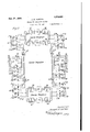
- Fig. 6 shows a type of repeater in which, depending on the connection of the leads, either the two-way repeater THE, TRW or the repeater RE, RW can be used for carrier telegraph or carrier telephone transmis sions. It will be assumed that Fig. 6 is substituted for Fig. 3 in the circuit layout previously considered, and conditions will be considered according as both carrier telephone and carrier telegraph are transmitted or carrier telegraph without carrier telephone, or carrier telephone without carrier telegraph.
- the upper and the lower repeater sets of Fig. 6 are entirely similar.
- the repeater element directed for transmissions from west to east is included between two bandsuppression type of filters 1'28 and 129 or 130 and 131.
- These filters have the characteristic property of freely transmitting currents of all frequencies from zero to a predetermined upper limit, in this case 5,500, and from a predetermined lower limit in this case 21,333 upwards to infinity, while attenuating and substantially suppressing currents of all frequencies included. between the two predetermined limits.
- these filters may each be replaced by two filters in series, one of which is a low pass filter having a limiting frequency of 5,500, and the other which is ahigh pass filter having a limiting frequency of 23,333.
- the repeaters TRW and RW arerespectively included between pairs'of band filters 132, 133 and 134, 135 having the limiting frequencies of 6,500 and 18,666.
- frequencies are transmitted eastward through the telegraph side of the circuit ranging in frequency from the base frequency of 3,333 to the frequency of channel S or 5,500, whereas waves are transmitted westward ranging in frequency from the frequency of channel ES, It or 6,500 to the frequency of channel E8 and R 'or 9,030.
- Eastward high frequency telephone transmissions received at the repeater station have frequencies from 21,333 upwards as in dicated at Figs. 2 and 4, while westward telephone transmissions have frequencies from 10,000 to 18,666 except when no high frequency telegraph c annels are in use).
- the eastward carrier telephone transmissions having the frequencies indicated upon arriving at the repeater station are directed by the filter 54 through jacks J and J to the lower repeater set where they are transmitted by filters 130, 131 and repeater RE.
- Westward carrier telephone transmissions having the frequencies indicated are directed by the filter 64 through jacks .P and J to the lower repeating set where they are transmitted by the filters 134, 135 and repeater RW. Since both two-way repeater sets are alike in the form shown in Fig. 6, it is evident that jack J could inst as well have been tied to jack J and jack J to J, provided at the same time jack J and J 'were tied together and Jacks J and J were tied together.
- the filters 53, 54 and 63, 64 are eliminated as previously described, and the jacks J and J are tied together, and J and J are tied together or if for any reason it is'p'referred, jacks J and J may be tied together and jacks J and J 21 may be tied together.
- the upper repeater set of the figure serves to repeat eastward and westward telegraph transmissions in the manner previously described.
- the filters 53, 54 and 63, 6+1 are eliminated from the circuit and the jacks J and J are tied respectively, to the jacks J and J" or they may be tied respectively to the jacks J and J lVith the repeater arranged as shown in Fig. 6, the harmonic generator could be at the west terminal stationand it will be seen that the base frequency 3,333 could be transmit ed through the eastward repeater (or THE).
- a path which the base frequency takes at the repeater station is therefore from jack J to jack J, filter 130, repeater RE, filter 131, jack J 21 to J, etc.
- the westward telephone transmissions are repeated in the same direction ex cept that instead of passing through the filters 54 and 64, they pass directly from jack J to J, and from J to J
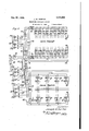
- Fig. 7 shows a modified filter arrangement for a terminal station which under certain conditions it may be preferred to use.
- the main point of difference between the circuit of this figure and the circuits shown in the figures previously described is that in the arrangement of Fig.
- the grouping filter and the corresponding filters ofv the terminals of the several channels cooperating with the grouping filter have different terminal relations from those shown in the other figures.
- Fig. 4 for example, it will be seen that the outgomg terminals of filters 85 to 88 inclusive, are connected in parallel'to the terminals of the jack J and also to the terminals of the filter 82.
- Fig. 7 the filter arrangement for the terminal apparatus of two-channels is diagrammatically shown and'it will be seen that a series connection of the filter termination of this figure rather than a parallel connection is employed.
- These two two-way channels are arranged main line ML, and the low frequencylines L and L respectively.
- the upper channel of the figure uses a carrier frequency of 6,000 indicated as being derived from the source 0, while the lower channel of the figure uses a frequency of 9,000 derived from a separate oscillator O'.
- a band filter 152 Inserted between the modulator M of the upper channeL and the circuit 159, which at 156 is coupled with the common line ML, is a band filter 152 designed to pass selectively the frequencies necessary for signaling through this transmitting channel, and the modulator M of the lower channel is similarly connected through a filter 153 designed to pass selectively the frequencies used by this transmitting channel.
- a series circuit is therefore formed including the primary of coupling 156, one side of the line 159. the terminal 2 of filter 158 and the terminal section thereof to terminal 1, terminal 2 of the filter 153 and the terminal section thereof to the terminal 1, the opposite side of the line 159 and the terminal :3 of filter 152 and the end section thereof to terminal 1.
- each filter has a high terminal impedance across 1 and 2 for the frequency of the wave which it is designed to transmit between the terminals 1, 2 and the terminals 3, 4, while its end section has a low impedance for currents of the frequencies transmitted by all of the other filters with which it is connected.
- the attenuation from terminals 1, 2 to 3, 4 or vice versa of each filter is low for a. certain frequency range which it is desired to transmit selectively but is high to waves of other frequencies.
- the waves leaving the modulator M of the lower channel, and selectively transmitted through the filter 153 pass readily through the end section of filter 158 adjacent to the terminals 1 and 2 thereof, and through the end section filter 152 adjacent to the terminals of 1 and 2 thereof, and the coupling 156 to the line.
- a wave incoming from the mainline to be received by the lowermost channel passes through the coupling 156, the end section of filter 152 adjacent to the terminals 1 and 2, the corresponding end section of filter 153, but meets an impedance across the terminals 1 and 2 of filter 158 which is equal to thecharacteristic impedance of the line.
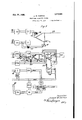
- Fig. 8 shows a'low pass filter of the type which would be used at the west terminal station if this station has its filters arranged as indicated in Fig. 7, since the grouping filter at the west station is a low pass filter as indicated at 32.
- the filter of Fig. 8 will be connected in place of the filter 158 of Fig. 7, its terminals 1, 2 and 3, 4 indicating the manner in which it would be connected in the circuit to re place filter 158.
- a main line serving as a transmission path for a plurality of communication channels usin respectively different frequencies comprised in a. definite frequency range for transmitting in one direction over the line and a different plurality of channels using individual frequencies lying in a different frequency range for transmitting in the other direction over the line, the channels for one direction of transmission terminating at a given station on the line in transmitter sets connected through suitable filter circuits to a transmit-ting branch of the line at that station and the channels for the other direction terminating in receiving sets connected through suitable filter circuits to a receiving branch of the line, the transmitting and receiving branches being located at the same station and conductively connected to the line, a grouping filter included in the receiving branch between the line and said receiver sets and arranged to pass the frequencies employed by all the channels to which said receivers belong but to exclude from the receiver branch the frequencies in the transmitting branch at-said station, the output terminals of the transmitting filter circuits being connected in parallel and to the line terminals of the grouping filter While the opposite terminals of
- a line for transmitting currents of a plurality of frequencies for different messages a transmitting branch for said line, a filter a plurality of receiving channels connected to said filter to receive currents of different frequencies transmitted through it, said transmitting branch and filter being connected to the same end of said line and having terminations in series with each other.
- the frequencies employed by all of the transmitters as a. group being comprised in a different range from the frequencies employed by the receivers as a group, and a filter associated with each branch,the filter associated with the transmitting branch being connected between the transmitting sets and the line and arranged to pass currents of the frequencies transmitted by the transmitting sets and to exclude from the transmitting sets the currents of the frequencies transmitted over the line to the receiving sets, and the filter associated with the receiving branch being connected between the receiving sets and the line and arranged to pass currents of the frequencies employed by the receiving sets and transmitted thereto over the line and to exclude from the receivingsets the currents transmitted from the transmitting sets.
- a multiplex si naling system having a group of carrier te egraph two-way channels employing a plurality of different frequencies within a given range, a group of carrier telephone two-way channels employing frequencies included in a ditferent range, a transmission line common to and associated with the carrier telephone and telegraph two-way channels, alternative circuit connections for permitting both carrier tele graph and carrier telephone transmission simultaneously over said line or either carrier telephone or arrier telegraph transmissions separately, grouping filters connected to the line for separatin to the terminal apparatus the carrier telegraph and telephone frequencies respectively, and means included in said alternative circuit connections for making available for carrier telegraph transmissions when no carrier telephone transmission is taking place at a station, frequencies that are normally used only for carrier telephone transmission, and for making available for carrier telephone transmission when no carrier telegraph is being transmitted, frequencies that are normally devoted to carrier telegraph transmission.
- a carrier composite telephone and telegraph system in which a frequency range below a definite ployed for carrier telegraph transmissions and frequencies above said limiting frequency are employed for carrier telephone transmissions, sources of current of suitable frquencies and terminal apparatus for both kinds of transmissions, and circuit connec tions for disabling said carrier telegarph terminal apparatus and for permitting an additional carrier telephone channel to be used employing frequencies lower than said limiting frequency.
- a carrier composite telephone and telegraph system in which a frequency range below a definite limiting frequency is em ployed for carrier telegraph transmissions and frequencies above said limiting frequency are employed for carrier telephone transmissions, sources of current of suitable frquencies and terminal apparatus for both kinds of transmissions, and circuit connec-' tions for disabling said carrier telephone terminal apparatus and for permitting an additional carrier telegraph channel to be used employing frequencies higher than said limiting frequency.
- a composite carrier telephone and telegraph system having in combination a. source limiting frequency is emof waves of a base frequency, a plurality of the telephone channels being grouped within a range different from that for the telegraph channels, a transmission line with which the channels are associated, means to maintain at the terminal and intermediate points on the line a selective path for the 7 telegraph transmissions, and circuit connec tions for transmitting base frequency waves through the selective path with the telegraph transmissions.
- a composite carrier telephone and 30 telegraph system having a plurality of telegraph channels, a plurality of telephone channels, means to supply to the telegraph channels waves of ditierent frequencies within a given range, means to supply to the telephone channels carrier waves of different frequencies outside said given range, means to furnish a wave of a frequency within said given range for the operation of the telephone channels, alternative circuit arrangements whereby when the carrier-telegraph equipment is idle but the carrier telephone channels are being used, the one frequency wave is transmitted through the carrier telephone circuits and when both carrier telegraph and carrier telephone channels are being used, the one frequency wave is transmitted through the carrier telegraph circuits and when no carrier telephone china-' nel is being used, the one frequency wave is connectible for use as rier wave.
- a composite carrier telephone and carrier telegraph system having a plurality a telegraph carof carrier telegraph channels, a plurality of carrier telephone channels, means to supply to the channels carrier waves of different frequencies, circuit connections whereby the telephone and telegraph channels may be used simultaneously or alternatively, cir-,
- a composite carrier telegraph and carrier telephone system in which the utilized frequencies comprise a range devoted to a group of carrier telegraph channels all transmitting in one direction and an adjacent range devoted to a group of carrier telephone channels all transmitting in the same direction as said carrier telegraph channels, said system having filtering means for separating carrier telegraph transmissions from carrier telephone transmissions, and means fordlsabhng a portion at least of the channels devoted to one of said kinds of transmission and for extending the number of channels devoted to the other kind of transmission to include frequencies in the range of the disabled channels.
- carrier telephone channels In a carrier wave transmission system, carrier telephone channels, a source of base frequency, means to transmit a wave of the base frequency through the system, means to derive from said source carrier waves of different frequencies for the respective carrier telephone channels, a mid-line repeater for said system having a two-way selective repeating path for said carrier telephone channels and another selective path for other frequencies including a one-way repeating path for said base frequency, means for disabling at will said other selective repeating path and for transmitting said base-frequency wave through the same repeater that is used for the carrier telephone transmis- SlOIlS.
- each repeater included in a different selective path, means for transmitting a control wave of definite frequency in either direction through said system, means operative when both repeaters are in circuit for providing a path for said control wave only in one direction through said system including the selective path of one of said repeaters, means for disabling said repeater and for providing a path through another repeater in the opposite direction for said control wave.
- a selective path for a group of carriertelephone channels for transmitting in one direction between said stations, an oppositely directed path selective to other frequencies used for transmission in the other direction between said stations, means f r deriving the carrier frequencies for said carrier telephone channels from a wave of base frequency-included in the range of said other frequencies, means to disable the second mentioned selective path and render the first mentioned selective path available for the transmission of the base frequency, and means to'transmit a wave of base frequency from either station according as said path is disabled or not.
- two line sections means to transmit acontrol wave in either direction through said systern, an east repeater and a west repeater similarly connected in parallel with each other between the two line sections, saidrepeaters having selective amplifying paths of overlapping frequency range including the frequency of said control wave, filters for preventing local circulation of amplified energy through said repeaters and for permitting transmission ofsaid base frequency we t g ne at ai ep ters e both repeaters are operative, means for disabling said one repeater and for altering the connection of said filters to permit the other repeater to transmit said base frequency wave in the opposite direction through the system.
- a composite signaling system arranged to transmit currents of at least three distinct frequency ranges assigned for at least three separate classes of signaling, filter systems for separating each of said frequency ranges from the others, and means to extend the frequency range used for one class of signaling to include neighboring frequencies of a range assigned for another class of signaling in case said neighboring frequencies are at the time not being used for the class of signalingfor which they are assigned.
- a composite carrier system in which a range of frequencies is utilized by twoway carrier telegraph channels and a separate range is utilized by two-way carrier telephone channels, a mid-line repeater circuit comprising two two-way repeaters in parallel, grouping filters for separating carrier telegraph transmissions to one of said repeaters and carrier telephone transmissions to the-other, other filters for directing the transmissions of the same direction through one repeater element and transmissions of the other direction through the other repeating element of both the carrier telegraph and the carrier telephone repeaters, and circuit connections for including either repeater together with its direction-determining filters in circuit with either grouping filter.
- a composite carrier telegraph and carrier telephone system in which a lower range of frequencies is assigned for carrier telegraph transmissions east-ward, a central range is assigned for carrier telegraph and carrier telephone transmissions westward, and an upper range is assigned for carrier telephone transmissions eastward, a repeating circuit for said system comprising a pair of duplicate two-way repeaters in parallel, each two-way repeater having an eastward selective repeating path for frequencies of both said lower range and said upper range and a westward selective repeating path for frequencies of said central range, grouping filters for separating all of the carrier telegraph transmissions as a group from all of the carrier telephone transmissions as a group, circuit arrangements for connecting either two-way repeater to either grouping filter, and means for disabling certain of the transmission channels and one of said repeaters and for connecting theother repeater in the system independent of said grouping filters.
Landscapes
- Engineering & Computer Science (AREA)
- Computer Networks & Wireless Communication (AREA)
- Signal Processing (AREA)
- Cable Transmission Systems, Equalization Of Radio And Reduction Of Echo (AREA)
Description
Filed July 29, 1921 .I A A VTEA Mme/7 fan fi a ,M m m N M w 0 m M J M Q m Q i R w j W L m W .1% E Wk Feb. 2311926; I 1,574,484 HORTON "MUL'IIPIEEX SIGNALING SYSTEM Filed July 29, 1921 '7 Sheets-Sheet 5 4 HCE Feb. 23 ,1926. v I 1,574,484
J. W. HORTPN v HULTIPLEX SIGNALING- SYSTEM J. W. HORTON MULTIPLEX SIGNALING SYSTEM Filed July 29, 1921 '7 Sheets-Sheet 7 PM... Feb, 23, 1926.
UNITED STATES PATENT OFFICE.
JOSEPH W. HORTON, OF EAST ORANGE, NEW JERSEY, ASSIGNOR TO WESTERN ELEC- TRIO COMPANY, INCORPORATED, OF NEW YORK, N. Y., A. CORPORATION OF NEW YORK.
MULTIPLEX SIGNALING SYSTEM.
Application filed July 29, 1921. Srial 110. 488,297.
naling Systems, of'which the following is a full, clear, concise, and exact description.
This invention relates to a multiplex sys-.
tem employing a plurality of currents or waves of different frequencies for the transmission of signals or for similar purposes.
The invention provides a system of this general character which is flexible in use 1n that it may be readily altered to suit different kinds and conditions of transmission;
which is adapted to work with existing sys-- tems; and which is particularly eflicient in performing the functions for which it was created, which functions will be set forth in the description to follow.
Its objects are obtained by novel associations of circuit elementsincluding articularly filters or other selective circuits, sig naling terminal apparatus, repeaters and switching arrangements all of which may in themselves be old but which unite in the system of the invention in new ways to produce desirable results not heretofore reallzed.
In the preferred embodiment of the invention, multiplex signal transmission is accomplished over a common transmission medium or line. Transmission of several kinds of signals may be carried on at the same time and in both directions through the system, and these different kinds of signals and the different directions of transmission are distinguished by the different frequencies that are employed. Wave filters and tuned circuits are used to separate the various distinctive frequencies one from another, and a minimum number of such cirvcuits is used to separate efficiently the several rier transmissions.
transmissions. Normally, transmissions of an ordinary telephone line such as ordinar telephone, Morse telegraph, and other signa ing currents within or below the ordmary telephone range are se arated from the carhe carrier transmissions comprising telephony and telegraphy are separated from each other. In some cases certain distinctive frequencies used for carrier telephony are grouped with the carrier telegraph distinctive frequencies for selective purposes. Switching means permit of increasing the number of'carrier telephone transmissions if for any reason the carrier.
telegraph channels are in operation at the time.
. Other objects of the invention, and other features of the preferred embodiment thereof will appear from the detailed description of the system shown in the accompanying drawing.
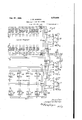
Figs. 1, 2, 3-, 4 and 5, when arranged according to Fi 9, show one embodiment of the invention 1n which Fig. 1 shows the carrier telegraph and carrier telephone apparatusat'one terminal station; Fig. 2, the selective circuits at the same station; Fig. 3, the apparatus and selective circuits at a midline repeater station; Fig. 4, the selective circuits at the. other station; and Fi 5, the
carrier telephone and carrier te egraphterminal apparatus at the other station; Fig. 6 also shows the apparatus and selective circuits at a mid-line repeater station which differs slightly from that ofFig. 3, and may be substituted therefor to constitute a modified system; Fig. 7 shows a modified arrangement of terminal apparatus and selective circuits; Fig. 8 shows a filter arrangement which ma be substituted for one of the filters of Fig.
The invention will be more clearl understood from a detailed description 0 the aparatus and operation of its preferred emodiment in connection with the drawings.
Referring now to the system shown in Figs. 1, 2, 3, 4: and 5 arranged according to. Fig. 9, the terminal station of Figs. 1 and 2, hereinafter called the west station, is connected to the terminal station shown in Figs. 4. and 5, hereinafter called the east station, by. means of a common transmission line -ML. In the system under consideration, a
prising a hi h pass filter 26, and a low passfilter 27. he'se filters and others used throughout this system unless otherwise specifically mentionedare of the type disclosed in G. A. Campbell Patent zit-1,227,113, May 22, 1917. Filter 26 is adapted to pass with substantially negligible attenuation all currents having frequencies of 3,333 cycles and above, and to greatly attenuate currents having a frequency less than 3333 cycles, while filter 27 is adapted to pass with substantially negligible attenuation all currents having frequencies of 3000 cycles or less and to highly attenuate all currents having frequencies above 3000. Such an arrangement of filters is shown in Fig. 15 of a paper entitled Carrier current telephony and telegraphy by Colpitts and Blackwell, published in the Transactions of the American Institute of Electrical Engineers, volume 4.0. These filters serve to separate the normal transmission of an ordinary telephone line L from the carrier transmissions of the carrier circuit 0C In order to separate the carrier telegraph transmissions from the carrier telephone transmissions, filters 28 and 29 are provided. Filter 28 is a low pass filter adapted to pass with substantially negligible attenuation, frequencies of 9030 cycles and under, and to highly attenuate all frequencies above that value. Filter 29 is a high pass filter adapted to pass with substantially negligible attenuation, frequenciesof 10,000 cycles and above, and to highly attenuate all. frequencies below that value. These filters will hereinafter be called carrier grouping filters.
For the carrier telegraph transmissions, filters 30 and 31 are provided to separate the frequencies used for transmission from the west station from those used for reception thereat. Filter 30 is a low pass filter adapted topass with substantially negligible attenuation, frequencies of 5500 cycles and lower and to highly attenuate all frequencies above 5500 cycles. Filter 31 is a high pass filter adapted to pass the fre' quency of 6500 cycles, and all frequencies above that value, and to highly attenuate all frequencies below 6500 cycles. These filters will hereinafter be called carrier telegraph grouping filters.
Filters S to S inclusive, are provided to separate the frequencies used for carrier telegraph transmitting at the West station. It is not necessary to use filters for this purpose, and in the preferred form tuned circuits are used instead of wave filters to separate the frequencies used for carrier telegraph reception. At the west station selec tive circuits R to R inclusive are employed. The carrier telegraph terminal apparatus.
shown in Fig. l-is that required for one duplex telegraph circuit and is similar to the terminal apparatus shown in Fig. 55 of the Colpitts and Blackwell paper, The sending circuit, comprising the oscillater 0, amplifier A, and sending relay 8, is
supra.
connected to the sending selective circuit S by conductors 5. The receiving circuit, comprising amplifier A detector TD and receiving relay 6, is connected to the receiving selective circuit R by conductors 7. The sending relay 8 and receiving relay 6 are associated with an ordinary Mors'e telegraph line 9 and an artificial line AL in the well known manner for duplex operation. Similar carrier telegraph apparatus may be connected to each of the other sending selective circuits S to S inclusive, and receiving selective circuits R to R inclusive to provide additionalcarrier telegraph channels. Selective circuits S and B may be used to provide an additional carrier telegraph duplex channel under certain circumstances which will be explained hereinafter.
The frequencies used by the several channels for carrier telephone transmission from .the west station are separated from one another by band filters 33 to 36 inclusive, and the frequencies used for reception for the several channels at the same station are separated by band filters 37 to 40 inclusive.
Each of these filters is adapted to pass with substantially negligible attenuation a band of frequencies characteristic of the telephone transmission of that channel and to highly attenuate all frequencies outside of that band. Band filters 36 and 40 are shown by dotted.lines, since they are not used under certain circumstances hereinafter to be described.
The carrier telephone apparatus is similar to that of Fig. 49 of the Golpitts and Blackwell aper, supra. An ordinary telephone line is associated with a carrier telephone transmitting circuit TC, and the carrier telephone receiving circuit RC by means of a conjugate transformer or hybrid coil 10 with the low frequency balancing net N. Transmitting circuit TC comprises a modulatorM and transmitting amplifier TA and is connected to the transmitting band filter 33 by conductors 11. The receiving circuit RC, comprising a detector 1), a detector amplifier DA and a low pass filter LPF, is connected to the receiving band filter 37 by means of conductors 12.
For the carrier telephone operation accord ing to the system illustrating and new being described, each channel is supplied with a frequency which is a harmonic of a base frequency which in this case is 3,333 cycles. This base frequency together with the harmonics thereof is supplied by the harmonic vided. For transmission purposes the modulator M is supplied with carrier current of one carrier frequency bythe sending harmonic amplifier SHA while the demodulator D is supplied with current of one carrier frequency by the receiving harmonic amplifier RHA. It is understood that at some suitable point in the amplifier circuits SHA and RHA a selective circuit for one particular carrier frequency is em- )loyed, as for example between the ampliner element and the branch HCW or between the amplifier element and the modulater or detector. It is not deemed necessary to illustrate the details of such a cir-- cuit since it is well known. Similar sending and receiving harmonic amplifiers and selective circuits are provided'for each 'carrier channel. All of these amplifier circuits are connected in parallel to a common circuit terminating 1n the, twin jacks J By means of twin plugs P and P and twin conductor cord 13, twin jacks J may be connected either to the harmonic generator through twin jacks J 2 or to the harmonic regenerato-r HRG through twin jacks J By means of twin jacks J 4 to J 9 inclusive, and twin plugs P to P inclusive and interconnecting two-conductor cords to 37 in clusive, provision is made to connect either the carrier telegraph terminal alone, or the carrier telephone terminal alone, or both the carrier telegraph and carrier telephone terminals together to the common carrier circuit CO The-various connections will be described more in detail hereinafter.
Referring now to Fig. 3, line L and the common carrier circuit C0 are connected to the common line ML by a high-frequency composite set to the main line ML at the left, comprising the high pass filter 51- and the low' pass filter 52. Filters 51 and 52 are s mllar respectively to filters 26 and 27. Carrler grouping filters are also provided and comprise a low pass filter 53 and a high pass filter 54. Filters 53 3.116154 are similai respectively to filters 28 and 29 of Fi 2. For repeating carrier telegraph signa s east and west repeater elements TRE and TRW respectively are provided. Re
are described in connection with Figs. 21
and 22 of the Colpitts and-Blackwellpaper,
supra. Carrier telegraph transmissions east are separated from transmissions west by low pass filters 55 and 56 and high pass filters 57 and 58 respectively. Filters 55 and 56 are adapted to pass the same range of frequencies as filter 30 of Fig.2, and filters 57 and 58, the same range of frequencies as filter 31 of Fig. 2.
The carrier-telephone repeater elements RE and RW are provided for repeating transmissions east and transmissions west respectively. These elements may be similar to repeater elements TRE and TRW' of the carrier telegraph repeater. High pass filters 59 and 60 and low pass filters 61 and 62 I are provided to separate the carrier telephone transmissions east from the transmissions west. Filters 61 and 62 are adapted to pass the same range of frequencies as filter 32 of Fig. 2. Filters 59 and 60 are adapted to pass all frequencies from 21333 cycles upwards inclusive, and therefore are adapted to pass all of the frequencies which are passed by filters 33 to 36 inclusive of Fig. 2. The carrier grouping filters 63 and .64 separate the carrier telegraph transmissions from the carrier telephone transmissions on the right of Fig. 3. Filters 63 and 64 are similar to and adapted to pass the same range of frequencies as filters 28 and 29 respectively of- Fig. 2. A high frequency composite set compris-, ing high pass filter 65 and low pass filter 66 is provided to connect the common carrier circuit CC and the ordinary telephone line .L to the common line ML. High pass filter 65 and low pass filter 66 are similar respectively to high pass filter 26 and low pass filter 27 of Fig. 2. Twin jacks J to J inclusive on the left, and twin jacks J to .J inclusive on the right, and twin plugs P to P on the left, and twinplugs P to P on the right, together with twin conductors 67 to 69 inclusive on the left, and-twin conductors 70 to 72 on the right, provide means for connecting. the carrier telegraph repeater, and the carrier telephone re- -peater to the common carrier circuits 0C and CO in several ways hereinafter to be described. a
The east station is quite similar to the west station. The high frequency composite set comprising the high pass filter 76 and the low pass filter 77 connects the common carrier circuit CC and the ordinary telephone line L to the common line ML. Filters 76 and 77 correspond respectively to filters 26 and27 of Fig. 2. Low pass filter 78 and high pass filter 79 are the carrier grouping filters of the east statiomand correspond'respectively to filters 28 and 29 of the west station. Low
It will be noted that filters 32 and 82 are each in the receiving branch of their respective stations. One important purpose served by these carrier telephone'grouping filters is the reduction of any tendency for cross talk between the different channels due for example to energy from any of the transmitting circuits 3336 finding its way through any of the receiving filters 37-40. These receiving filters have their terminal sections all connected to the common ter-' minal circuit, to the other branch of which the transmitting channels are connected. The currents impressed on this terminal circuit from the transmitting channels are of relatively high amplitude and any filters which are to be employed to keep these currents out of the receiving channels must offer very high attenuation tothe currents of these frequencies. If the channel filters 3740 alone were relied on for this purpose theymust each be made to have very high attenuation to foreign frequencies and this would incur considerable expense. However by using a grouping filter 32 of moderately high attenuation for the transmitting frequencies, the channel filters 3740 need have only moderatelyfhighattenuation for foreign frequencies. {They will then effectively separate the received frequencies which are of relatively low am-,
plitude, and the attenuation-which they otter to the transmitting frequencies together with the grouping filter 32 can still be very high without necessitating the costly construction required without the grouping filter.
\Vhere several filters such as 3740 are ".onnected in common to a line it is ditficult to make their total resultant impedance have the desired value while still giving the indi vidual filters the most advantageous attennation and impedance characteristics. A further advantage of using a groupin filter such as 32, therefore, is that in COIISIdBI'lDg the terminal impedance of the receiver carrier branch, the impedance of a single filter instead of the impedance of a number of filters together can be dealt with. For this reason it may be advantageous at times to use a grouping filter 32 in the transmitting branch also, but since this filter would be used largely for the sake of its impedance characteristics and would not be asimportant on account of its attenuation properties asis a grouping filter in the receiving branch it could be omitted ordinarily from the circuit. A corresponding filter is shown at 82 Selective circuits ES to ES inclusive correspond to the sending selective circuits S to- S of the west station and cooperate with the receiver selective circuits R to R inclusive of that station. The receiving selective circuits EH to ER inclusive of the east station correspond to the receiving selective circuits R to R inclusive of the west station and cooperate with the sending selective circuits S to S inclusive of that station. The carrier telegraph terminal apparatus of the east station com rises the sending relay 101 associated wit the os cillator O, the amplifier A connected to the tuned circuit ES by conductors 83, and the receiving relay 102, detector TD receiving amplifier A connected to the receiving selective circuit ER by conductors 84. An ordinary telegraph line 103 and an artificial line AL are associated with the sending relay 101, and receiving relay 102 by the well known duplex telegraph circuit.
Band filters 85 to 88 inclusive are connected in the transmitting circuits of the several telephone channels and correspond to band filters 33 to 36 inclusive of Fig. 2, and cooperate with band filters 37 to 40 inelusive of Fig. 2. Receiving band filters 89 to 92 inclusive of theeast station 001 respond to receiving band filters 37 to 40 inclusive of the-west station. At the east station the ordinary telephone line is connected to the transmitting circuit TOE and the receiving circuit RCE bythe hybrid coil 104 and its balancing network N. The transmitting circuit TCE and the receiving circuit ROE are similar to the transmitting circuit TC and receiving circuit RC respectively of the west station and comprise respectively a modulator M and an amplifier TA connected to filter 85 by conductors 93 and demodulator D, a demodulator amplifier DA, and a low pass filter LPF connected to filter 89 by conductors 94. A sending harmonic amplifier SHA and a receiving harmonic amplifier RHA are connected respectively with the modulator M and the detector D. The harmonic generator HG, the harmonic regenerator EHRG, the transmitting base frequency amplifier ETBA, and a receiving base frequency amplifier EBA corresponding to the harmonic generator HG,the harmonic regenerator HRG, the transmitting base frequency amplifier WTBA, and a receiving base requency amplifier VVBA on the west station are provided at the east statio By means of twin jacks J and two-conductor cord 105, the harmonic generator HG, or the harmonic regenerator EHRG may be contraced.
Assuming first that it is desired to use the common line ML for ordinary transmissions and bothcarrier telephone and carrier telegraph transmissions, the transmission circuits will be completed by inserting the twin plugs P to P inclusive, respectively, into twin jacks J to J inclusive. Morse telegraph and ordinary telephone and telephone signaling transmissions, the essential frequencies of which are no greater than 3000 cycles follow a path which may be traced y from low frequency line L of Fig. 2, through low pass filter 27, common line ML of Fig. 2, common line ML of Fig. 3 through low pass .filter 52 to the ordinary telephone line L This line L may terminate in a telephone exchange or a subscribers station, or it may be connected by suitable apparatus to the ordinary telephone line L in which case the transmission would pass through low pass filter 66, common line ML at the right of Fig. 3, common line MLof Fig. 4, through low pass filter 77 of Fig. 4, to the ordinary telephone line L. Current used for these transmissions would be excluded fromthe common carrier circuits CO CC, CC and CC -by high pass filters 26, 51, 65 and 76, respectively.
Carrier telegraph transmission from the line 9 at the west station to 'line103 at the east station will now/be traced. Such a transmission in the form of dots and dashes with corresponding impulses of current in line 9 will operate sending relay 8 in a well known manner. The oscillator O is normally generating current of 3810 cycles. This current is normally short-circuited through condensers 14 and the contact of sending relay 8. The operation of sending relay 8 in response to the dot and dash impulses removes this short-circuit and allows impulses of carrier current to pass to the amplifier A from which it flows through conductor-s 5, transmitting sending selective circuit S transformer 41, low pass filter 30, twin jacks J twin plugs P conductors of cord .35, twin plugs P, twin jacks J", low pass'filter 28, twin'jacks J, twin plugs P, conductors of cord 36, twin plugs P, twin jacks J, common carrier circuit CC, high pass filter 26,'common line ML of Fig.2 to the common line LIL at the left side of Fig. 3, high passfilter 51, common carrier circuit CC, twin jacks J twin plugs P conductors of cord 68, twin plugs P twin jacks J, low pass filter 53, twin jacks J twin plugs P conductors of cord 67, twin plugs P twin jacks J low pass filter 55, repeater element TRE, low pass filter 56, twin jacks J twin plugs P conductors of cord 70,
- twin plugs P twin jacks J low pass filter 63, twin jacks J twin plugs P conductors of cord 71, twin plugs 1", twin jacks J common carrier circuit CC, high pass filter 65, common line ML at the right side of Fig. 3 to common line ML of Fig. 4, high pass filter 76, common carrier circuit CC, twin jacks J twin plugs P conductors of cord 95, twin plugs P, tw-in jacks J low pass filter 78, twin jacks J twin plugs P conductors of cord 96, twin plugs P twin jacks J low pass filter 80, transformer 98,
receivin selective circuit ER conductors 84 of 'Fig. 4 to conductors 84: of Fig. 5, amplifier A detector TD, and receiving relay 102. Receiving relay 102 responds to impulses of current from the detector TD under control of the carrier current impulses to close its contact. The closing of the contact of receiving relay 102 sends impulses of current from source 106 to the telegraph line 103. Theseimpulses of current will operate telegraphic receiving apparatus in the well known manner,
Impulses of current in line 103 corresponding to signals originating at the east station are transmitted to the West station in a somewhat similar manner now to be described. The carrier frequency usedfor this transmission is 9030 cycles. The oscillator of Fig. 5.generates current 9030 cycles 'which is normally short circuited through condensers 107 at the contact of sending relay 101. Sending relay 101 operates in responseto impulses of current in line 103 corresponding to dots and dashes and removes a short clrcuit in the output of oscillator 0. These impulses are transmitted to the west station through the amplifier A of Fig. 5, conductors 83 ofFigs. 5 and 4, sending selective circuit ES, transformer 99, high pass filter 81, twin jacks J twin plugs 1 conductors of cord 96, twin plugs P twi'n jacks J low pass filter 78, twin jacks J twin plugs P conductors of cord 95, twin plugsP, twin jacks Jff, common carrier circuits CC, high pass filter 76, common transmission line ML of Fig. 4, common ductors of cord 71, twin plugs P twin jacks J low pass filter 63, twin jacks J twin plugs P cord 70, twin plugs P twin jacks J high pass filter 58, repeater element TRW, high pass filter 57, twin jacks J, twin plugs Pf, cord 67, twin plugs P twin jacks J low pass filter 53, twin jacks J twin plugs P cord 68, twin plugs P,
twin jacks J common carrier circuit CC? o high pass filter 51,.common line ML at left side of Fig. 3, common line ML of Fig. 2, high pass filter 26, common carrier circuit CC twin jacks J, twin plugs P cord 36, twin plugs P, twin jacks J low pass filter 28,- twin jacks J twin plugs P, cord 35, twin plugs P twin acks J high pass filter 31, transformer 4-2, receiving selectivecircuit R conductors 7 of Figs. 2 and 1, receiving amplifier A detector TD to receiving relay 6. The operation of receiving relay 6 in response to impulses of current received by detector TD, closes a circuit from a source 15 to the telegraph line 9 and operates telegraphic receiving apparatus in a well known manner.
Typical carrier telephone transmissions will now be traced through a circuit. The base frequency for all the currents is generated in the harmonic generator HG of Fig. 1. Twinplugs P? are inserted in twin jacks J wh le twin plugs P are inserted in twin jacks J to complete a circuit for carrier current from the harmonic generator HG of Fig. 1 to the modulator M and detector D in the same figure. Base frequency and its harmonics are transmitted from the output of the harmonic generator HG through twin jacks J twin plugs P cord.13, twin plugs P twin jacks J 3 to the harmonic circuit HCVV. From this circuit, current of proper frequency is transmitted to the modulator M through the harmonic amplifier SHA in the manner shown in Fig. 4.9 of the Colpitts and Blackwell paper. In a similar manner carrier current for the demodulator D is received from the harmonic circuits HCW through the harmonic amplifier RHA. Thebase frequency from the harmonic generator HG, Fig. 1 is transmitted to the east station of Fig. 5 through the base a frequency amplifier WT BA, conductors 16 of Figs. 1 and 2, filter 33, line side of transformer 41, thence to the line side of transformer 98 of Fig. 4, through the same circuit tra ed for the carrier telegraph transmission from west to east, filter 100, conductors 108 of Figs. 1 and 5, base frequency amplifier EBA to the harmonic regenerator EHRG. A circuit for the output energy for the harmonic regenerator EHRG to the carrier terminal apparatus is completed by inserting twin plugs P into twin jacks 29, and twin plugs P into twinjacks. J forming a path through cord 105 to the common harmonic circuit HOE. From this circuit, current is supplied to the modulator M and the detector D through the sending harmonic amplifier SHA, and the receiving harmonic amplifier RHA, respectively.
7 For carrier telephone transmission from west to east on the channel shown,-a carrier frequency of 23,333 cycles is used. This car rier when modulated in accordance with "speech results in two side bands offrequencuss, the essential frequencies of which for voice transmission extend over approximately 2,000 cycles on either side of the carrier frequency. For transmission from west to east, the lower side band only is transmitted.
Current in line L corresponding to the conversation being transmitted passes through hybrid coil 10, the transmitting circuit TC into the modulator M-where it modulates the 23,333 cycle carrier current received from the sending harmonic amplifier SHA. Carrier current modulated in accordance with speech is transmitted from the modulator M through the modulator amplifier TA, conductors 11 of Figs. 1 and 2, band filter 33, twinjacks J twin plugs P, cord 37. twin plugs P, twin jacks J high pass filter 29, twin jacks J, twin plugs P, cord 36, twin plugs P twin jacks J, common carrier circuit CC", high pass filter 26, common line ML ofFig. 2, common line ML on the left side of Fig. 3, high pass filter 51, common carrier circuit CC, twin jacks J, twin plugs P", cord 68, twin plugs P twin jacks J high pass filter 54, twin jacks J twin plugs P cord 69, twin plugs 1?, twin jacks J high pass filter 59, repeater element RE, high pass filter 60, twin jacks J twin plugs P cord 72, twin plugs P twin jacks J high pass filter 64, twin jacks J twin plugs P cord 71, twin plugs P, twin jacks J common carrier circuit (30 high pass filter 65, common line ML at right of Fig.3, common line ML of Fig. 4, high pass filter 76, common carrier circuit CC", twin jacks J, twin plugs P cord 95, twin plugs P, twin jacks J high pass filter 79, twin jacks J twin plugs P cord 97, twin plugs P twin jacks J high pass filter 82, band filter 89, conductors 94: of Fig. 4 and Fig. 5 to detector D. In the detector D, modulated carrier and carrier current from the receiving harmonic amplifier RHA are demodulated and the resulting voice currents are transmitted from the output of the demodulator D through the demodulator amplifier DA and low pass filter LPF to the telephone line L.
A telephone transmission from east to west from the line L of Fig. 5 to the line L of .Fig. 1 employs a carrier frequency of 10,000, and the'upper side band comprising frequencies of 10,000 to 12,000 is transmitted. The modulator M of Fig. 5 receives a high frequency wave of 10,000 cycles from the harmonic suppl circuit HCE, and through the amplifier S A and receives incoming voice currents from the line L through the circuit TCE. The resulting modulated wave passes through the amplifier TA and the circuit 93 to the filter 85 which passes the upper side band only. This upper side band passes throu h the terminals of jack J and jack J hlgh pass filter 79, jack J 25 and J high pass filter 76, east section of the mainline ML, high pass filter 65, jacks by connecting jack I. J and J high pass filter 64, jacks J and J to the lower portion of the repeater loop including high ass filters 61 and 62, and West repeater R jacks J and J high pass filter 54, jacks J and J, high ass filter 51, west section of the main line L, high pass filter 26, jacks J 6 and J high pass filter 29, jacks J 8 and J, low pass filter 32, and band filter 37 which is selective to the frequencies comprised in this channel only, conductors 12 to the detector D, where the received upper side band interacts with a wave of the carrier frequency supplied from the branch HCW through the amplifier RHA. The resulting detected voice-frequency current is amplified at DA and is transmitted through the receiving branch RC and the low pass filter LPF to the line L As stated in the introduction, an object accomplished by the present system is a flexible arrangement of the connections whereby the circuits may readily be set to transmit current of speech fre uency, high frequency telegraph and high requency telephone as has been described. By a simple change in the circuits, as will now be described,-the system may be arranged to transmit either high frequency telegraph or high frequency telephone alone in addition to the normal or ordinary low frequency transmission. Furthermore, when only the high frequency telegraph side, or only the high frequency telephone side ofthe circuit is used alone, the number of available channels may, according to the invention, be increased by using for the high frequency telegraph, apparatus which is normally devoted to high frequency telephone transmission or vice versa as the casemay be.
If the system is to be altered fromthe condition hereinbefore described to the condition in which no carrier telephone transmissions take place, but high frequency telegraph is transmitted, it is obviousthat the grou ing filters 28 and 29, 53, 54, 63, 64, and 78, 7 9, are no longer needed. Also the circu'its'used only for high frequency telephone transmission, and shown in the lower portion of each of the figures of the drawing, may be cut out. The high frequency telegraph path is completed by inserting twin .plugs l? and P into twin jacks .J and J and, similarly using the twin plugs, J and J jack J to jack J and jack J to jack J. The path for the high frequency telegraph transmis sion through the channel connecting line 9 of Fig. 1 with line 103 of Fig. 5 is now as previously traced up to the point where thewave passed through the filters S and and reached the terminals of jack J From this point the wave passes through the bridg- 1 .ing twin plugs to the jack J and into the common carrier branch (1G and thence through filter 26, the west section of the mainline ML, filter 51, jacks J and J, filters and 56 and the east repeater TRE, jacks J and J, filter 65, east-section of the main line ML, filter 76, jacks J and J and from there on through the filter 80, as reviously traced.
igh frequency telegraph transmission in the opposite direction through the channel connecting lines 103 and 9 reaches the terminals of jack J as previously described, and thence follows the path just now traced for transmission from west to east except that the filters 58 and 57 direct the transmission in view of its frequency through the west repeater TRWV, and upon reaching the terminals of jack J*, the west transmission is selectively passed by the filter 31 into the receiving side of the telegraph circuit.
When no high frequency telephone current isbeing transmitted, the base frequency of 3,333 cycles is not needed for harmonic generation and control, and an extra carrier telegraph channel is now available using this frequency. An ordinary -Morse telegraph line 9 with its associated balancing artificial line- AL, transmitting and receiving relays 8 and 6 and detector TD may be associated with the input of amplifier lVTBA and the output of an amplifier lVBA by means of switches SW and SW This telegraph equipment is similar to that shown at the top of Fig. 1 and associated with the input of amplifier A and'the output of amplifierA When high frequency telephone current is being transmitted, the switches SW and SW are in the position shown in the drawing so that the, Morse telegraph equipment is disconnected. When no high frequency telephone current is being transmitted, the switches SW and SW may be thrown so as to connect the Morse telegraph equipment to the input of amplifier WTBA and the output of amplifier WBA, therebyrendering the base frequency channel available for the transmission of signals which modulate the base frequency wave. The wave-of the base frequency supplied from the oscillator HG and controlled in accordance with telegraph signals to be transmitted is passed to line through the amplifier WTBA of the selective circuit 33 in an entirely similar manner to the way the wave of another frequency used for telegraph telegraph equi ment for this additional channel mayv .e connected by means of switches to the input of amplifier ETBA and to the output of amplifier EBA in the manner indicated in Fig. 5. This frequency of 10,000 which with the system set for telephone transmissions is used for one of the telephone channels can now serve as a tele graph carrier frequency since the grouping filters 28 and 78 are no longer in the circuit.
\ telephone transmissions.
A second extra channel, the transmitting terminal of which is shown at S of Fig. 2 for transmitting east, and] the receiving terminal for transmissions west is shown at R, with cooperating east terminals ER and EC, may also be used when the system is set for the condition of no high frequency The reason that this two-way channel can not be employed when high frequency telephone transmission is taking place is that the grouping filters 28 and 78 are arranged to cut-ofi' at 9030 cycles, whereas the east to west side of this channel employs the frequency of 9500 cycles.
If the system is to be used for only high frequency telephone transmission in addition to the ordinary voice frequency transmissions, the "grouping filters 28 and 29, 53 and 54, etc., are not needed and the circuits devoted to telegraph transmission and comprised in the upper portion of each of the figures of the drawing can be disconnected. The path of the high frequency telephone transmissions is completed by tying jack J 9 to ,jack J by means of the twin plugs P" and P and in a'similar manner by tying across from J to J, J to J and J to J". In the condition in which both hi h frequency telephone and high frequency te egraph is being transmitted the base frequency of 3,333 cycles was generated at the west station and transmitted to the high frequency telegraph side including the upper repeater of Fig. 3 to the east station where harmonics were regenerated. This path is no longer available since the telegraph side of the circuit including the upper repeater of Fig. 3 has now been disabled. The lower or carrier telephone repeater of Fig. 3 is arranged to transmit to the east only those frequencies lying above 21333 and, therefore,
the base frequency cannot be repeated east by the repeater that is now in thecircuit. The west repeater RWV, however, is arranged to repeat frequencies below 18666, and with the type of circuit under consideration, it is necessary therefore, to generate the base frequency at the east station. For this ur pose, the harmonic generator HG of Fig. 5 is provided, and by plugging into jacks J and J with the twin plugs P and P, a
path is provided for the carrier frequencies from the generator HG across from jack J to J, circuit HOE to the detector D and the modulator M of the channel terminal diagrammatically. indicated and, similarly, to each-of the other terminal apparatus. A path is also furnished for the base frequency from the source HG to the line, this path includingthe base frequency amplifier ETBA and the filter 85. The base frequency is transmitted from jack J to jack J through the filter 76, the east main line section ML, the filter 65, jack J and J the lower side of the telephone receiver loop including filters 62 and 61 and repeater RlV, jack J. to jack J filter 51, west section ML, filter 26, jacks J 6 and J filters 32 and 34, base frequency amplifier VBA, and harmonic regenerator'HRG from which the various harmonics are applied to the terminals of jack J. This is now tied across to jack J by means of the plugs P and P so that the harmonics are applied to the circuit HOW and from thence to the terminal apparatus of the various carrier telephone channels.
A carrier telephone transmission now may be traced from the modulator M of Fig. 5
to the terminals of jack J", as before, and
amplifier RHA from the circuit HCVV.
The resulting detected voice currents are impressed on the line L as previously described. The telephone transmission east reaches the terminals of the jack J as was previously described, and from the terminals of jack J the same path is followed as that traced from east to west except that at the repeater the frequency is such, namely, 21,333 to 23,333 that the filters 59 and 60 direct the transmission to the carrier telephone repeater RE, and from the terminals of the jack J the wave passes through the filter 82, and from thence on to the line L, the path is as previously described, the harmonic for the detector being supplied from the source HG as indicated.
In addition to the telephone channels previously described as available for use when both high frequency telephone and high frequency telegraph transmissions are taking place, the channel employing frequencies from 6,666 to'8,666 for transmissions east is available when no carrier telegraph channels are being used. The corresponding transmissions are used, or where the high frequency telegraph is eliminated or where the high frequency telephone is eliminated, the circuit alterations corresponding to these cases do not in any way interfere with the path existing over either or both line sections ML and previously traced, for the ordinary telephone or telephone ringing or Morse telegraphy.
In the circuit arrangements shown in Figs. 1 to 5 as described above, it was necessary, when both the carrier telegraph and telephone were being used, to transmit the base frequency through the carrier telegraph side of the circuit, but when only the carrier telephone transmissions were used this base frequency had to be transmitted through the telephone side of the circuit. Since, from considerations of economy and of the preferred arrangement of filters, the carrier telegraph repeater which accommodates the base frequency repeats east, whereas the carrier telephone repeater which will transmit the base frequency repeats west, it was found necessary to provide a harmonic gen-- erator and regenerator at each station either of which could be used depending on the circuit conditions for which the system was set.
Fig. 6 shows a type of repeater in which, depending on the connection of the leads, either the two-way repeater THE, TRW or the repeater RE, RW can be used for carrier telegraph or carrier telephone transmis sions. It will be assumed that Fig. 6 is substituted for Fig. 3 in the circuit layout previously considered, and conditions will be considered according as both carrier telephone and carrier telegraph are transmitted or carrier telegraph without carrier telephone, or carrier telephone without carrier telegraph.
It may first'be pointed out that the upper and the lower repeater sets of Fig. 6 are entirely similar. In each case the repeater element directed for transmissions from west to east is included between two bandsuppression type of filters 1'28 and 129 or 130 and 131. These filters have the characteristic property of freely transmitting currents of all frequencies from zero to a predetermined upper limit, in this case 5,500, and from a predetermined lower limit in this case 21,333 upwards to infinity, while attenuating and substantially suppressing currents of all frequencies included. between the two predetermined limits. If for anyreason it is not found convenient to use a single band suppression type of filter 128, 129, 130,131, these filters may each be replaced by two filters in series, one of which is a low pass filter having a limiting frequency of 5,500, and the other which is ahigh pass filter having a limiting frequency of 23,333. The repeaters TRW and RW arerespectively included between pairs'of band filters 132, 133 and 134, 135 having the limiting frequencies of 6,500 and 18,666.
In the case of both high frequency telegraph and high frequency telephone transmissions, frequencies are transmitted eastward through the telegraph side of the circuit ranging in frequency from the base frequency of 3,333 to the frequency of channel S or 5,500, whereas waves are transmitted westward ranging in frequency from the frequency of channel ES, It or 6,500 to the frequency of channel E8 and R 'or 9,030. The path now taken by the eastward telegraph transmissions and the base frequency is as previously traced, the filter 53 causing currents of this frequency to betransmitted to theterminals of jack J assumed to be tied to jack J Thesefrequencies pass through the repeater TRE due to the presence of filters 128 and 129 and from there through jacks J and J now tied together, filter 63, and from thereon as previously traced. Telegraph transmissions westward immerging from the filter 63 are caused by the filters 132, 133 to pass through that side of the repeater loop containing the repeater 'lRW and from here they take the path previously described.
Eastward high frequency telephone transmissions received at the repeater station have frequencies from 21,333 upwards as in dicated at Figs. 2 and 4, while westward telephone transmissions have frequencies from 10,000 to 18,666 except when no high frequency telegraph c annels are in use). The eastward carrier telephone transmissions having the frequencies indicated upon arriving at the repeater station are directed by the filter 54 through jacks J and J to the lower repeater set where they are transmitted by filters 130, 131 and repeater RE. Westward carrier telephone transmissions having the frequencies indicated are directed by the filter 64 through jacks .P and J to the lower repeating set where they are transmitted by the filters 134, 135 and repeater RW. Since both two-way repeater sets are alike in the form shown in Fig. 6, it is evident that jack J could inst as well have been tied to jack J and jack J to J, provided at the same time jack J and J 'were tied together and Jacks J and J were tied together.
In case no carrier telephone channels-are in use but the system is arranged for carrier telegraph transmissions, the filters 53, 54 and 63, 64 are eliminated as previously described, and the jacks J and J are tied together, and J and J are tied together or if for any reason it is'p'referred, jacks J and J may be tied together and jacks J and J 21 may be tied together. In the first stated case the upper repeater set of the figure serves to repeat eastward and westward telegraph transmissions in the manner previously described.
In case no carrier telegraph channels are used but the system is arranged for carrier telephone transmissions, the filters 53, 54 and 63, 6+1 are eliminated from the circuit and the jacks J and J are tied respectively, to the jacks J and J" or they may be tied respectively to the jacks J and J lVith the repeater arranged as shown in Fig. 6, the harmonic generator could be at the west terminal stationand it will be seen that the base frequency 3,333 could be transmit ed through the eastward repeater (or THE). in view of the fact that filters 130 and 131 have included in their transmission range i to repeat betweenthe frequencies from zero to 5,500, a path which the base frequency takes at the repeater station is therefore from jack J to jack J, filter 130, repeater RE, filter 131, jack J 21 to J, etc. The westward telephone transmissions are repeated in the same direction ex cept that instead of passing through the filters 54 and 64, they pass directly from jack J to J, and from J to J Fig. 7 shows a modified filter arrangement for a terminal station which under certain conditions it may be preferred to use. The main point of difference between the circuit of this figure and the circuits shown in the figures previously described is that in the arrangement of Fig. 7 the grouping filter and the corresponding filters ofv the terminals of the several channels cooperating with the grouping filter have different terminal relations from those shown in the other figures. Referring briefly to Fig. 4, for example, it will be seen that the outgomg terminals of filters 85 to 88 inclusive, are connected in parallel'to the terminals of the jack J and also to the terminals of the filter 82. In Fig. 7 the filter arrangement for the terminal apparatus of two-channels is diagrammatically shown and'it will be seen that a series connection of the filter termination of this figure rather than a parallel connection is employed.
These two two-way channels are arranged main line ML, and the low frequencylines L and L respectively. The upper channel of the figure uses a carrier frequency of 6,000 indicated as being derived from the source 0, while the lower channel of the figure uses a frequency of 9,000 derived from a separate oscillator O'. Inserted between the modulator M of the upper channeL and the circuit 159, which at 156 is coupled with the common line ML, is a band filter 152 designed to pass selectively the frequencies necessary for signaling through this transmitting channel, and the modulator M of the lower channel is similarly connected through a filter 153 designed to pass selectively the frequencies used by this transmitting channel. Thereceiving channels are connected to filters 154 and 155 respectively designed to transmit selectively the frequencies used for receiving by these two channels. and through the gz'oupin filter 158 with the branch 159. Considering the filters 152, 153, 158, it will be noted that the terminal 1 of each filter is connected with the terminal 2 of the next, and so on. A series circuit is therefore formed including the primary of coupling 156, one side of the line 159. the terminal 2 of filter 158 and the terminal section thereof to terminal 1, terminal 2 of the filter 153 and the terminal section thereof to the terminal 1, the opposite side of the line 159 and the terminal :3 of filter 152 and the end section thereof to terminal 1. The impedances of these terminal or end sections are so related to the impedance of the filter as a whole looking from the terminals 1. 2 toward the terminals 3, 4, that each filter has a high terminal impedance across 1 and 2 for the frequency of the wave which it is designed to transmit between the terminals 1, 2 and the terminals 3, 4, while its end section has a low impedance for currents of the frequencies transmitted by all of the other filters with which it is connected. Conversely the attenuation from terminals 1, 2 to 3, 4 or vice versa of each filter is low for a. certain frequency range which it is desired to transmit selectively but is high to waves of other frequencies. It will be apparent therefore that the waves leaving the modulator M of the lower channel, and selectively transmitted through the filter 153 pass readily through the end section of filter 158 adjacent to the terminals 1 and 2 thereof, and through the end section filter 152 adjacent to the terminals of 1 and 2 thereof, and the coupling 156 to the line. A wave incoming from the mainline to be received by the lowermost channel passes through the coupling 156, the end section of filter 152 adjacent to the terminals 1 and 2, the corresponding end section of filter 153, but meets an impedance across the terminals 1 and 2 of filter 158 which is equal to thecharacteristic impedance of the line. lhe attenuation of this filter looking from terminals 1, 2 to terminals 3, 4 permits the wave to pass readily through the filter,to the terminals 3, 4. From this point it passes through the end section adjacent the terminals 3 and a of filter 154 to the terminals 3 and 4 of the filter 155, from which point it is selectively transmitted by the last named filter to the detector D; It will be clear from the above description and without the further drawing of circuits how each of the terminal filters of the various channels and the grouping filter cooperate when arranged as shown 'in' this figure.
Fig. 8 shows a'low pass filter of the type which would be used at the west terminal station if this station has its filters arranged as indicated in Fig. 7, since the grouping filter at the west station is a low pass filter as indicated at 32. For this purpose,-the filter of Fig. 8 will be connected in place of the filter 158 of Fig. 7, its terminals 1, 2 and 3, 4 indicating the manner in which it would be connected in the circuit to re place filter 158.
For convenience in illustrating and describing the system several numerical values have been assigned to the various frequencies employed for the different purposes and in the difierent portions of the system. It is to be understood that while the figures given have been found suitable in actual practice, they are given for illustrative purposes only and are not intended in anyv sense as limiting since there is a wide choice as to the frequencies that may be used.
Also the various elements of the system although specifically illustrated and described may be replaced by other elements performing substantially the same or equivalent functions, and various other changes, may be made without departing from the spirit and scope of the invention, which. is defined in the appended claims.
What is claimed is:
1. In a multiplex signaling system, a line terminating in two branches conductively connected thereto, one of said branches having associated therewith transmitting sets for impressing upon said line waves of .different frequencies each con-trolled by signals and the other or receiving branch having associated therewith receiving sets for selectively receiving from said line waves of different frequencies each controlled by signals, the frequencies employed by all of said transmitters as a group being comprised in a different range from the frequencies employed by said receivers as a group, and a filter connected in said receiving branch between said line and said receivers and arranged to pass currents of the frequencies employed by said receivers but to exclude from the receiving branch the currents from said transmitter sets.
2. In a multiplex signaling system, a main line serving as a transmission path for a plurality of communication channels usin respectively different frequencies comprised in a. definite frequency range for transmitting in one direction over the line and a different plurality of channels using individual frequencies lying in a different frequency range for transmitting in the other direction over the line, the channels for one direction of transmission terminating at a given station on the line in transmitter sets connected through suitable filter circuits to a transmit-ting branch of the line at that station and the channels for the other direction terminating in receiving sets connected through suitable filter circuits to a receiving branch of the line, the transmitting and receiving branches being located at the same station and conductively connected to the line, a grouping filter included in the receiving branch between the line and said receiver sets and arranged to pass the frequencies employed by all the channels to which said receivers belong but to exclude from the receiver branch the frequencies in the transmitting branch at-said station, the output terminals of the transmitting filter circuits being connected in parallel and to the line terminals of the grouping filter While the opposite terminals of the grouping filter are connected through the receiving branch to the parallel connected input terminals of the receiving filter circuits.
3. In combination, a line for transmitting currents of a plurality of frequencies for different messages, a transmitting branch for said line, a filter a plurality of receiving channels connected to said filter to receive currents of different frequencies transmitted through it, said transmitting branch and filter being connected to the same end of said line and having terminations in series with each other.
4. In a multiplex signaling system, a line terminating in two branches conductively connected thereto. one of the branches having associated therewith transmitting sets for impressing upon the line waves of different frequencies, each controlled by signals, and the other, or receiving branch,
of different frequencies, each controlled by signals, the frequencies employed by all of the transmitters as a. group being comprised in a different range from the frequencies employed by the receivers as a group, and a filter associated with each branch,the filter associated with the transmitting branch being connected between the transmitting sets and the line and arranged to pass currents of the frequencies transmitted by the transmitting sets and to exclude from the transmitting sets the currents of the frequencies transmitted over the line to the receiving sets, and the filter associated with the receiving branch being connected between the receiving sets and the line and arranged to pass currents of the frequencies employed by the receiving sets and transmitted thereto over the line and to exclude from the receivingsets the currents transmitted from the transmitting sets.
5. In combination, circuits for selectively transmitting a plurality of carrier waves ing each by speech to produce non-overlapping bands of frequencies, other sources of waves for transmitting other kinds of signals, and means for disabling at will one of said modulating means and for utilizing the range of the corresponding band for transmission from said separate sources.
6, A multiplex si naling system having a group of carrier te egraph two-way channels employing a plurality of different frequencies within a given range, a group of carrier telephone two-way channels employing frequencies included in a ditferent range, a transmission line common to and associated with the carrier telephone and telegraph two-way channels, alternative circuit connections for permitting both carrier tele graph and carrier telephone transmission simultaneously over said line or either carrier telephone or arrier telegraph transmissions separately, grouping filters connected to the line for separatin to the terminal apparatus the carrier telegraph and telephone frequencies respectively, and means included in said alternative circuit connections for making available for carrier telegraph transmissions when no carrier telephone transmission is taking place at a station, frequencies that are normally used only for carrier telephone transmission, and for making available for carrier telephone transmission when no carrier telegraph is being transmitted, frequencies that are normally devoted to carrier telegraph transmission.
A carrier composite telephone and telegraph system in which a frequency range below a definite ployed for carrier telegraph transmissions and frequencies above said limiting frequency are employed for carrier telephone transmissions, sources of current of suitable frquencies and terminal apparatus for both kinds of transmissions, and circuit connec tions for disabling said carrier telegarph terminal apparatus and for permitting an additional carrier telephone channel to be used employing frequencies lower than said limiting frequency.
8. A carrier composite telephone and telegraph system in which a frequency range below a definite limiting frequency is em ployed for carrier telegraph transmissions and frequencies above said limiting frequency are employed for carrier telephone transmissions, sources of current of suitable frquencies and terminal apparatus for both kinds of transmissions, and circuit connec-' tions for disabling said carrier telephone terminal apparatus and for permitting an additional carrier telegraph channel to be used employing frequencies higher than said limiting frequency.
9. A composite carrier telephone and telegraph system having in combination a. source limiting frequency is emof waves of a base frequency, a plurality of the telephone channels being grouped within a range different from that for the telegraph channels, a transmission line with which the channels are associated, means to maintain at the terminal and intermediate points on the line a selective path for the 7 telegraph transmissions, and circuit connec tions for transmitting base frequency waves through the selective path with the telegraph transmissions.
10. A composite carrier telephone and 30 telegraph system having a plurality of telegraph channels, a plurality of telephone channels, means to supply to the telegraph channels waves of ditierent frequencies within a given range, means to supply to the telephone channels carrier waves of different frequencies outside said given range, means to furnish a wave of a frequency within said given range for the operation of the telephone channels, alternative circuit arrangements whereby when the carrier-telegraph equipment is idle but the carrier telephone channels are being used, the one frequency wave is transmitted through the carrier telephone circuits and when both carrier telegraph and carrier telephone channels are being used, the one frequency wave is transmitted through the carrier telegraph circuits and when no carrier telephone china-' nel is being used, the one frequency wave is connectible for use as rier wave. v
11. A composite carrier telephone and carrier telegraph system having a plurality a telegraph carof carrier telegraph channels, a plurality of carrier telephone channels, means to supply to the channels carrier waves of different frequencies, circuit connections whereby the telephone and telegraph channels may be used simultaneously or alternatively, cir-,
cuit connections whereby when the telephone and telegraph channels are employed simultaneously, one of the telegraph carrier waves is employed as a base frequency wave, and
means to derive the several telephone car- 11 rier waves from such base frequency wave.
12. A composite carrier telegraph and carrier telephone system in which the utilized frequencies comprise a range devoted to a group of carrier telegraph channels all transmitting in one direction and an adjacent range devoted to a group of carrier telephone channels all transmitting in the same direction as said carrier telegraph channels, said system having filtering means for separating carrier telegraph transmissions from carrier telephone transmissions, and means fordlsabhng a portion at least of the channels devoted to one of said kinds of transmission and for extending the number of channels devoted to the other kind of transmission to include frequencies in the range of the disabled channels.
13. In a carrier wave transmission system, carrier telephone channels, a source of base frequency, means to transmit a wave of the base frequency through the system, means to derive from said source carrier waves of different frequencies for the respective carrier telephone channels, a mid-line repeater for said system having a two-way selective repeating path for said carrier telephone channels and another selective path for other frequencies including a one-way repeating path for said base frequency, means for disabling at will said other selective repeating path and for transmitting said base-frequency wave through the same repeater that is used for the carrier telephone transmis- SlOIlS.
14. In a carrier transmission system, two twoway mid-line repeaters in parallel, each repeater included in a different selective path, means for transmitting a control wave of definite frequency in either direction through said system, means operative when both repeaters are in circuit for providing a path for said control wave only in one direction through said system including the selective path of one of said repeaters, means for disabling said repeater and for providing a path through another repeater in the opposite direction for said control wave.
15. In a carrier transmission system, two stations, a selective path for a group of carriertelephone channels for transmitting in one direction between said stations, an oppositely directed path selective to other frequencies used for transmission in the other direction between said stations, means f r deriving the carrier frequencies for said carrier telephone channels from a wave of base frequency-included in the range of said other frequencies, means to disable the second mentioned selective path and render the first mentioned selective path available for the transmission of the base frequency, and means to'transmit a wave of base frequency from either station according as said path is disabled or not. 1
16. In a carrier transmission system, two line sections, means to transmit acontrol wave in either direction through said systern, an east repeater and a west repeater similarly connected in parallel with each other between the two line sections, saidrepeaters having selective amplifying paths of overlapping frequency range including the frequency of said control wave, filters for preventing local circulation of amplified energy through said repeaters and for permitting transmission ofsaid base frequency we t g ne at ai ep ters e both repeaters are operative, means for disabling said one repeater and for altering the connection of said filters to permit the other repeater to transmit said base frequency wave in the opposite direction through the system.
17. A composite signaling system arranged to transmit currents of at least three distinct frequency ranges assigned for at least three separate classes of signaling, filter systems for separating each of said frequency ranges from the others, and means to extend the frequency range used for one class of signaling to include neighboring frequencies of a range assigned for another class of signaling in case said neighboring frequencies are at the time not being used for the class of signalingfor which they are assigned.
18. A composite carrier system in which a range of frequencies is utilized by twoway carrier telegraph channels and a separate range is utilized by two-way carrier telephone channels, a mid-line repeater circuit comprising two two-way repeaters in parallel, grouping filters for separating carrier telegraph transmissions to one of said repeaters and carrier telephone transmissions to the-other, other filters for directing the transmissions of the same direction through one repeater element and transmissions of the other direction through the other repeating element of both the carrier telegraph and the carrier telephone repeaters, and circuit connections for including either repeater together with its direction-determining filters in circuit with either grouping filter.
19. A composite carrier telegraph and carrier telephone system in which a lower range of frequencies is assigned for carrier telegraph transmissions east-ward, a central range is assigned for carrier telegraph and carrier telephone transmissions westward, and an upper range is assigned for carrier telephone transmissions eastward, a repeating circuit for said system comprising a pair of duplicate two-way repeaters in parallel, each two-way repeater having an eastward selective repeating path for frequencies of both said lower range and said upper range and a westward selective repeating path for frequencies of said central range, grouping filters for separating all of the carrier telegraph transmissions as a group from all of the carrier telephone transmissions as a group, circuit arrangements for connecting either two-way repeater to either grouping filter, and means for disabling certain of the transmission channels and one of said repeaters and for connecting theother repeater in the system independent of said grouping filters.
20. A two-way repeater circuit for a com posite Carrier system using a plurality of
Priority Applications (1)
| Application Number | Priority Date | Filing Date | Title |
|---|---|---|---|
| US488297A US1574484A (en) | 1921-07-29 | 1921-07-29 | Multiplex signaling system |
Applications Claiming Priority (1)
| Application Number | Priority Date | Filing Date | Title |
|---|---|---|---|
| US488297A US1574484A (en) | 1921-07-29 | 1921-07-29 | Multiplex signaling system |
Publications (1)
| Publication Number | Publication Date |
|---|---|
| US1574484A true US1574484A (en) | 1926-02-23 |
Family
ID=23939154
Family Applications (1)
| Application Number | Title | Priority Date | Filing Date |
|---|---|---|---|
| US488297A Expired - Lifetime US1574484A (en) | 1921-07-29 | 1921-07-29 | Multiplex signaling system |
Country Status (1)
| Country | Link |
|---|---|
| US (1) | US1574484A (en) |
-
1921
- 1921-07-29 US US488297A patent/US1574484A/en not_active Expired - Lifetime
Similar Documents
| Publication | Publication Date | Title |
|---|---|---|
| US2577731A (en) | High-frequency traffic system over power supply lines | |
| US1574484A (en) | Multiplex signaling system | |
| US1548260A (en) | Multiplex system | |
| US2184835A (en) | System for transmitting communications | |
| US1658337A (en) | Carrier-wave signaling system | |
| US1526335A (en) | Secrecy transmission system | |
| US1709044A (en) | Multiplex carrier-wave communication | |
| US1472821A (en) | Ringing channel for multiplex telephone systems | |
| US1502811A (en) | High-frequency multiplex signaling system | |
| GB311451A (en) | High frequency signalling over wires | |
| US1757181A (en) | Privacy system for telephone transmission | |
| US1522580A (en) | Composited multiplex transmission system | |
| US1615967A (en) | Transmission system | |
| US1917960A (en) | Four wire circuits | |
| US2802056A (en) | Multiplex system | |
| US1581576A (en) | Carrier-wave signaling system | |
| US1469832A (en) | Selective circuits for mutiplex signaling | |
| US2835739A (en) | Single-sideband carrier-wave telephone system | |
| US1665283A (en) | Signaling system | |
| US1480612A (en) | Multiplex signaling system | |
| US1455827A (en) | Selective circuit for multiplex transmission | |
| US1589405A (en) | Ringing arrangement for carrier circuits | |
| US1675893A (en) | Carrier-wave transmission | |
| US1504535A (en) | Multiplex transmission channel | |
| US1665673A (en) | Arrangement of carrier channels in multiplex signaling systems |