US1574483A - Insert and holder for concrete forms - Google Patents
Insert and holder for concrete forms Download PDFInfo
- Publication number
- US1574483A US1574483A US730589A US73058924A US1574483A US 1574483 A US1574483 A US 1574483A US 730589 A US730589 A US 730589A US 73058924 A US73058924 A US 73058924A US 1574483 A US1574483 A US 1574483A
- Authority
- US
- United States
- Prior art keywords
- insert
- concrete
- engage
- strip
- holder
- Prior art date
- Legal status (The legal status is an assumption and is not a legal conclusion. Google has not performed a legal analysis and makes no representation as to the accuracy of the status listed.)
- Expired - Lifetime
Links
- 239000002184 metal Substances 0.000 description 4
- 238000005266 casting Methods 0.000 description 2
- 238000010276 construction Methods 0.000 description 2
- 238000004519 manufacturing process Methods 0.000 description 2
- 238000000034 method Methods 0.000 description 2
- 230000000717 retained effect Effects 0.000 description 2
- 229910000831 Steel Inorganic materials 0.000 description 1
- 150000001768 cations Chemical class 0.000 description 1
- 238000006073 displacement reaction Methods 0.000 description 1
- 230000014759 maintenance of location Effects 0.000 description 1
- 230000000087 stabilizing effect Effects 0.000 description 1
- 239000010959 steel Substances 0.000 description 1
- 238000009966 trimming Methods 0.000 description 1
Images
Classifications
-
- E—FIXED CONSTRUCTIONS
- E04—BUILDING
- E04B—GENERAL BUILDING CONSTRUCTIONS; WALLS, e.g. PARTITIONS; ROOFS; FLOORS; CEILINGS; INSULATION OR OTHER PROTECTION OF BUILDINGS
- E04B1/00—Constructions in general; Structures which are not restricted either to walls, e.g. partitions, or floors or ceilings or roofs
- E04B1/38—Connections for building structures in general
- E04B1/41—Connecting devices specially adapted for embedding in concrete or masonry
- E04B1/4114—Elements with sockets
- E04B1/4135—Elements with sockets receiving removal bolt heads
Definitions
- This invention is concerned with the construction of concrete form-s and more particularly to concrete forms to which it is desired to attach inserts comprising wall -ment with a retaining member ⁇ secured or ceiling anchors for pipes and the like.
- rlhe general object of my invention is to provide an insert adapted to become a. permanent part of the concrete structure and which may be attached to the concrete form at the desired position and be maintained in that position during' the pouring of the concrete and whiclrwill not impede in any manner the removal of the concrete form from the concrete.
- my invention is directed to the provision of an insert retaining device which may be attached to the form separately of the insert and to which the insert may be readily attached and be retained thereby, the retaining device being such. that it will readily disengage from the insert when the form is being removed.
- FIG. 1 perspective a preferred form of insert retaining means
- the insert illustrated being the saine as the insert shown in Figs. 1 to 4i:
- Fig', 6 shows the insert retaining means illustrated in Fig. 5 as being?7 attached to a member of the form, the relation of theV insert beingoutlined by the dot and dash lines.
- li/'iy invention may be embodied ina variety of simple forms and as disclosed in the present application, it is particularly adapted to retain an insert, such as I have disclosed in my Patent No. L11- 75,342 issued to me November 27, 1923.
- an insert comprises a hollow metallic structure, preferably a casting having a flanged base 10, converging side walls 11 and converging end walls l2 whereby it becomes locked in the concrete when the latter is once set.
- Formed interiorly of the casting are intermediate ribs 13 properly spaced to support the head of a bolt with the shank thereof extending' through the open side of the in.- sert.
- both sets of ribs do not extend the full length of the insert but terminate short of the end walls to permit the head of the bolt to be passed into the insert and over the ribs, the sets of ribs being' formed in staggered relation, whereby a bolt may be positioned in any desired location within the confines of the four walls of the insert.
- a very simple form of my invention may comprise a strip of metal having an intermediate looped portion 16 formed to engage the side walls 11 of the insert, the ends 17 of this strip being perforated whereby the strip may be nailed to the form and the insert subsequently placed in engagement therewith.
- the loop portion 16 of course extends into the insert at the end to which the ribs lll do not extend.
- Figs. 3 and 4 I show the retaining means as comprising Isimply a staple member 20 with the ends 21 thereof kdriven, into the form B.
- the retaining means is completely covered by the insert when the latter is placed in. engagement therewith and the insert may rest, around the entire perimeter thereof, adjacent the open side, in contact with the form B.
- Figs. 5 and 6 I show a preferred form of my invention which comprises a bent metal strip formed to engage the end walls 12 of the insert and to extend therein a substantial distance whereby the .side edges ofv the strip may engage the ribs 13 and 1li and exert a stabilizing influence upon the insert once the latter is placed in engagement therewith.
- the ends of the metal strip are provided-with perforations 22 and 23 whereby the strip may be nailed to the form B when not in 'engagement with the insert, as shown in Fig. 6.
- This retaining member may be provided with a. sub-loop 24 which affords suiiicient spring to the end portions 25 to permit manufacturing of the strip of Va relatively inexpensive steel having low resilient qualities.
- one leg of the member may be wider than the other whereby this leg may engage the edges of the side walls 11 of the insert and also engage the under surface of the lugs 13.
- the other leg and spring loop portion 24 may be of a Width corresponding to the Space between the bolt head retaining ribs whereby the horizontal lsurfaces of both sets of ribs may be engaged thereby.
- The'leg portions may be formed to engage a considerable surface of the tapering end walls 12, the looped portion 24 serving to permit its legs to be drawn slightly toward each other when-the open edge of the insert is being passed thereover and thereafter to cause the legs to spring apart and into firm engagement with the insert end walls.
- This particular form of my invention will retain the insert when once positioned thereon during any vibration of the form incident to the construction of concrete form buildings and is quite effective in preventing any displacement of the insert when the concrete is being placed inthe form.
- I claim- 1 In combination, a concrete form and resilient means secured to the form and adapted to engage an insert and to maintain it in position whereby concrete may be placed in the form about the insert and said means and the form eventually removed from the said concrete and insert without marring the concrete.
- a concrete form and resilient means adapted to be attached to the form independently of an insert and over which the insert may be placed whereby the concrete formr may be removed carrying the insert positioning means with it.
- a metallic strip formed to extend into the interior of a hollow insert and snugly enwalls thereof, said strip having the ends thereof adapted to be secured to a member of the form, with the intermediate portions contractible whereby the insert may be slipped over the strip and be retained theret.
- a concrete form and resilient means secured to the form and adapted to engage the inner surfaces of the walls of a hollow insert and adapted to maintain it in position whereby concrete may be placed in the form about the insert and said means and form eventually removed from the said 'concret-e and insert without marring the concrete.
Description
Feb. 23 ,1926. I 1,574,483
J. HlRsHsTx-:IN
INSERT AND HOLDER FR CONCRETE FORMS Filed August '7, 1924 Patented Feb. 231, l92f JOSEPH HIRSHSTEIN,
amaai OF CLEVELAND, OHIO.
INSERT .AND HOLDER FOR CONCRETE FOBJ'MS.
Application filed August 7, 1924. Serial No. 730,589.
To all 'whom t may 00a-cern.'
Be it known that l, Josnrrr HnisHsTnIN, a citizen of the United States, residingl at Cleveland, in the county of Cuyahoga and State of Ohio, have invented a certain new and useful improvement in an insert and Holder for Concrete .Forms` of which the following is a full, clear, and exact description, reference being had to the accompanying drawings.
This invention is concerned with the construction of concrete form-s and more particularly to concrete forms to which it is desired to attach inserts comprising wall -ment with a retaining member` secured or ceiling anchors for pipes and the like.
rlhe general object of my invention is to provide an insert adapted to become a. permanent part of the concrete structure and which may be attached to the concrete form at the desired position and be maintained in that position during' the pouring of the concrete and whiclrwill not impede in any manner the removal of the concrete form from the concrete.
More specifically my invention is directed to the provision of an insert retaining device which may be attached to the form separately of the insert and to which the insert may be readily attached and be retained thereby, the retaining device being such. that it will readily disengage from the insert when the form is being removed.
Other objects of my invention will hereinafter be set forth in the followingv description which refers to the accompanying' drawings illustrating a preferred form thereof and modi'cations of this preferred form.
Thel essential characteristics are summarized in the claims.
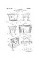
In the drawings I show in cross-section in Figs. 1 and 2, an insert placed in engageto the form. ln Figs. 3 and L I show in crosssection the insert illustrated in Figs. 1 and 2, but engaged and maintained in position by a modified form of the retaining' `means shown in Figs. 1 and 2: in Fig. 5 l show in in c.
perspective a preferred form of insert retaining means, the insert illustrated being the saine as the insert shown in Figs. 1 to 4i: Fig', 6 shows the insert retaining means illustrated in Fig. 5 as being?7 attached to a member of the form, the relation of theV insert beingoutlined by the dot and dash lines.
li/'iy invention may be embodied ina variety of simple forms and as disclosed in the present application, it is particularly adapted to retain an insert, such as I have disclosed in my Patent No. L11- 75,342 issued to me November 27, 1923. Such an insert comprises a hollow metallic structure, preferably a casting having a flanged base 10, converging side walls 11 and converging end walls l2 whereby it becomes locked in the concrete when the latter is once set. Formed interiorly of the casting are intermediate ribs 13 properly spaced to support the head of a bolt with the shank thereof extending' through the open side of the in.- sert. Adjacent the open side of the insert, l also provide similarly formed ribs lll-for engaging the head of a bolt provided with a shorter shank. It will be noted from the drawings that both sets of ribs do not extend the full length of the insert but terminate short of the end walls to permit the head of the bolt to be passed into the insert and over the ribs, the sets of ribs being' formed in staggered relation, whereby a bolt may be positioned in any desired location within the confines of the four walls of the insert.
Various expedient methods have been resorted to, to position inserts of this and other types upon the concrete form, by the use of nails, for instance, which were driven into the form in juxtaposition to therouter surfaces of the walls of the insert; also by providing` apertured lugs or holes in flanges threugh vwhich nails could pass into thev form. These methods have been effective in maintaining the insert in the desired position while the concrete is being placed in the form, but it frequently occurs that the concrete chips or cracks when the members comprising the insert fastening means are being removed and particularly when protruding nail ends are being` severed after the form has been removed.
invention contemplates the provision of a simple retaining device which may extend into the interior ofthe insert and engage the walls thereof and which may be readily attached to the concrete form separately of any attaching of the insert to the form. As shown in Figs. 1 and 2, a very simple form of my invention may comprise a strip of metal having an intermediate looped portion 16 formed to engage the side walls 11 of the insert, the ends 17 of this strip being perforated whereby the strip may be nailed to the form and the insert subsequently placed in engagement therewith. In this form of retaining means the loop portion 16 of course extends into the insert at the end to which the ribs lll do not extend.
In Figs. 3 and 4 I show the retaining means as comprising Isimply a staple member 20 with the ends 21 thereof kdriven, into the form B. In this instance the retaining means is completely covered by the insert when the latter is placed in. engagement therewith and the insert may rest, around the entire perimeter thereof, adjacent the open side, in contact with the form B.
In Figs. 5 and 6, I show a preferred form of my invention which comprises a bent metal strip formed to engage the end walls 12 of the insert and to extend therein a substantial distance whereby the .side edges ofv the strip may engage the ribs 13 and 1li and exert a stabilizing influence upon the insert once the latter is placed in engagement therewith. In this form as in the first form the ends of the metal strip are provided-with perforations 22 and 23 whereby the strip may be nailed to the form B when not in 'engagement with the insert, as shown in Fig. 6.
I find that the particular shape of the retaining strap Y illustrated in Fig. 6 involves only a minimum production cost, serves very well in engagingand maintaining the insert when once positioned thereon. This retaining member may be provided with a. sub-loop 24 which affords suiiicient spring to the end portions 25 to permit manufacturing of the strip of Va relatively inexpensive steel having low resilient qualities. is shown in Fig. 5, one leg of the member may be wider than the other whereby this leg may engage the edges of the side walls 11 of the insert and also engage the under surface of the lugs 13. The other leg and spring loop portion 24 may be of a Width corresponding to the Space between the bolt head retaining ribs whereby the horizontal lsurfaces of both sets of ribs may be engaged thereby. The'leg portions, of course, may be formed to engage a considerable surface of the tapering end walls 12, the looped portion 24 serving to permit its legs to be drawn slightly toward each other when-the open edge of the insert is being passed thereover and thereafter to cause the legs to spring apart and into firm engagement with the insert end walls.
This particular form of my invention will retain the insert when once positioned thereon during any vibration of the form incident to the construction of concrete form buildings and is quite effective in preventing any displacement of the insert when the concrete is being placed inthe form.
From the foregoing description of my invention it will be seen that while extremely simple in character from a lmanufacturing view point, its use nevertheless permits an accurate locating of the inserts and also a ready removal of the forms without necessitating the expenditure of further labor in trimming projecting nail points, etc.
, Furthermore it will be understood that my invention is adaptable to the retention of inserts of a type other than I herein disclose.
I claim- 1. In combination, a concrete form and resilient means secured to the form and adapted to engage an insert and to maintain it in position whereby concrete may be placed in the form about the insert and said means and the form eventually removed from the said concrete and insert without marring the concrete.
2. In combination, a concrete form and resilient means adapted to be attached to the form independently of an insert and over which the insert may be placed whereby the concrete formr may be removed carrying the insert positioning means with it.
3. In a concrete form the combination of a metallic strip formed to extend into the interior of a hollow insert and snugly enwalls thereof, said strip having the ends thereof adapted to be secured to a member of the form, with the intermediate portions contractible whereby the insert may be slipped over the strip and be retained theret. In combination a concrete form and resilient means secured to the form and adapted to engage the inner surfaces of the walls of a hollow insert and adapted to maintain it in position whereby concrete may be placed in the form about the insert and said means and form eventually removed from the said 'concret-e and insert without marring the concrete.
5. In combination a concrete form, and a resilient metal strip adapted to engage a hollow insert and to be secured to the form at a position at which it is desired to locate the insert and formed to engage the insert to maintain it in proper position when the concrete is being placed in the form.
6. In combination a concrete form, and a resilient metallic strip formed to engage a hollow insert and to be attached to the form separately of the insert and to engage the walls of they insert whereby it may be subsequently attached.
7. In a concrete form the combination of traotible whereby the strip is unattaohed to a. substantially hollow insert, a metallic strip concrete When set in the form and detachl formed to extend into the interior of the inably Connected to the insert. sert and snugly engage Walls thereof7 said ln testimony whereof, I hereunto affix my 5 strip having the ends thereof adapted to be signature.
permanently secured to a member of the v form with the intermediate portions oon- JOSEPH HIRSHSTEIN. n
Priority Applications (1)
| Application Number | Priority Date | Filing Date | Title |
|---|---|---|---|
| US730589A US1574483A (en) | 1924-08-07 | 1924-08-07 | Insert and holder for concrete forms |
Applications Claiming Priority (1)
| Application Number | Priority Date | Filing Date | Title |
|---|---|---|---|
| US730589A US1574483A (en) | 1924-08-07 | 1924-08-07 | Insert and holder for concrete forms |
Publications (1)
| Publication Number | Publication Date |
|---|---|
| US1574483A true US1574483A (en) | 1926-02-23 |
Family
ID=24935946
Family Applications (1)
| Application Number | Title | Priority Date | Filing Date |
|---|---|---|---|
| US730589A Expired - Lifetime US1574483A (en) | 1924-08-07 | 1924-08-07 | Insert and holder for concrete forms |
Country Status (1)
| Country | Link |
|---|---|
| US (1) | US1574483A (en) |
Cited By (2)
| Publication number | Priority date | Publication date | Assignee | Title |
|---|---|---|---|---|
| US2991532A (en) * | 1959-12-01 | 1961-07-11 | Samuel J Stiles | Chamfer strip for concrete forms |
| US5778625A (en) * | 1995-10-13 | 1998-07-14 | Bega/Us, Inc. | Recessed lighting fixture and method of installing |
-
1924
- 1924-08-07 US US730589A patent/US1574483A/en not_active Expired - Lifetime
Cited By (2)
| Publication number | Priority date | Publication date | Assignee | Title |
|---|---|---|---|---|
| US2991532A (en) * | 1959-12-01 | 1961-07-11 | Samuel J Stiles | Chamfer strip for concrete forms |
| US5778625A (en) * | 1995-10-13 | 1998-07-14 | Bega/Us, Inc. | Recessed lighting fixture and method of installing |
Similar Documents
| Publication | Publication Date | Title |
|---|---|---|
| US1794684A (en) | Anchor for veneered concrete structures | |
| US3960356A (en) | Anchor bolt holder | |
| US4308961A (en) | Article supporting structure | |
| US2020062A (en) | Structural building device | |
| US4056904A (en) | Wallboard application method and apparatus therefor | |
| US1922479A (en) | Adjustable concrete insert | |
| US2214388A (en) | Improved tie strap | |
| US2236082A (en) | Building construction | |
| US2476506A (en) | Combination fastening device | |
| US1850961A (en) | Retaining means for building materials | |
| US1574483A (en) | Insert and holder for concrete forms | |
| US1785790A (en) | Combination joist hanger and tie | |
| US1785791A (en) | Combination joist hanger and tie | |
| US2275127A (en) | Clip and molding assembly | |
| US1212843A (en) | Guide-bar support for concrete-gages. | |
| US1629848A (en) | Attaching means for building trims | |
| US1708696A (en) | Concrete construction | |
| US2819861A (en) | Support bracket for walers in concrete forms | |
| US1658407A (en) | Nailing block for composite walls | |
| US2003635A (en) | Beam hanger | |
| US1335042A (en) | Fastener for insulating-brackets | |
| US2035389A (en) | Wallboard structure and fastener | |
| US1622697A (en) | Floor clip | |
| US1187918A (en) | Fastening device for plaster-board and the like. | |
| US2094849A (en) | T head shore hanger |