US1574476A - Lifting jack - Google Patents
Lifting jack Download PDFInfo
- Publication number
- US1574476A US1574476A US47421A US4742125A US1574476A US 1574476 A US1574476 A US 1574476A US 47421 A US47421 A US 47421A US 4742125 A US4742125 A US 4742125A US 1574476 A US1574476 A US 1574476A
- Authority
- US
- United States
- Prior art keywords
- ram
- shaft
- gear
- pinion
- lowering
- Prior art date
- Legal status (The legal status is an assumption and is not a legal conclusion. Google has not performed a legal analysis and makes no representation as to the accuracy of the status listed.)
- Expired - Lifetime
Links
- 230000001276 controlling effect Effects 0.000 description 30
- 230000007246 mechanism Effects 0.000 description 21
- 230000000979 retarding effect Effects 0.000 description 9
- 238000010276 construction Methods 0.000 description 3
- 238000005192 partition Methods 0.000 description 3
- 230000001105 regulatory effect Effects 0.000 description 2
- 241000287181 Sturnus vulgaris Species 0.000 description 1
- 230000000994 depressogenic effect Effects 0.000 description 1
- 230000003455 independent Effects 0.000 description 1
- 238000004519 manufacturing process Methods 0.000 description 1
- 230000008520 organization Effects 0.000 description 1
- 230000000284 resting effect Effects 0.000 description 1
- 230000000717 retained effect Effects 0.000 description 1
- 229940113046 sorine Drugs 0.000 description 1
- ZBMZVLHSJCTVON-UHFFFAOYSA-N sotalol Chemical compound CC(C)NCC(O)C1=CC=C(NS(C)(=O)=O)C=C1 ZBMZVLHSJCTVON-UHFFFAOYSA-N 0.000 description 1
Images

Classifications
-
- B—PERFORMING OPERATIONS; TRANSPORTING
- B66—HOISTING; LIFTING; HAULING
- B66F—HOISTING, LIFTING, HAULING OR PUSHING, NOT OTHERWISE PROVIDED FOR, e.g. DEVICES WHICH APPLY A LIFTING OR PUSHING FORCE DIRECTLY TO THE SURFACE OF A LOAD
- B66F3/00—Devices, e.g. jacks, adapted for uninterrupted lifting of loads
- B66F3/08—Devices, e.g. jacks, adapted for uninterrupted lifting of loads screw operated
- B66F3/16—Devices, e.g. jacks, adapted for uninterrupted lifting of loads screw operated actuated through bevel-wheel gearings
Definitions
- This invention relates to high speed selflowering lifting jacks and has for its object the production of a jack of this character in which the speed of lowering may be regu lated either manually or automatically.
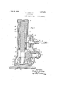
- Figure 1 represents a vertical section of a lifting jack, embodying the principles of the present invention.
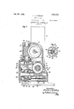
- Figure 2 represents a vertical section of same on line 2, 2 on Fig. 1.
- Figure 3 represents a section on line 3 3 on Fig. 2.
- Figure 4 represents a vertical section of the lifting jack on line 4, 4 on Fig. 2.
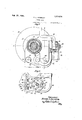
- Figure 5 represents a horizontal section of same on line 5, 5 on Fig. 1
- I Figure 6 represents a horizontal section of a portion of the lifting jack on line 6, 6 on Fig. 4.
- 10 is the base of a lifting jack having an upwardly extending projection 11, to which is threaded the lower end of a standard 12, in the upper end of which is a cylindrical bearing 13 for the vertically movable ram 14-.
- This ram 14 has an enlarged head 15 adapted to rest upon the upper end of the standard 12 when in its lowest position.
- the lower end of the ram 14 has mount-ed therein a nut 16 threaded to the main lift mg screw 17, the lower end of which has keyed thereto a bevel gear 18 meshing With bevel gear 19 formed upon the actuating shaft 20.
- the shaft 20 has mounted on its outer end a device 21 for imparting rotary movement to the shaft 20 in one direction only, and that is, during the lifting operation.
- This actuating device 21 may be of any well known construction and therefore is r not shown or described in detail.
- the standard 12 has a lateral extension 1
- the pitch of the thread of said worm 25 is such as to permit it to be rotated by said worm gear 24 in whichever direction the gear 24 may be rotated
- Surrounding the hub of the gear 18 is a hearing plate '27 having a groove in its under face into which extend the antifrictional members 28 resting upon another bearing plate 29 supported and centrally disposed upon the projection 11 of the base 10.
- One end of the worm shaft 26 is mounted in a hearing in the wall of the extension 22, while the opposite end is mounted in a hearing in a removable disk 30,threaded to the opposite wall of said extension.
- Thrust bearings 31 and 32 are provided at the opposite ends of the worm shaft 26.
- annular mem her 33 Keyed to the shaft 26 is an annular mem her 33 having loosely mounted thereon a worm gear 34 provided with an annular flange having secured therein a ratchet 36.
- the member 33 has a flange 37 at one end thereof on which is pivotally mounted a plurality of pawls 38, normally forced outwardly by springs 39 into engagement with the teeth of the ratchet 86.
- the worm gear 34 coacts with a vertical worm 39* formed upon theshaft 40.
- This shaft 40 has a bearing 41 in the lower wall of the extension 22 and another bearing 42 in the partition or wall 43 near the upper end of said extension.
- a thrust bearing Between the under face of the extension 43 and the shoulder 44 on the worm 39* is a thrust bearing
- the upper end of the shaft 40 has keyed thereto a disk 46 having pivotally mounted thereon at 47 a plurality of bearing plates 48, normally forced outwardly by springs 49, against the brake arms 50 surrounding the disk 46 and bearing plates 48, said brake arms 50 being pivoted at one end at 51 to the wall 43.
- the opposite ends of the brake arms 50 are provided with parallel, separated eX- tensions 52, between which is positioned a am member 58 mounted upon a pin 54 e2;- tending upwardly through the cover plate 55 and having an actuating finger 56 secured to its upper end.
- the partition or wall 48 has extending upwardly therefrom lugs 57 between which and the extensions 52 are disposed helical springs 58 which normally retain the brake arms 50 in contact with the bearing plates 48 pivotally mounted upon the disk 46 When the parts are in the position indicated in the drawings there will be sufficient friction between the brake arms 50 and the bearing plates 48 to retain the ram in elevated position and preventits lowering under the load.
- the extension 22 is formed integral with the two part standard 12 and the partition or wall 43 is also formed integral with the lower part thereof, this wall being somewhat depressed and forming a chamber 5.) in which the speed controlling devices 46, 48, 50 and 53 are positioned, this chamber being closed by means of the cover plate
- the bearing 23 is provided with a bushing 60 and the shaft 20 may be installed in the bearing 23 from the inner end there of before the bushing 60 is inserted into the outer end thereof, the said shaft being inserted into the chamber within the extension 22 through the opening in the bottom of the standard 12 before said standard has been threaded to the base 10.
- the bushing is then positioned within the bearing 23 and around the shaft 20 and then the actuating device 21 is installed on the outer end of said shaft.
- the worm gear 24 and the worm 25 rotate both when the ram is being raised and also when it is being lowered.
- the vertical shaft 40 extends upwardly through the disk 46 and has keyed thereto a pinion 61 normally meshing with a gear 62 on a.
- vertical shaft 63 revoluble in bearings 64 in the lateral extension 22. Adjacent these bearings 64 are anti-frictiou members 65, between which upon the shaft 63 is a worm 66.
- This worm'66 meshes with a worm gear 67 keyed to and revoluble with a shaft 68 extending through a bearing 69 in one wall of the extension 22.
- This shaft 68 has a. reduced portion 7 to which is pivoted at 71 a crank 72. Mounted on the crank 72 and slidable over the pivotal connection 71 between the reduced portion of the shaft 68 and the crank 72 is a sleeve 7 3.
- the sleeve 7 3 is in the position indicated in Fig. 1 of the drawings.
- the sleeve 73 is moved into position indicated in Fig. 5 of the drawings and the crank 72 is moved about its pivot 71 into the position indicated in said figure. In this position it is out of the operators way when he is manipulating the device 21 toraise the load.
- crank 7 2 By means of this crank 7 2 the lowering of the load may be controlled manually, as it can move downwardly no faster than the operator rotates the gear 67 by means of said crank 7 2.
- cup-shaped member 7% having a knurled head 75 by which it may be rotated about the axis of the shaft 40.
- This cup-shaped member 74f has a pin 7 6 extending laterally therefrom as indicated in Fig. 4: of the drawings.
- the high speed lowering jack may be controlled during the lowering movement, either automatically or manually at the will of the operator, the only requirement being the manipulation of the cup-shaped member 7a to bring the pinion 61 and gear 62 into mesh or permit said pinion to be moved out of mesh.
- I claim- 1 In a self-lowering lifting jack; a standard; a ram movable relatively thereto; actuating means for raising the ram; automatic means for controlling the lowering of the ram including a revoluble shaft; a pinion keyed to and slidable lengthwise of said shaft; a gear adapted to mesh with said pinion,- manually operated means for retarding the rotation of said gear; and means for moving said pinion out of mesh with said gear.
- a self-lowering lifting jack a standard; a ram movable relatively thereto; actuating means for raising the ram; automatic means for controlling the lowering of the ram including a revoluble shaft; a pinion keyed to and slidable lengthwise of saidv shaft; a gear adapted to mesh with said pinion; manually operated means for retarding the rotation of said gear; a spring to force said pinion out of mesh with said gear; and means on the end of said shaft for compressing said spring and retaining said pinion and gear in mesh.
- a self-lowering lifting jack a standard; a ram movable relatively thereto; actuating means for raising the ram; automatic means for controlling the lowering of the ram including a revoluble shaft; a pinion keyed to and slidable lengthwise of said shaft; a gear adapted to meshwith said pinion; manually operated means for retarding the rotation of said gear; a member surrounding the upper end of said shaft and adapted to compress said spring and retain said pinion and gear in mesh; and means for locking said member to prevent end movement thereof.
- a self-lowering lifting jack a standard; a ram movable relatively thereto; actuating means for raising the ram; au tomatic means for controlling the lowering of the ram including a revoluble shaft; a pinion keyed to and slidable lengthwise of said shaft; a gear adapted to mesh with said pinion; manually operated means for retarding the rotation of said gear; a spring to force said pinion out of mesh with said gear; a member surrounding the upper end of said shaft and adapted to compress said spring and retain said pinion and gear in mesh, said member being rotatable and having a bearing in the wall of the jack casing, said bearing iaving a slot extending lengthwise thereof; and a pin for locking said member to prevent end movement thereof extending laterally from said member, said pin coacting with the said wall when the spring is compressed and being positioned in said slot when the. spring is expanded.
- a self-lowering lifting jack a standard; a ram movable relatively thereto; actuating means for raising the'ram; automatic means for controlling the lowering of the ram including a revoluble shaft; a brake disk secured to and revoluble with said shaft and having in its upper face an annular recess surrounding said shaft; a pinion keyed to and slidable lengthwise of said shaft; a spring in said recess and bearing against the under face of said pinion; a gear adapted to mesh with said pinion; manually operated means for retarding the rotation of said gear; and means for cornpressing said spring and retaining said pinion and gear in mesh.
- a self-lowering lifting jack a standard; a ram movable relatively thereto; actuating means for raising the ram; automatic means for controlling the lowering of the ram including a revoluble shaft rotatable in one. direction only; a pinion keyed to and slidable lengthwise of said shaft; a gear adapted to mesh with saidpinion; manually operated means for retarding the rotation of said gear; means for moving said pinion out of mesh with said gear; and brake mechanism for controlling the rotation of said shaft when the gen 1 and pinion are'out of mesh.
- a self-lowering lifting jack a standard; a ram movable relatively thereto; actuating means for raising); the ram; automatic means for controlling the lowering of the rain including a revoluble shaft rotatable in one direction only; a. pinion keyed to and slidable lengthwise of 7 shaft; a gear adapted to mesh with pinion; manually operated means for re tarding the rotation of said gear; a spring to force said pinion out of mesh with slid gear; means on the end of said shaft for compressing said spring and retaining; said pinion and gear in mesh; and brake mechanism for controlling th rotation of said shaft when the gear and pinion are out of mesh.
- a self-lowering lifting jack a standard; a ram movable relatively thereto; actuating means f 1' raising the ram; automatic means for controlling the lowering of the rain including a revoluble shaft rotatable in one direction only; a pinion keyed to and slidable lengthwise of said shaft; a gear adapted to mesh with said pinion; manually operated means for retarding the rotation of said gear; a 'sorine' to force said pinion out of mesh with said gear: a member sur rounding the upper end of said shaft and adapted to compress said spring and retain said pinion and gear in mesh; means for locking said member to prevent end movement thereof when the spring is compressed; and brake mechanism for controlling the rotation of said shaft when the gear and pinion are out of mesh.
- fl-SQlf-lOWGIiDQ lifting jack a standard; a ram movable relatively thereto; actuating-,1 means for raising the ram; automatic means for controlling the lowering of the ram including; a revoluble shaft rotatable in one direction only; a pinion keyed to and slidable lengthwise of said shaft; a gear adapted to mesh with said pinion; manually operated means for retarding the rotation of said gear; a spring); to force said pinion out of mesh with said gear; neans adapted to compress said spring and retain said pinion and gear in mesh; brake disk rotatable with said shaft; brake arms adapted to frictionally contact with the periphery thereof; and means for controlling said frictional contact.
- actuating means for raising the ram automatic means for controlling the lowering of the ram including a revoluble shaft rotatable in one direction only; a brake disk secured to and revoluble with said shaft; brake mechanism under the control of the operator for frictionally engaging said disk and controlling its rotation; and a manually actuated crank iechanism geared to said shaft adapted to control its rotation independent of said brake mechanism.
- a self-lowering lifting jack a standard; a vertically movable ram therein; means for raising the ram; a shaft adapted to be rotated only duringthe lowering of the ram; a pinion rotatable with said shaft: a gear mes ring with and adapted to drive said pinion; a worm revoluble with said gear and alined therewith; a worm gear meshing; with and driven by said we 'm; and manually actuated means for controlling the rotation of said worm gear.
- a self-lowering lifting jack a standard; vertically movable ram therein; means for raising the ram; a shaft parallel with said ram and adapted to be rotated thereby only during the lowering); of the ram; a pinion mounted upon and rotatable with said shaft; a gear meshing with said pinion; a worm alined with said near and rotatable therewith; a worm gear meshing 'ith said worm; and a crank for rotating said worm gear.
- a self-lowering lifting jack a standard; a vertically movable ram therein; means for raising the ram; a shaft independent of said raising means and adapted to be rotated during; the lowering of the ram; a pinion mounted upon and rotatable with said shaft; a gear meshing with said pinion; a worm alined with. said rear and rotatable therewith, said worm being; parallel with said ram; a worm gear meshing with said worm; and a crank for rotating said worm 15.
- a self-lowering lifting ack a standard; a vertically movable ram therein; means for raising the ram; a shaft adapted to be rotated in one direction only, during the lowering of the ram; a pinion keyed to and rotatable with said shaft; a gear meshing and adapted to rotate said pinion; a worm secured to and revoluble with said gear; a worm gear meshing with said worm; manually actuated means for controlling the rotation of said gear; and independent brake mechanism for controlling the rotation of said shaft.
- a self-lowering lifting jack a standard; a vertically movable ram therein; means for raising the ram; a shaft independent of the raising means and parallel with said ram adapted to be rotated in one direction only, during the lowering of the ram; a pinion rotatable with said shaft; a gear meshing with said pinion; a worm revoluble with said gear; a worm gear meshing with said worm; a crank mounted on the end of the worm gear shaft and adapted to positively rotate said shaft; and independent brake mechanism for controlling the rotation of said shaft.
- a self-lowering lifting ack a standard; a vertically movable ram therein; means for raising the ram; a shaft independent of the raising means and parallel with said ram adapted to be rotated in one direction only, during the lowering of the ram; a pinion rotatable with said shaft; a gear meshing with said pinion; a worm revoluble with said gear; aworm gear meshing with said worm; manually actuated means for controlling the rotation of the worm gear; a disk on said shaft; and cam-controlled brake arms normally in frictional engage ment therewith.
- a self-lowering lifting jack a standard; a vertically movable ram therein; means for raising the ram; a shaft adapted to be rotated in one direction only during the lowering of the ram; a pinion rotatable with said shaft; a gear meshing with said pinion; a worm revoluble with said gear; a worm gear meshing with said worm; crank mechanism for controlling the rotation of the worm gear; means for moving said pinion out of mesh with said gear; a disk on said shaft and rotatable therewith; and means coacting therewith for retarding its rotation.
- a self-lowering lifting jack a standard; a vertically movable ram therein; means for raising the ram; a shaft adapted to be rotated in one direction only during the lowering of the ram; a pinion rotatable with said shaft; a gear meshing with said pinion; a worm revoluble with said gear; a worm gear meshing with said worm; manually actuated means for controlling the rotation of said worm gear; a disk rotatable with said shaft; spring actuated brake members pivotally mounted upon said disk; brake arms surrounding said disk and normally in frictional engagement with said members; means for separating said arms; and means for moving said pinion out of mesh with said gear.
- a self-lowering lifting jack a standard; a vertically movable ram supported thereby; means in the'base of said standard for raising the ram; mechanism independent of and separated from said raising means for controlling the lowering of the ram under a load; other mechanism independent of the raising means and disconnected therefrom for positively lowering the ram; and means whereby either of said mechanisms may be placed in commission. 7 :22.
- a self-lowering lifting jack In a self-lowering lifting jack, a standard; a vertically movable ram supported thereby; means in the base of said standard for raising the ram; mechanism independent of and separated from said raising means for controlling the lowering of the ram and including in part a shaft adapted to be rotated in one direction only, during the lowering of the ram; mechanism independ ent of the raising means and disconnected therefrom for positively lowering the ram; and means recipr'ocable on said shaft for connecting and disconnecting therewith the mechanism for positively lowering the ram.
- a self-lowering lifting jack a standard; a vertically movable ram supported thereby; means for raising the ram; mechanism independent'of and separated from said raising means for controlling the lowering of the ram and including in parta shaft adapted to be rotated in one direction only during the lowering of the ram; means for positively lowering the ram; and slidable means keyed to said shaft for connecting and disconnecting therewith the mechanism for positively lowering the ram.
- a self-lowering lifting jack a standard; a vertically movable ram supported thereby; means for raising the ram; mechanism independent of and separated from said raising means for controlling the lowering of the ram and including in part a shaft adapted to be rotated in one direction only during the lowering of the ram; mechanism for positively lowering the ram including a rotatable gear; a pinion slidable on said shaft; and means for. moving said pinion into and out of mesh with said gear.
Landscapes
- Life Sciences & Earth Sciences (AREA)
- Engineering & Computer Science (AREA)
- Geology (AREA)
- Mechanical Engineering (AREA)
- Structural Engineering (AREA)
- Vehicle Cleaning, Maintenance, Repair, Refitting, And Outriggers (AREA)
Description
Feb. 23 1926.
1,574,476 F. L. GORMLEY LIFTINCY JACK Filed August 1, 1.925 4 Sheets-Sheet 1 liwentor: Frank L. Gormley,
Feb. 23 1926.
F. L. GORMLEY LIFTING JACK Filed August 1 1925 4 Sheets-Sheet 3 Ewenior: I'nmkL Gormley,
m 4 m 4 h 7 s 5 .v 1 a e h S 4 m H. N Z I L w M M 1 R a. O N u O G n W ..F A.wu L I L dE e F n F Feb. 23 1926.
Inventor: Frank L. Gorm1e Jiiig.
Patented Feb. 23, 1926.
uuirun stares aruu'r ornice.
FRANK-L. GQRMLEY, O13 BRGOKLINE, MASSACHUSETTS, ASSIGNOR TO THE BUDA COMPANY, OF HARVEY, ILLINOIS, A CORPORATION OF ILLINOIS,
LIFTING JACK.
' Application filed August 1', 1925. Serial No. 47,421.
To on whom it may concern:
Be it known that I, FRANK L. GORMLEY, a citizen of the United States of America, and a resident of Brookline, in the county of Norfolk and State of Massachusetts, have invented certain new and useful Improvements in Lifting Jacks, of which the following is a specification.
This invention relates to high speed selflowering lifting jacks and has for its object the production of a jack of this character in which the speed of lowering may be regu lated either manually or automatically.
This object is attained by the mechanism illustrated in the accompanying drawings.
For the purpose of illustrating the invention, one preferred form thereof is illustrated in the drawings, this form having been found to give satisfactory and reliable results, although it is to be understood that the various instrumentalities of which the invention consists can be variously arranged and organized, and the invention-is not limited to the precise arr-agement and organization of these instrumentalities as herein shown and described except as required by the scope of the appended claims.
Of the drawings:
Figure 1 represents a vertical section of a lifting jack, embodying the principles of the present invention.
Figure 2 represents a vertical section of same on line 2, 2 on Fig. 1.
Figure 3 represents a section on line 3 3 on Fig. 2.
Figure 4 represents a vertical section of the lifting jack on line 4, 4 on Fig. 2.
Figure 5 represents a horizontal section of same on line 5, 5 on Fig. 1, and I Figure 6 represents a horizontal section of a portion of the lifting jack on line 6, 6 on Fig. 4.
Similar characters indicate like parts throughout the several figures of the draw ings.
In the drawings, 10 is the base of a lifting jack having an upwardly extending projection 11, to which is threaded the lower end of a standard 12, in the upper end of which is a cylindrical bearing 13 for the vertically movable ram 14-.
This ram 14 has an enlarged head 15 adapted to rest upon the upper end of the standard 12 when in its lowest position.
' The lower end of the ram 14 has mount-ed therein a nut 16 threaded to the main lift mg screw 17, the lower end of which has keyed thereto a bevel gear 18 meshing With bevel gear 19 formed upon the actuating shaft 20. v
The shaft 20 has mounted on its outer end a device 21 for imparting rotary movement to the shaft 20 in one direction only, and that is, during the lifting operation.
This actuating device 21 may be of any well known construction and therefore is r not shown or described in detail.
The standard 12 has a lateral extension 1 The pitch of the thread of said worm 25 is such as to permit it to be rotated by said worm gear 24 in whichever direction the gear 24 may be rotated Surrounding the hub of the gear 18 is a hearing plate '27 having a groove in its under face into which extend the antifrictional members 28 resting upon another bearing plate 29 supported and centrally disposed upon the projection 11 of the base 10.
One end of the worm shaft 26 is mounted in a hearing in the wall of the extension 22, while the opposite end is mounted in a hearing in a removable disk 30,threaded to the opposite wall of said extension.
Keyed to the shaft 26 is an annular mem her 33 having loosely mounted thereon a worm gear 34 provided with an annular flange having secured therein a ratchet 36.
The member 33 has a flange 37 at one end thereof on which is pivotally mounted a plurality of pawls 38, normally forced outwardly by springs 39 into engagement with the teeth of the ratchet 86.
The worm gear 34 coacts with a vertical worm 39* formed upon theshaft 40.
This shaft 40 has a bearing 41 in the lower wall of the extension 22 and another bearing 42 in the partition or wall 43 near the upper end of said extension.
Between the under face of the extension 43 and the shoulder 44 on the worm 39* is a thrust bearing The upper end of the shaft 40 has keyed thereto a disk 46 having pivotally mounted thereon at 47 a plurality of bearing plates 48, normally forced outwardly by springs 49, against the brake arms 50 surrounding the disk 46 and bearing plates 48, said brake arms 50 being pivoted at one end at 51 to the wall 43.
The opposite ends of the brake arms 50 are provided with parallel, separated eX- tensions 52, between which is positioned a am member 58 mounted upon a pin 54 e2;- tending upwardly through the cover plate 55 and having an actuating finger 56 secured to its upper end.
The partition or wall 48 has extending upwardly therefrom lugs 57 between which and the extensions 52 are disposed helical springs 58 which normally retain the brake arms 50 in contact with the bearing plates 48 pivotally mounted upon the disk 46 When the parts are in the position indicated in the drawings there will be sufficient friction between the brake arms 50 and the bearing plates 48 to retain the ram in elevated position and preventits lowering under the load.
When it isdesired to lower the load the operator manipulates the finger 56 causing the cam 53 to separate the brake arms 50, thereby reducing a frictional Contact between these arms and the bearing plates 48.
It is obvious that by the movement of the finger 56 about the axis of the pin 54 any degree of friction between thearms 50 and plates 48 may be secured and the speed of lowering the ram controlled.
The extension 22 is formed integral with the two part standard 12 and the partition or wall 43 is also formed integral with the lower part thereof, this wall being somewhat depressed and forming a chamber 5.) in which the speed controlling devices 46, 48, 50 and 53 are positioned, this chamber being closed by means of the cover plate The bearing 23 is provided with a bushing 60 and the shaft 20 may be installed in the bearing 23 from the inner end there of before the bushing 60 is inserted into the outer end thereof, the said shaft being inserted into the chamber within the extension 22 through the opening in the bottom of the standard 12 before said standard has been threaded to the base 10.
The bushing is then positioned within the bearing 23 and around the shaft 20 and then the actuating device 21 is installed on the outer end of said shaft.
It will be noted that in the present construction all of the gears and worms are revoluble in bearings formed in a single unitary shell, casing or standard, thereby dispensing with the cover plates generally used in lifting jacks of this character.
Heretofore, when some of the parts were mounted upon the cover plate secured to the standard or casing by means of screws, the latter would sometimes become loose and allow the cover plate to shift, thus moving out of alignment the gears for lifting the load. This movement of the gears out of alignment would cause the binding of the teeth and interfere with the proper working of the jack.
By forming all the bearings for these working parts in a single casing, this objection is wholly overcome.
The worm gear 24 and the worm 25 rotate both when the ram is being raised and also when it is being lowered.
lVhen the load is being lifted the worm 39 and worm gear 34 are prevented from being rotated by means of the braking mechanism 46, 48 and 50.
The mechanism thus far described is practically the same as that shown and described in another application of mine, filed May 15, 1925, and numbered 30,420, upon which the present application is an improvement.
The vertical shaft 40 extends upwardly through the disk 46 and has keyed thereto a pinion 61 normally meshing with a gear 62 on a. vertical shaft 63 revoluble in bearings 64 in the lateral extension 22. Adjacent these bearings 64 are anti-frictiou members 65, between which upon the shaft 63 is a worm 66.
This worm'66 meshes with a worm gear 67 keyed to and revoluble with a shaft 68 extending through a bearing 69 in one wall of the extension 22.
This shaft 68 has a. reduced portion 7 to which is pivoted at 71 a crank 72. Mounted on the crank 72 and slidable over the pivotal connection 71 between the reduced portion of the shaft 68 and the crank 72 is a sleeve 7 3.
hen it is desired to rotate the worm gear 67 by turning the crank 72, the sleeve 7 3 is in the position indicated in Fig. 1 of the drawings. When such manual rotation of the gear 67 is not desired the sleeve 73 is moved into position indicated in Fig. 5 of the drawings and the crank 72 is moved about its pivot 71 into the position indicated in said figure. In this position it is out of the operators way when he is manipulating the device 21 toraise the load.
By means of this crank 7 2 the lowering of the load may be controlled manually, as it can move downwardly no faster than the operator rotates the gear 67 by means of said crank 7 2.
Above the pinion 61 and surrounding the upper end of the shaft is a cup-shaped member 7% having a knurled head 75 by which it may be rotated about the axis of the shaft 40. This cup-shaped member 74f has a pin 7 6 extending laterally therefrom as indicated in Fig. 4: of the drawings.
\Vhen the pinion til-and gear 62 are in mesh, the pin 7 6 is retained against the lower face of the wall 77 by means of a spring 78 positioned in an annular recess in the disk 46.
When it is desired to control the lowering of the load automatically the operator turns the cupshaped member 74 until the pin 76 is in register with the slot 79 in the wall 77.
When this pin 7 6 is brought into register with the slot 79 the spring 78 will force the pinion 61 and cup-shaped member 74 upwardly until said pinion is out of mesh with its coact-ing gear 62.
lVhen in this position it is obvious that the speed of lowering must be governed automatically, as the connection with the manually controlling device has been disconnected. In this case the speed is regulated by manipulating the finger 56 controlling the. position of the brake arms 50.
By means of this simple construction, the high speed lowering jack may be controlled during the lowering movement, either automatically or manually at the will of the operator, the only requirement being the manipulation of the cup-shaped member 7a to bring the pinion 61 and gear 62 into mesh or permit said pinion to be moved out of mesh.
It is believed that the operation and many advantages of the invention will be understood without further description.
Having thus described my invention, I claim- 1. In a self-lowering lifting jack; a standard; a ram movable relatively thereto; actuating means for raising the ram; automatic means for controlling the lowering of the ram including a revoluble shaft; a pinion keyed to and slidable lengthwise of said shaft; a gear adapted to mesh with said pinion,- manually operated means for retarding the rotation of said gear; and means for moving said pinion out of mesh with said gear.
2. In a self-lowering lifting jack; a standard; a ram movable relatively thereto; actuating means for raising the ram; automatic means for controlling the lowering of the ram including a revoluble shaft; a pinion keyed to and slidable lengthwise of saidv shaft; a gear adapted to mesh with said pinion; manually operated means for retarding the rotation of said gear; a spring to force said pinion out of mesh with said gear; and means on the end of said shaft for compressing said spring and retaining said pinion and gear in mesh.
3. In a self-lowering lifting jack; a standard; a ram movable relatively thereto; actuating means for raising the ram; automatic means for controlling the lowering of the ram including a revoluble shaft; a pinion keyed to and slidable lengthwise of said shaft; a gear adapted to meshwith said pinion; manually operated means for retarding the rotation of said gear; a member surrounding the upper end of said shaft and adapted to compress said spring and retain said pinion and gear in mesh; and means for locking said member to prevent end movement thereof.
l. In a self-lowering lifting jack; a standard; a ram movable relatively thereto; actuating means for raising the ram; au tomatic means for controlling the lowering of the ram including a revoluble shaft; a pinion keyed to and slidable lengthwise of said shaft; a gear adapted to mesh with said pinion; manually operated means for retarding the rotation of said gear; a spring to force said pinion out of mesh with said gear; a member surrounding the upper end of said shaft and adapted to compress said spring and retain said pinion and gear in mesh, said member being rotatable and having a bearing in the wall of the jack casing, said bearing iaving a slot extending lengthwise thereof; and a pin for locking said member to prevent end movement thereof extending laterally from said member, said pin coacting with the said wall when the spring is compressed and being positioned in said slot when the. spring is expanded.
5. In a self-lowering lifting jack; a standard; a ram movable relatively thereto; actuating means for raising the'ram; automatic means for controlling the lowering of the ram including a revoluble shaft; a brake disk secured to and revoluble with said shaft and having in its upper face an annular recess surrounding said shaft; a pinion keyed to and slidable lengthwise of said shaft; a spring in said recess and bearing against the under face of said pinion; a gear adapted to mesh with said pinion; manually operated means for retarding the rotation of said gear; and means for cornpressing said spring and retaining said pinion and gear in mesh.
6. In a self-lowering lifting jack; a standard; a ram movable relatively thereto; actuating means for raising the ram; automatic means for controlling the lowering of the ram including a revoluble shaft rotatable in one. direction only; a pinion keyed to and slidable lengthwise of said shaft; a gear adapted to mesh with saidpinion; manually operated means for retarding the rotation of said gear; means for moving said pinion out of mesh with said gear; and brake mechanism for controlling the rotation of said shaft when the gen 1 and pinion are'out of mesh.
7. In a self-lowering lifting jack; a standard; a ram movable relatively thereto; actuating means for raising); the ram; automatic means for controlling the lowering of the rain including a revoluble shaft rotatable in one direction only; a. pinion keyed to and slidable lengthwise of 7 shaft; a gear adapted to mesh with pinion; manually operated means for re tarding the rotation of said gear; a spring to force said pinion out of mesh with slid gear; means on the end of said shaft for compressing said spring and retaining; said pinion and gear in mesh; and brake mechanism for controlling th rotation of said shaft when the gear and pinion are out of mesh. I
8. In a self-lowering lifting jack; a standard; a ram movable relatively thereto; actuating means f 1' raising the ram; automatic means for controlling the lowering of the rain including a revoluble shaft rotatable in one direction only; a pinion keyed to and slidable lengthwise of said shaft; a gear adapted to mesh with said pinion; manually operated means for retarding the rotation of said gear; a 'sorine' to force said pinion out of mesh with said gear: a member sur rounding the upper end of said shaft and adapted to compress said spring and retain said pinion and gear in mesh; means for locking said member to prevent end movement thereof when the spring is compressed; and brake mechanism for controlling the rotation of said shaft when the gear and pinion are out of mesh.
9. In fl-SQlf-lOWGIiDQ lifting jack, a standard; a ram movable relatively thereto; actuating-,1 means for raising the ram; automatic means for controlling the lowering of the ram including; a revoluble shaft rotatable in one direction only; a pinion keyed to and slidable lengthwise of said shaft; a gear adapted to mesh with said pinion; manually operated means for retarding the rotation of said gear; a spring); to force said pinion out of mesh with said gear; neans adapted to compress said spring and retain said pinion and gear in mesh; brake disk rotatable with said shaft; brake arms adapted to frictionally contact with the periphery thereof; and means for controlling said frictional contact.
lOuln a self-lowering lifting; jack; a standard; a ram movable relatively thereof;
actuating means for raising the ram; automatic means for controlling the lowering of the ram including a revoluble shaft rotatable in one direction only; a brake disk secured to and revoluble with said shaft; brake mechanism under the control of the operator for frictionally engaging said disk and controlling its rotation; and a manually actuated crank iechanism geared to said shaft adapted to control its rotation independent of said brake mechanism.
11. In a self-lowering lifting jack; a standard; a vertically movable ram therein; means for raising the ram; a shaft adapted to be rotated only duringthe lowering of the ram; a pinion rotatable with said shaft: a gear mes ring with and adapted to drive said pinion; a worm revoluble with said gear and alined therewith; a worm gear meshing; with and driven by said we 'm; and manually actuated means for controlling the rotation of said worm gear.
12. In a self-lowering;- lifting jacL; a standard; a vertically movable ram therein; means for raising' the rar shaft adapted to be rotated only during the lowering of the ram; a pinion rotatable with said shaft; a gear meshing with and adapted to drive said pinion-z a worm revoluble with said gear and alined therewith; a worm gear meshing; with and adapted to drive said worm; and a crank mounted on the end of the worm gear shaft.
13. In a self-lowering lifting jack; a standard; vertically movable ram therein; means for raising the ram; a shaft parallel with said ram and adapted to be rotated thereby only during the lowering); of the ram; a pinion mounted upon and rotatable with said shaft; a gear meshing with said pinion; a worm alined with said near and rotatable therewith; a worm gear meshing 'ith said worm; and a crank for rotating said worm gear.
14. In a self-lowering lifting jack; a standard; a vertically movable ram therein; means for raising the ram; a shaft independent of said raising means and adapted to be rotated during; the lowering of the ram; a pinion mounted upon and rotatable with said shaft; a gear meshing with said pinion; a worm alined with. said rear and rotatable therewith, said worm being; parallel with said ram; a worm gear meshing with said worm; and a crank for rotating said worm 15. In a self-lowering;- lifting jacx; a standard; a vertically movable ram therein; means for raising the ram; a shaft adapted to be rotated during; the lowering of the r m; a pinion rotatable with said shaft; a gear meshing with said pinion; a worm revoluble with said ear; a worm gear 1neshing with said worm; manually actuated means for controlling the rotation of said worm gear; a disk upon said shaft; brake arms surrounding said disk and normally in frictional engagement therewith; means for separating said arms; and means for moving said pinion out of mesh with said gear.
16. In a self-lowering lifting ack; a standard; a vertically movable ram therein; means for raising the ram; a shaft adapted to be rotated in one direction only, during the lowering of the ram; a pinion keyed to and rotatable with said shaft; a gear meshing and adapted to rotate said pinion; a worm secured to and revoluble with said gear; a worm gear meshing with said worm; manually actuated means for controlling the rotation of said gear; and independent brake mechanism for controlling the rotation of said shaft.
17. In a self-lowering lifting jack; a standard; a vertically movable ram therein; means for raising the ram; a shaft independent of the raising means and parallel with said ram adapted to be rotated in one direction only, during the lowering of the ram; a pinion rotatable with said shaft; a gear meshing with said pinion; a worm revoluble with said gear; a worm gear meshing with said worm; a crank mounted on the end of the worm gear shaft and adapted to positively rotate said shaft; and independent brake mechanism for controlling the rotation of said shaft.
18. In a self-lowering lifting ack; a standard; a vertically movable ram therein; means for raising the ram; a shaft independent of the raising means and parallel with said ram adapted to be rotated in one direction only, during the lowering of the ram; a pinion rotatable with said shaft; a gear meshing with said pinion; a worm revoluble with said gear; aworm gear meshing with said worm; manually actuated means for controlling the rotation of the worm gear; a disk on said shaft; and cam-controlled brake arms normally in frictional engage ment therewith.
19. In a self-lowering lifting jack; a standard; a vertically movable ram therein; means for raising the ram; a shaft adapted to be rotated in one direction only during the lowering of the ram; a pinion rotatable with said shaft; a gear meshing with said pinion; a worm revoluble with said gear; a worm gear meshing with said worm; crank mechanism for controlling the rotation of the worm gear; means for moving said pinion out of mesh with said gear; a disk on said shaft and rotatable therewith; and means coacting therewith for retarding its rotation.
20. In a self-lowering lifting jack; a standard; a vertically movable ram therein; means for raising the ram; a shaft adapted to be rotated in one direction only during the lowering of the ram; a pinion rotatable with said shaft; a gear meshing with said pinion; a worm revoluble with said gear; a worm gear meshing with said worm; manually actuated means for controlling the rotation of said worm gear; a disk rotatable with said shaft; spring actuated brake members pivotally mounted upon said disk; brake arms surrounding said disk and normally in frictional engagement with said members; means for separating said arms; and means for moving said pinion out of mesh with said gear.
21. In a self-lowering lifting jack, a standard; a vertically movable ram supported thereby; means in the'base of said standard for raising the ram; mechanism independent of and separated from said raising means for controlling the lowering of the ram under a load; other mechanism independent of the raising means and disconnected therefrom for positively lowering the ram; and means whereby either of said mechanisms may be placed in commission. 7 :22. In a self-lowering lifting jack, a standard; a vertically movable ram supported thereby; means in the base of said standard for raising the ram; mechanism independent of and separated from said raising means for controlling the lowering of the ram and including in part a shaft adapted to be rotated in one direction only, during the lowering of the ram; mechanism independ ent of the raising means and disconnected therefrom for positively lowering the ram; and means recipr'ocable on said shaft for connecting and disconnecting therewith the mechanism for positively lowering the ram.
23. In a self-lowering lifting jack, a standard; a vertically movable ram supported thereby; means for raising the ram; mechanism independent'of and separated from said raising means for controlling the lowering of the ram and including in parta shaft adapted to be rotated in one direction only during the lowering of the ram; means for positively lowering the ram; and slidable means keyed to said shaft for connecting and disconnecting therewith the mechanism for positively lowering the ram.
24. In a self-lowering lifting jack, a standard; a vertically movable ram supported thereby; means for raising the ram; mechanism independent of and separated from said raising means for controlling the lowering of the ram and including in part a shaft adapted to be rotated in one direction only during the lowering of the ram; mechanism for positively lowering the ram including a rotatable gear; a pinion slidable on said shaft; and means for. moving said pinion into and out of mesh with said gear.
Signed by me at Boston, Mass. this 6th day of July, 1925. I
- FRANK L. GORMLEY.
Priority Applications (1)
| Application Number | Priority Date | Filing Date | Title |
|---|---|---|---|
| US47421A US1574476A (en) | 1925-08-01 | 1925-08-01 | Lifting jack |
Applications Claiming Priority (1)
| Application Number | Priority Date | Filing Date | Title |
|---|---|---|---|
| US47421A US1574476A (en) | 1925-08-01 | 1925-08-01 | Lifting jack |
Publications (1)
| Publication Number | Publication Date |
|---|---|
| US1574476A true US1574476A (en) | 1926-02-23 |
Family
ID=21948868
Family Applications (1)
| Application Number | Title | Priority Date | Filing Date |
|---|---|---|---|
| US47421A Expired - Lifetime US1574476A (en) | 1925-08-01 | 1925-08-01 | Lifting jack |
Country Status (1)
| Country | Link |
|---|---|
| US (1) | US1574476A (en) |
-
1925
- 1925-08-01 US US47421A patent/US1574476A/en not_active Expired - Lifetime
Similar Documents
| Publication | Publication Date | Title |
|---|---|---|
| US1680515A (en) | Ratchet mechanism for lifting jacks | |
| US2233798A (en) | Brake controlling means for hoists | |
| US2391172A (en) | Hoisting mechanism | |
| US1574476A (en) | Lifting jack | |
| US1877171A (en) | Switch control mechanisms | |
| US1395341A (en) | Self-lowering jack | |
| US1615268A (en) | Lifting jack | |
| US1437753A (en) | Self-lowering jack | |
| US1687127A (en) | Brake mechanism for lifting jacks | |
| US1378226A (en) | Lifting-jack | |
| US1303734A (en) | smythe | |
| US1395340A (en) | Speed-retarding device for lifting-jacks | |
| US1334488A (en) | Lifting-jack | |
| US1383201A (en) | Brake mechanism for lifting-jacks and the like | |
| US1849712A (en) | Lifting jack | |
| US1352207A (en) | Lifting-jack | |
| US1324345A (en) | gormley | |
| US1131286A (en) | Lifting-jack. | |
| US1383199A (en) | Speed-controlling mechanism for load-lifting devices | |
| US1522463A (en) | Hoisting mechanism | |
| US1397871A (en) | Jack | |
| US1287966A (en) | Lifting-jack. | |
| US1706710A (en) | Self-lowering jack | |
| US1798878A (en) | Lifting jack | |
| US1396951A (en) | Lifting-jack |