US1574441A - Tape condenser - Google Patents
Tape condenser Download PDFInfo
- Publication number
- US1574441A US1574441A US56183A US5618325A US1574441A US 1574441 A US1574441 A US 1574441A US 56183 A US56183 A US 56183A US 5618325 A US5618325 A US 5618325A US 1574441 A US1574441 A US 1574441A
- Authority
- US
- United States
- Prior art keywords
- aprons
- pulley
- speed
- condenser
- winding drums
- Prior art date
- Legal status (The legal status is an assumption and is not a legal conclusion. Google has not performed a legal analysis and makes no representation as to the accuracy of the status listed.)
- Expired - Lifetime
Links
- 238000004804 winding Methods 0.000 description 26
- 230000002093 peripheral effect Effects 0.000 description 7
- 238000009960 carding Methods 0.000 description 3
- 238000010276 construction Methods 0.000 description 3
- 241000533363 Apion Species 0.000 description 1
- 241000973252 Diagramma Species 0.000 description 1
- 239000011324 bead Substances 0.000 description 1
- 230000008602 contraction Effects 0.000 description 1
- 230000000694 effects Effects 0.000 description 1
- 210000000582 semen Anatomy 0.000 description 1
Images
Classifications
-
- D—TEXTILES; PAPER
- D01—NATURAL OR MAN-MADE THREADS OR FIBRES; SPINNING
- D01G—PRELIMINARY TREATMENT OF FIBRES, e.g. FOR SPINNING
- D01G27/00—Lap- or sliver-winding devices, e.g. for products of cotton scutchers, jute cards, or worsted gill boxes
Definitions
- This invention relates to a condenser of the apron type which is employed for condensing the stock dotted from carding machines into. roving.
- the object of the invention isto provide simple and efficient means. for readily adjusting in accordance with the conditions prevailing the speed of the condensing elements, the speed of the aprons, and the peripheral speed of the Winding drums.
- the object of the invention more particularly is to provide a simple and .eflicient means for adjusting the peripheral speed of the winding drums with respect to the speed of the corresponding aprons so as to vary the tension on the rovingsfas they pass from the banks of aprons to the winding drums.
- the object of the invention is further to provide a simple and efiicient adjusting means for the latter purpose which may be operated while the condenser is in operation and consequently without stopping the machine.
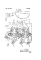
- FIG. 1 is a side elevation, chiefly in diagramma c f rm, o a :portionot a tap condenser and a arding mach e;
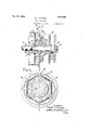
- Fig. 4 is a view in end elevation of an expansible pulley employed in a preferred embod ment o the n ent on in th h p rtio '1 of the carding cylinder, of the machine is illustrated and a portion of the driving. belt 2 extending therefrom to and driving the main pulley f the c n e s r- Qne of the side frames l of the condenser shown at th de of t e a hin whe e the main elements with which the present i vention is more particularly concerned'are located.
- the condenser is illustrated as 'pe irld d wit f u bank of wo aprons.
- the stock taken from the carding machine and divided by the usual dividing rolls is ca ried byt tapes 1 n y p r y i11u$- trated, in the usual manner to the upper aprons of the upper two banks and the lower aprons of the lower two banks.
- the strands stock areconclensed by the aprons in the usual manner and'passed therefrom in the form of rovings 1-7, 1-8, 19, 20 over the re sp chive-winding drums 12, 13, 14 ⁇ and 15and ar round pon correspon ing spind s
- the present invent-ion has to do with the driving mechanism forthe aprons and the winding drums, and as already pointed out,
- a driving, sprocket wheel 21, which is the common driving element for the several banks of aprons is ournalled at 22 in the machine frame and has rigidly connected thereto a gear 23 meshing with a gear 24 driven through a suitable train of gearing from a pinion 25 and driven by the pulley 3.
- the gear 28 is one of a set of interchangeable gears, each of which has a different number of teeth but all of which have the same pitch diameter. Consequently any one of the set of gears may be substituted for another and consequently the speed of this common driving element may be adjusted as required.
- the gears 23 are indicated as having respectively 54, 56, 58 andGO teeth.
- a sprocket chain 26 extends around the sprocket wheel 21, around suitable idlers 27 and 28 and around sprocket pinions 29, 80, 31 and 32 which respectively form part of the drive for each bank of aprons.
- the sprocket pinion 29 is journalled-at 33 and carries rigid therewith a gear 34 which is one of a set of interchangeable gears each having a different numberof teeth but all of the same pitch diameter. As indicated in Fig. 2 as an example these gears may have 46, 47 48, 49 and 50 teeth respectively.
- the apron 5 is carried by the rollers 35 and 36 and the apron 6 by the rollers 37 and 88.
- the rollers 35 and 37 have rigidly connected therewith intermeshing pinions 39 and 40 respectively and the pinion 39 int-ermeshes with the gear 34. It will thus beseen that the aprons are driven by the sprocket pinion 29 and that by substituting one or the other of the interchangeable gears 34 the speed of the aprons may be adjusted.
- the drive for the winding drums is a belt drive.
- a stub shaft 41 is keyed in the side frame at 42 and held in place by a nut 43.
- This stub shaft has journalled thereon a combined sprocket wheel 44 and pulley
- a belt 46 passes around the pulley 45 and leads around each of the winding drums 12, 13, 14 and 15 and around suitable idlers 47.
- the sprocket chain is utilized to drive this combined belt and sprocket wheel unit and for that purpose passes around the sprocket wheel 44 as shown.
- the speed of the belt 46 is adjusted as required by expanding and contracting the pulley 45.
- a simple and preferred form of construction of expansible pulley is illustrated in detail in Figs. 3 and' 4.
- the hub 48 of the sprocket wheel 44 is provided with radially extending arms 49.
- the pulley itself is divided into segments each having an inwardly projecting radial P 50 Pl eedto l de rad al y on the corresponding arm 49.
- A. guide bolt 51 passes through the slot 52 in each arm 50 and is threaded into the corresponding sprocket arm 49 and locked in place by a lock nut 53.
- the several segments of the pulley may slide on the arms 49 radially to expand Or contract the circumference of the pulley. These segments are yieldingly held contracted by helical springs 54 extending between lugs 55 of adjacent segments.
- the inner ends of the arms 50 of the pulley segments are shaped to present conical faces and these faces engage a cone 56 mounted to slide upon a portion of the hub 48 and a portion of a hub screw 57 threaded onto the end of the stub shaft 41.
- Ball thrust bearings 58 and 59 are provided between the hub 48 and a flange 60 on the stub shaft 41 and between the sliding cone 56 and a shoulder on the. hub screw 57.
- a look nut (31 is threaded onto the stub shaft to lock the hub screw 57 in its adjusted posit-ion.
- the construction of the sprocket wheel and pulley unit illustrated is such that the lock nut 61 and hub screw 57 may readily be operated when the machine is itself in operation to effect the expansion or contraction of the pulley and consequently the adjustment of the peripheral speeds of the winding drums relativelyv to the speed of the banks of aprons and this is an important feature of the invention because it enables the rovings running from the banks of aprons to the winding drums to be put under proper tension according to the observed conditions during the operation of the machine.
- the combination of the means for adjusting the belt drive 46 with the means for adjusting the common drive for the banks of aprons and the means for adjusting inclependently the drive for each bank of aprons presents a very elastic arrangement by which all adjustments of apron speed and winding drum speed may readily be effected as required.
- tape condenser comprising a plurality of banks of aprons, a winding drum for each bank of aprons, a driven pulley, a belt extending around the pulley and all of the winding drums, and means for radially expanding and contracting the pulley to adjust the speed of the belt and thereby the peripheral speed of the winding drums relatively to'the speed of the aprons.
- a tape condenser comprising a plurality of banks of aprons, a winding drum for each-reek. 9 g es a tlri ee P l extending around the pulley and all of the winding drums, and means, operable while the condenser is running, for radially expanding and contracting the pulley to ad just the speed of the belt and thereby. the peripheral speed of the Winding drums relatively to the speed of the aprons.
- a tape condenser comprising a plurality of banks of aprons, a drive, including a set of interchangeable gears of the same pitch diameter, for each bank of aprons, a common driver for all of the said drives also including a set of interchangeable gears of the same pitch diameter, a Winding drum for each bank of aprons, a driving pulley, a belt extending around the pulley and all of the Winding drums, and means for radially expanding and contracting the pulley, whereby the speed of the banks of aprons may be simultaneously or independently adjusted and whereby the peripheral speed of the winding drums relatively to the speed of the aprons may also be adjusted.
- a tape condenser comprising a plurality of banks of aprons, a winding drum for each bank of aprons, apulley, means for radially expanding and contracting the pulley, a driven sprocket Wheel having a drivwheel, a sprocket pinion drive, including a r set of interchangeable gears of the same pitch diameter, for driving each bank of aprons, a belt extending around the pulley and all of the winding drums, and a sprocket chain extending around the two sprocket Wheels and all of the sprocket pinions, whereby the speed of the condenser, the speed of the banks of aprons, and the peripheral speed of the winding drums may be adjusted as required.
- a combined sprocket wheel and pulley unit for a tape condenser in which the sprocket wheel carries a sprocket chain leading to the several apron drives, and in which the pulley carries a belt leading to the several Winding drums, and in which means are provided for radially expanding and contracting the pulley whereby the relative speeds of the belt and sprocket chain may readily be adjusted as required.
Landscapes
- Engineering & Computer Science (AREA)
- Textile Engineering (AREA)
- Spinning Or Twisting Of Yarns (AREA)
Description
Feb. 23 1926.
' w. T. PUTNAM TAPE CONDENSER Filed Sept. 2;, 1925 2 Sheets-$heet 1 lnvenTdf'. .Wu|Ter T. FuTnum Feb. 23 1926. 1,574,441 w. T. PUTNAM v TAPE CONDENSER Filed Se t. 14, 1925 2 Sheets-Sheet 2 8i i v 42 2 so a .nngm a M 14 I I v v l venr r- WalTer T p m Anya.
Patented Feb. 23, 1926.
UNITED STATES TENT 0 5F165 Tron or} massnol us'n'rrs,
W LTEB fU N m 0F 5? 03TH, ANDQVE Q MA$$A H E T$ A$SIQN9B 9 DAV S 6.
screens MACHINE COMPANY, or no vrn Anno'vnn, nssAicnusnTrs, A congen t- TABE CONDENSER.
Application filed September 14, 1825. Serial No. 56,183.
To all whom it may concern:
Be it known that I, lVAL'rnR T. PUTNAM, a citizen of the United States, and resident of North Andover, county of Essex, State of Massachusetts, have invented an Improvement in' Tape Condensers, of which the following description, in connection with the accompanying drawing, is a specification, like characters on the drawing representing like parts.
This invention relates to a condenser of the apron type which is employed for condensing the stock dotted from carding machines into. roving.
The object of the invention isto provide simple and efficient means. for readily adjusting in accordance with the conditions prevailing the speed of the condensing elements, the speed of the aprons, and the peripheral speed of the Winding drums.
The object of the invention more particularly is to provide a simple and .eflicient means for adjusting the peripheral speed of the winding drums with respect to the speed of the corresponding aprons so as to vary the tension on the rovingsfas they pass from the banks of aprons to the winding drums.
The object of the invention is further to provide a simple and efiicient adjusting means for the latter purpose which may be operated while the condenser is in operation and consequently without stopping the machine.
These and other objects and features of the invention will appear. morelfully from the accompanying description and drawings and will be particularly pointed out in the claims; i
The general type of tape container illustrated in connection with a preferred embodiment of the present invention is well known and familiar to those skilled in the art and has long been in use, Consequently it is necessary here to illustrate .anddescribe only so much of the.constructionand operation' thereof as is necessary to an understanding of the present invention.
In the adrawingsi Fig. 1 is a side elevation, chiefly in diagramma c f rm, o a :portionot a tap condenser and a arding mach e;
il 2 is 5. detail .alsoT-in [diagrammatic form illustrating the drive for one bank of apr ns Fig. 3 is a view, hiefly in cross section, aken on t e lin F g 4;
Fig. 4 is a view in end elevation of an expansible pulley employed in a preferred embod ment o the n ent on in th h p rtio '1 of the carding cylinder, of the machine is illustrated and a portion of the driving. belt 2 extending therefrom to and driving the main pulley f the c n e s r- Qne of the side frames l of the condenser shown at th de of t e a hin whe e the main elements with which the present i vention is more particularly concerned'are located. The condenser is illustrated as 'pe irld d wit f u bank of wo aprons.
a d 6. each I clined face ra kets 91111. 0 i'elo etedon he a n am at p per points t re ve an guid the spindles 11 on which the rovings are wound as they pass from the'respective banks of aprons. P A series 01" Winding drums 12 13, kl and 15' are jou rnalled in the side frame, one for each bank of aprons and in each case the rovings pass from the corresponding bank of aprons overone of these wind ing drums and onto the corresponding spindle. The mass of roving as it is wound onthe spindle rests on the winding drum.
The stock taken from the carding machine and divided by the usual dividing rolls is ca ried byt tapes 1 n y p r y i11u$- trated, in the usual manner to the upper aprons of the upper two banks and the lower aprons of the lower two banks. The strands stock areconclensed by the aprons in the usual manner and'passed therefrom in the form of rovings 1-7, 1-8, 19, 20 over the re sp chive-winding drums 12, 13, 14} and 15and ar round pon correspon ing spind s The present invent-ion has to do with the driving mechanism forthe aprons and the winding drums, and as already pointed out,
it is unnecessary fintlier to describe the constru'cbidn andoperation of the machine.
The apions'farefdriven by meansot an adjustab e dr v iore ch ba koif ap ns d acommon .diji 'ngm ch anism fora-ll of these drives w11ic11; 1tse1;: t isladjustable so that not on y men-th ed Qftheapm s bead justed semen speedref bank at aprons may be adjusted independently. In the I construction illustrated a driving, sprocket wheel 21, which is the common driving element for the several banks of aprons is ournalled at 22 in the machine frame and has rigidly connected thereto a gear 23 meshing with a gear 24 driven through a suitable train of gearing from a pinion 25 and driven by the pulley 3. The gear 28 is one of a set of interchangeable gears, each of which has a different number of teeth but all of which have the same pitch diameter. Consequently any one of the set of gears may be substituted for another and consequently the speed of this common driving element may be adjusted as required. As an illustration the gears 23 are indicated as having respectively 54, 56, 58 andGO teeth.
A sprocket chain 26 extends around the sprocket wheel 21, around suitable idlers 27 and 28 and around sprocket pinions 29, 80, 31 and 32 which respectively form part of the drive for each bank of aprons.
As the drive for each bank of aprons is the same in each case it will be suflicient to describe the one for the uppermost bank. The sprocket pinion 29 is journalled-at 33 and carries rigid therewith a gear 34 which is one of a set of interchangeable gears each having a different numberof teeth but all of the same pitch diameter. As indicated in Fig. 2 as an example these gears may have 46, 47 48, 49 and 50 teeth respectively.
The apron 5 is carried by the rollers 35 and 36 and the apron 6 by the rollers 37 and 88. The rollers 35 and 37 have rigidly connected therewith intermeshing pinions 39 and 40 respectively and the pinion 39 int-ermeshes with the gear 34. It will thus beseen that the aprons are driven by the sprocket pinion 29 and that by substituting one or the other of the interchangeable gears 34 the speed of the aprons may be adjusted.
The drive for the winding drums is a belt drive. A stub shaft 41 is keyed in the side frame at 42 and held in place by a nut 43. This stub shaft has journalled thereon a combined sprocket wheel 44 and pulley A belt 46 passes around the pulley 45 and leads around each of the winding drums 12, 13, 14 and 15 and around suitable idlers 47. The sprocket chain is utilized to drive this combined belt and sprocket wheel unit and for that purpose passes around the sprocket wheel 44 as shown. I
The speed of the belt 46 is adjusted as required by expanding and contracting the pulley 45. A simple and preferred form of construction of expansible pulley is illustrated in detail in Figs. 3 and' 4. As shown therein the hub 48 of the sprocket wheel 44 is provided with radially extending arms 49. The pulley itself is divided into segments each having an inwardly projecting radial P 50 Pl eedto l de rad al y on the corresponding arm 49. A. guide bolt 51 passes through the slot 52 in each arm 50 and is threaded into the corresponding sprocket arm 49 and locked in place by a lock nut 53.
It will thus be seen that the several segments of the pulley may slide on the arms 49 radially to expand Or contract the circumference of the pulley. These segments are yieldingly held contracted by helical springs 54 extending between lugs 55 of adjacent segments. The inner ends of the arms 50 of the pulley segments are shaped to present conical faces and these faces engage a cone 56 mounted to slide upon a portion of the hub 48 and a portion of a hub screw 57 threaded onto the end of the stub shaft 41. It will be seen, therefore, that by screwing in the hub screw 57 the cone 56 will act to slide the pulley segments outwardly and expand the pulley and that when the hub screw is screwed outwardly the springs 54 will act to contract the pulcy segments. Ball thrust bearings 58 and 59 are provided between the hub 48 and a flange 60 on the stub shaft 41 and between the sliding cone 56 and a shoulder on the. hub screw 57. A look nut (31 is threaded onto the stub shaft to lock the hub screw 57 in its adjusted posit-ion.
The construction of the sprocket wheel and pulley unit illustrated is such that the lock nut 61 and hub screw 57 may readily be operated when the machine is itself in operation to effect the expansion or contraction of the pulley and consequently the adjustment of the peripheral speeds of the winding drums relativelyv to the speed of the banks of aprons and this is an important feature of the invention because it enables the rovings running from the banks of aprons to the winding drums to be put under proper tension according to the observed conditions during the operation of the machine. I
The combination of the means for adjusting the belt drive 46 with the means for adjusting the common drive for the banks of aprons and the means for adjusting inclependently the drive for each bank of aprons presents a very elastic arrangement by which all adjustments of apron speed and winding drum speed may readily be effected as required.
I claim: 7
1. tape condenser comprising a plurality of banks of aprons, a winding drum for each bank of aprons, a driven pulley, a belt extending around the pulley and all of the winding drums, and means for radially expanding and contracting the pulley to adjust the speed of the belt and thereby the peripheral speed of the winding drums relatively to'the speed of the aprons.
2. A tape condenser comprising a plurality of banks of aprons, a winding drum for each-reek. 9 g es a tlri ee P l extending around the pulley and all of the winding drums, and means, operable while the condenser is running, for radially expanding and contracting the pulley to ad just the speed of the belt and thereby. the peripheral speed of the Winding drums relatively to the speed of the aprons.
3. A tape condenser comprising a plurality of banks of aprons, a drive, including a set of interchangeable gears of the same pitch diameter, for each bank of aprons, a common driver for all of the said drives also including a set of interchangeable gears of the same pitch diameter, a Winding drum for each bank of aprons, a driving pulley, a belt extending around the pulley and all of the Winding drums, and means for radially expanding and contracting the pulley, whereby the speed of the banks of aprons may be simultaneously or independently adjusted and whereby the peripheral speed of the winding drums relatively to the speed of the aprons may also be adjusted.
4. A tape condenser comprising a plurality of banks of aprons, a winding drum for each bank of aprons, apulley, means for radially expanding and contracting the pulley, a driven sprocket Wheel having a drivwheel, a sprocket pinion drive, including a r set of interchangeable gears of the same pitch diameter, for driving each bank of aprons, a belt extending around the pulley and all of the winding drums, and a sprocket chain extending around the two sprocket Wheels and all of the sprocket pinions, whereby the speed of the condenser, the speed of the banks of aprons, and the peripheral speed of the winding drums may be adjusted as required.
5. A combined sprocket wheel and pulley unit for a tape condenser in which the sprocket wheel carries a sprocket chain leading to the several apron drives, and in which the pulley carries a belt leading to the several Winding drums, and in which means are provided for radially expanding and contracting the pulley whereby the relative speeds of the belt and sprocket chain may readily be adjusted as required.
In testimony whereof, I have signed my name to this specification.
lVALTER- T. PUTNAM.
Priority Applications (1)
| Application Number | Priority Date | Filing Date | Title |
|---|---|---|---|
| US56183A US1574441A (en) | 1925-09-14 | 1925-09-14 | Tape condenser |
Applications Claiming Priority (1)
| Application Number | Priority Date | Filing Date | Title |
|---|---|---|---|
| US56183A US1574441A (en) | 1925-09-14 | 1925-09-14 | Tape condenser |
Publications (1)
| Publication Number | Publication Date |
|---|---|
| US1574441A true US1574441A (en) | 1926-02-23 |
Family
ID=22002718
Family Applications (1)
| Application Number | Title | Priority Date | Filing Date |
|---|---|---|---|
| US56183A Expired - Lifetime US1574441A (en) | 1925-09-14 | 1925-09-14 | Tape condenser |
Country Status (1)
| Country | Link |
|---|---|
| US (1) | US1574441A (en) |
Cited By (1)
| Publication number | Priority date | Publication date | Assignee | Title |
|---|---|---|---|---|
| US9334944B2 (en) * | 2014-08-05 | 2016-05-10 | Deere & Company | Pulley assembly for belt drive |
-
1925
- 1925-09-14 US US56183A patent/US1574441A/en not_active Expired - Lifetime
Cited By (1)
| Publication number | Priority date | Publication date | Assignee | Title |
|---|---|---|---|---|
| US9334944B2 (en) * | 2014-08-05 | 2016-05-10 | Deere & Company | Pulley assembly for belt drive |
Similar Documents
| Publication | Publication Date | Title |
|---|---|---|
| US1574441A (en) | Tape condenser | |
| US2219856A (en) | Microvariable paper machine drive | |
| DE2125597A1 (en) | Spindle drive - for spinning machines, suitable for high speeds | |
| US2059979A (en) | Web handling apparatus | |
| US1998430A (en) | Machine for making wire rope or the like | |
| US1701685A (en) | Machine for making elastic paper | |
| US1521318A (en) | Variable-speed-driving mechanism for condensers | |
| US1644374A (en) | Driving end for looms | |
| US1799896A (en) | Spinning frame and spindle-drive mechanism | |
| US2180555A (en) | Machine and method for rolling rivets | |
| US1737345A (en) | Wire-drawing machine | |
| US1649751A (en) | Driving mechanism of spinning and analogous machines | |
| US1842565A (en) | Chase adjuster for spinning frames | |
| US1416712A (en) | Calico-printing machine | |
| DE339675C (en) | Machine for grinding inner cylinder surfaces, especially on multi-cylinder housings for automobiles | |
| SU22623A1 (en) | Box Gluing Machine | |
| US1803045A (en) | Driving mechanism for paper-making machines | |
| US1498012A (en) | Slack-twisted-yarn preventive | |
| US1796392A (en) | Differential spindle-drum drive for spinning frames | |
| US617276A (en) | John boyd | |
| US1568539A (en) | Spindle-driving mechanism | |
| US2205920A (en) | Driving mechanism for wool card strippers | |
| US1505433A (en) | Means for waxing yarns | |
| US114074A (en) | Improvement in spinning-machines | |
| US2705504A (en) | Gear train arrangement in the driving mechanism of weaving looms |