US1574432A - Shock absorber - Google Patents
Shock absorber Download PDFInfo
- Publication number
- US1574432A US1574432A US695257A US69525724A US1574432A US 1574432 A US1574432 A US 1574432A US 695257 A US695257 A US 695257A US 69525724 A US69525724 A US 69525724A US 1574432 A US1574432 A US 1574432A
- Authority
- US
- United States
- Prior art keywords
- spring
- shock absorber
- lever
- bore
- slot
- Prior art date
- Legal status (The legal status is an assumption and is not a legal conclusion. Google has not performed a legal analysis and makes no representation as to the accuracy of the status listed.)
- Expired - Lifetime
Links
- 230000035939 shock Effects 0.000 title description 11
- 239000006096 absorbing agent Substances 0.000 title description 7
- 230000006835 compression Effects 0.000 description 3
- 238000007906 compression Methods 0.000 description 3
- 238000010276 construction Methods 0.000 description 2
- TVEXGJYMHHTVKP-UHFFFAOYSA-N 6-oxabicyclo[3.2.1]oct-3-en-7-one Chemical compound C1C2C(=O)OC1C=CC2 TVEXGJYMHHTVKP-UHFFFAOYSA-N 0.000 description 1
- 238000010521 absorption reaction Methods 0.000 description 1
- 230000001105 regulatory effect Effects 0.000 description 1
- 230000000284 resting effect Effects 0.000 description 1
- 238000000926 separation method Methods 0.000 description 1
- 230000000153 supplemental effect Effects 0.000 description 1
Images
Classifications
-
- B—PERFORMING OPERATIONS; TRANSPORTING
- B60—VEHICLES IN GENERAL
- B60G—VEHICLE SUSPENSION ARRANGEMENTS
- B60G11/00—Resilient suspensions characterised by arrangement, location or kind of springs
- B60G11/32—Resilient suspensions characterised by arrangement, location or kind of springs having springs of different kinds
- B60G11/34—Resilient suspensions characterised by arrangement, location or kind of springs having springs of different kinds including leaf springs
- B60G11/36—Resilient suspensions characterised by arrangement, location or kind of springs having springs of different kinds including leaf springs and also helical, spiral or coil springs
Definitions
- - reference 1 designates a housing
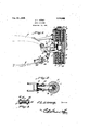
- This invention relatesto a shock absorber designed .for use in connect-ion with motor vehicles, one of the objects of the invention being to provide a simple form of device which can be applied readily to vehicles and will act as a supplemental means for absorbing the shock to which the vehicle is subjected, the said shock absorber being coupled to and actuated by the movement of the body relative to the springs used for supporting the same.
- Fig. 2 is a section on line 2-2 ⁇ r Fig. 1.
- Fig. 3 is a section on line 3-3,'Fig. 1.
- a bracket 5 1 and is adapted to be ⁇ secured to of the frame F of the vehicle.
- That portion vof the housing between the counter bore'iI is slotted asv showirat14 and the inner ends Vof the rods 11 and 13 are located back of the slot andare provided with heads Pivotally connected to.
- the frame F at the point wherethe spring S is usually connected is a ⁇ lever 16 one endof which jects loosely through the slot '14 and is vided with an opening 17 into which 13 extends loosely, from the rod being preventedby the head on said rod.
- the ⁇ lever 16 extends through pro- rod
- shock absorbers such as described can be placed between the springs and the frame at any point desired.
- the compression of the springsS and 9 can be regulated by means of nuts 26 engaging the rods ll and 13. By means'of these nuts the disks or heads 10 and 12 can be shifted against the spring to hold them under-Vincreased compression.
- a shock absorber including a housing having a longitudinal bore extending there through, the ends of the bore being counter bored to provide interior shoulders, there being a longitudinal guide slot in the housing between the counter bores and opening .into the central portion of the bore, disks normally resting upon the shoulders at the inner ends of the counter bores, rods slidably mounted within the respective disks, head connected to the respective rods and slidable Within the respective counter bores, a'spring Within each counter bore bearing at one end against the disk therein and at its other rend against the head therein, crossed pivotally connected levers projecting at one end through the slot and into the bore, said levers engaging and adapted to actuate the respective rods, a bracket for tixedly attaching the housing to a vehicle, and means for movably connectinfr the outer ends of the levers to a vehicle frame and spring respectively.
Landscapes
- Engineering & Computer Science (AREA)
- Mechanical Engineering (AREA)
- Vibration Dampers (AREA)
- Vibration Prevention Devices (AREA)
Description
- reference 1 designates a housing, 45
Patented Feb. 23, 1926. l
. l 'i 1,574,432; UNITED Stars-s rarsarorrica.
JOHN IES'LLB. LVZEY, OF MDDLETOW'N, OHIO..
SHOCK ABsoRBnR;
' Application filed February ze, 1924. serial no.- 535,257.,
To all wlw/mf t may concern.'
VBe it known that I, JOHN L. Livznr, a citizen of the United States, residing at Middletown, in the county of Butler and State of Ohio, have invented anew and useful Shock Absorber, of which vthe following is a specification. 1
This invention relatesto a shock absorber designed .for use in connect-ion with motor vehicles, one of the objects of the invention being to provide a simple form of device which can be applied readily to vehicles and will act as a supplemental means for absorbing the shock to which the vehicle is subjected, the said shock absorber being coupled to and actuated by the movement of the body relative to the springs used for supporting the same.
Another object is to provide a device of this character which is simple'and comp-act in construction' and will not readily get out of order. n
lVith the foregoing and other objects in view which will appear as the description proceeds, the invention resides in the combination and arrangement. of parts and in the n details of construction hereinafter described and claimed, it. being understood that within the scope of what is claimed without departing from the spirit of the invention.
In the accompanying drawings the preferred form of the invention has been shown.
tions being shown by broken lines.
Fig. 2 is a section on line 2-2`r Fig. 1. Fig. 3 is a section on line 3-3,'Fig. 1. Referring to the figures by characters of preferably cylindrical, the same being provided with counter bores 2 and 3 in the upper and lower ends thereof, the upper counter bore being preferably closed normally by a screw cap 4. A bracket 5 1 and is adapted to be` secured to of the frame F of the vehicle. t
The inner end of eachcounter bore 2 and 3 provides a seat 6 and these seats are'engaged by disks 7 one of which constitutes a aV portion disk constitutes a bearing for a coiled spring changes in the precise embodiment of the invention herein disclosed may be made is attached tothe housing caring for a coiled spring 8 while the other` 9. ySpring 8 bears upwardly against a head 10V connected to one end of a rod 11 movable 'loosely within the disk 7. Spring 9 bears against a head 12 secured to a rodv 13 movable loosely inthe other disk 7. That portion vof the housing between the counter bore'iI is slotted asv showirat14 and the inner ends Vof the rods 11 and 13 are located back of the slot andare provided with heads Pivotally connected to. the frame F at the point wherethe spring S is usually connected, is a `lever 16 one endof which jects loosely through the slot '14 and is vided with an opening 17 into which 13 extends loosely, from the rod being preventedby the head on said rod. The` lever 16 extends through pro- rod
Vthe downwardlyV extended forked portion.
18 of a'lever v19, the two levers being pivotally connected at 20.
1liand has an opening 21-intowhich the rod 11 projects loosely, the head of said rod preventing separation of the lever from the ro'd. The lower end portion of lever 18 has itsy sides slotted as shown at 22. The eye a at the end of the spring S is located between the slottedportions of the lever 19 anda bolt 23 extends through this eye and through the slot 20. Rollersf24rl bolt kbetween eye 0;. and the ends of the bolt and are adapted to work within the vslots 22.V Heads 25 on the ends of the bolts serve to prevent the rollers frombecoming displaced laterally relative to the slots'and also la the sides of the lever to holdV the .lever against'spreading. Y Y
As shown in Fig. 1 the shock absorber is frame moves downwardly relative to the spring the two levers 16 and 19 swing relative to each other about the pivot 20 soy that those ends thereof within they housing 1 will be moved toward each other. This will result inz compression of the springs 8 and. 9 and consequent absorption of shock. Dur ing this relative movement of the frame and spring the rollers 24 will travel within the slots22 as will be apparent. Furthermore the levers will be guided by the walls of the slot`14 so as to be held in prop-er positions relative to each other and thus prevent distortionV of the pivotV 20.
It will be noted that this structure does n TheV upper end ,of lever 19 is extended loosely through the slot Vseparation ofthe leverVV Y i adapted Vto be used as a connection between the frame F and the spring S. When the not interfere with the function ofthe spring S but merely serves as asupplemental means for absorbing shocks ,that would not be taken care 0f by the spring S.
Obviously shock absorbers such as described can be placed between the springs and the frame at any point desired. The compression of the springsS and 9 can be regulated by means of nuts 26 engaging the rods ll and 13. By means'of these nuts the disks or heads 10 and 12 can be shifted against the spring to hold them under-Vincreased compression.
Ythat vis claimed is A shock absorber including a housing having a longitudinal bore extending there through, the ends of the bore being counter bored to provide interior shoulders, there being a longitudinal guide slot in the housing between the counter bores and opening .into the central portion of the bore, disks normally resting upon the shoulders at the inner ends of the counter bores, rods slidably mounted within the respective disks, head connected to the respective rods and slidable Within the respective counter bores, a'spring Within each counter bore bearing at one end against the disk therein and at its other rend against the head therein, crossed pivotally connected levers projecting at one end through the slot and into the bore, said levers engaging and adapted to actuate the respective rods, a bracket for tixedly attaching the housing to a vehicle, and means for movably connectinfr the outer ends of the levers to a vehicle frame and spring respectively.
In testimony that claim the foregoing as my own, I have hereto afiixed my signature.
JOHN LESTER LIVZEY.
Priority Applications (1)
| Application Number | Priority Date | Filing Date | Title |
|---|---|---|---|
| US695257A US1574432A (en) | 1924-02-26 | 1924-02-26 | Shock absorber |
Applications Claiming Priority (1)
| Application Number | Priority Date | Filing Date | Title |
|---|---|---|---|
| US695257A US1574432A (en) | 1924-02-26 | 1924-02-26 | Shock absorber |
Publications (1)
| Publication Number | Publication Date |
|---|---|
| US1574432A true US1574432A (en) | 1926-02-23 |
Family
ID=24792273
Family Applications (1)
| Application Number | Title | Priority Date | Filing Date |
|---|---|---|---|
| US695257A Expired - Lifetime US1574432A (en) | 1924-02-26 | 1924-02-26 | Shock absorber |
Country Status (1)
| Country | Link |
|---|---|
| US (1) | US1574432A (en) |
-
1924
- 1924-02-26 US US695257A patent/US1574432A/en not_active Expired - Lifetime
Similar Documents
| Publication | Publication Date | Title |
|---|---|---|
| US1605798A (en) | Marcel charles van cbombb | |
| US2512269A (en) | Hydraulic shock absorber | |
| US1574432A (en) | Shock absorber | |
| US2581619A (en) | Vehicle wheel chock | |
| US1799894A (en) | Automobile bumper | |
| US1294467A (en) | Shock-absorber. | |
| US1526169A (en) | Spring damper for vehicles | |
| US1679268A (en) | Shock absorber | |
| US1501382A (en) | Shock absorber | |
| US1733430A (en) | Crutch | |
| US1500138A (en) | Shock absorber | |
| US1535921A (en) | Shock absorber | |
| US1775082A (en) | Adjustable automobile seat | |
| US1319783A (en) | Compressed-air shock-absorber | |
| US1419838A (en) | Shock absorber | |
| US1771276A (en) | Vehicle shock absorber or doorcheck | |
| US1422163A (en) | Door check | |
| US1316500A (en) | Shock-absorber | |
| US1567929A (en) | Shock absorber | |
| US1178862A (en) | Shock-absorber. | |
| US1872460A (en) | Shock absorber | |
| US2653811A (en) | Shock stabilizer for vehicle axles | |
| US1254106A (en) | Shock-absorber. | |
| US1595787A (en) | Cover for oiling devices | |
| US1419614A (en) | Shock absorber |