US1574422A - Dust collector or filter - Google Patents
Dust collector or filter Download PDFInfo
- Publication number
- US1574422A US1574422A US537858A US53785822A US1574422A US 1574422 A US1574422 A US 1574422A US 537858 A US537858 A US 537858A US 53785822 A US53785822 A US 53785822A US 1574422 A US1574422 A US 1574422A
- Authority
- US
- United States
- Prior art keywords
- bag
- filter
- conductor
- dust collector
- dust
- Prior art date
- Legal status (The legal status is an assumption and is not a legal conclusion. Google has not performed a legal analysis and makes no representation as to the accuracy of the status listed.)
- Expired - Lifetime
Links
- 239000000428 dust Substances 0.000 title description 22
- 239000004020 conductor Substances 0.000 description 29
- 230000005611 electricity Effects 0.000 description 13
- 230000003068 static effect Effects 0.000 description 11
- 239000004744 fabric Substances 0.000 description 10
- 238000007599 discharging Methods 0.000 description 8
- 238000004880 explosion Methods 0.000 description 4
- 238000009825 accumulation Methods 0.000 description 2
- 238000004519 manufacturing process Methods 0.000 description 2
- 208000004998 Abdominal Pain Diseases 0.000 description 1
- 208000002881 Colic Diseases 0.000 description 1
- 241000282941 Rangifer tarandus Species 0.000 description 1
- 230000015572 biosynthetic process Effects 0.000 description 1
- 238000004140 cleaning Methods 0.000 description 1
- 238000010276 construction Methods 0.000 description 1
- 238000010892 electric spark Methods 0.000 description 1
- 238000009434 installation Methods 0.000 description 1
- 239000002184 metal Substances 0.000 description 1
- 230000004048 modification Effects 0.000 description 1
- 238000012986 modification Methods 0.000 description 1
- 230000000737 periodic effect Effects 0.000 description 1
Images
Classifications
-
- B—PERFORMING OPERATIONS; TRANSPORTING
- B01—PHYSICAL OR CHEMICAL PROCESSES OR APPARATUS IN GENERAL
- B01D—SEPARATION
- B01D46/00—Filters or filtering processes specially modified for separating dispersed particles from gases or vapours
- B01D46/02—Particle separators, e.g. dust precipitators, having hollow filters made of flexible material
- B01D46/04—Cleaning filters
-
- B—PERFORMING OPERATIONS; TRANSPORTING
- B01—PHYSICAL OR CHEMICAL PROCESSES OR APPARATUS IN GENERAL
- B01D—SEPARATION
- B01D46/00—Filters or filtering processes specially modified for separating dispersed particles from gases or vapours
- B01D46/0027—Filters or filtering processes specially modified for separating dispersed particles from gases or vapours with additional separating or treating functions
- B01D46/0032—Filters or filtering processes specially modified for separating dispersed particles from gases or vapours with additional separating or treating functions using electrostatic forces to remove particles, e.g. electret filters
-
- B—PERFORMING OPERATIONS; TRANSPORTING
- B01—PHYSICAL OR CHEMICAL PROCESSES OR APPARATUS IN GENERAL
- B01D—SEPARATION
- B01D46/00—Filters or filtering processes specially modified for separating dispersed particles from gases or vapours
- B01D46/66—Regeneration of the filtering material or filter elements inside the filter
- B01D46/74—Regeneration of the filtering material or filter elements inside the filter by forces created by movement of the filter element
- B01D46/76—Regeneration of the filtering material or filter elements inside the filter by forces created by movement of the filter element involving vibrations
Definitions
- ROBERT F. FEIND a citizen of the United States, residing at West Allis, in the county of Milwaukee and State of Wisconsin, has invented a certain new and useful Im rovement in Dust Collectors .or Filters, 0 which the following is a specification.
- This invention relates to the removal of static charges. from filter elements, and is particularly applicable to fabric filters such as are used in dust collectors.
- Dust collecting apparatus usually comprises a filter element through which the dust-laden 'air is ll blown or drawn.- In such apparatus, fires and explosions sometimes occur particularly when the dust is inflammable.
- One of the objects of the invention is to prevent the occurrence of such fires and explosions. It
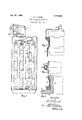
- Fig. 1 is an elevation of a dust collecting apparatus in which the invention has been applied, a portion thereof being shown in section.
- Fig. 2 is a fragmentary detail view of the upper portion of one of the, dust collecting or filter elements a part thereof being in longitudinal section, and
- Fig. 3 is a similar view of the lower por- 45 tion of one of said elements.
- Fig. 4 is a fragmentary detail view of a longitudinal section of a portion .of one of the filter' elements;
- substantially cylindricalbaglike elements of fabric which, for the sake of brevity, will be hereinafter referred to as bags.
- the lower ends of the bags are disposed around tubular extensions surrounding openings in a bottom plate 6, as will hereinafter more particularly appear.
- the upper ends of the bags are disposed around blocks 778, 9, 10, respectively.
- the blocks are respectively supported by rods 11 in turn supported by a cross rod12.
- the cross rod 12 is supported by a connecting rod 13 and through thelatter associated with a shaking-mechanism 14.
- This shaking mechanism may be such a one as disclosed in the patent to R. C. Newhouse, No.
- the bag4 is shown in detail in Figs. 2 3 and 4.
- the lower end of the bag is turned inwardl around a ring of rope 15 and may be suita ly stitched'in this position.
- This end of the bag may be disposed about a tubular extension 16 of the bottom plate 6.
- Between the extension 16 and the bag 4 is an elementof shellacked fabric 17.
- the bag may be suitably fastened to the extension 16 as by a fabric belt 21.
- the upper end of the bag is shown in Fig. 2 as similarly provided with a rope ring and this end .is disposed around block 9and may be fastened thereto by a fabric bel
- a bare electrical conductor" 18 is disposed on the outer surface of the bag 4 and is. here shown as running along said surface the full len th of the bag.
- Ba s 2 and 3 are here shown as being provided with bare electrical conductors 26 respectively disposed on the outer surface of the bag in the same manner as conductor 18 with respect to bag 4 except that conductors 26 are wound helically around the respective bags. In certain instances where it may be desirable to secure a better contact the conductor may be wound in this helical fashion. It is however to be undertsood that all of the bags may be provided with straight longitudinal conductors or all of them may be provided with helically wound conductors. Furthermore if desired, each bag may be provided with more than one conductor like conduc tor 18 for example, disposed at different lines on the circumference of the individual ags.
- each bag has been grounded by reason of the electrical conductor associated therewith.
- grounded it is to be understood the connection of the electrical conductor to what amounts toa large reservoir for electricity which may be the metal frame of a machine or the earth itself, or both.
- static electricity accumulating on the bag or tending to accumulatethere may be conducted away or discharged so as to prevent an accumulation of electricity at high potential, or to discharge it in such manner that sparks from said discharge will not cause fires or explosions.
- a dust collector of the bag type having a filter bag provided with means for discharging static charges of electricity on said filter comprising a grounded electrical conductor in contact with a substantial portion of said ba 2.
- a dust colic-tor of the bag type having a filter bag provided with means for discharging static charges of electricity on said filter comprising a grounded electrical conductor in contact with said bag substantially throughout the length of said bag.
- a dust collector of the bag type having a filter bag provided with means for discharging static charges of electricity on said filter comprising a ounded electrical conlductor in contact with the outside of said 4.
- a dust collector of the bag type having a filter bag provided with means for discharging static charges of electricity on said filter comprising a grounded bare electrical conductor in contact with a substantial portion of the outside of said bag.
- a dust collector of the bag type having a filter bag provided with means for dis charging static charges of electricity on said filter comprising a grounded electrical conductor in contact with the outside of said bag substantially throughout the length of said ba 6.
- a dust collector of the bag type having a filter bag provided with-means for discharging statlc charges of electricity on said filter comprising a. grounded bare electrical conductor in contact with the outside of said bag substantially throughout the length of said bag.
- a dust collector of the bag type having a filter bag provided with means for discharging static charges of electricity on said filter comprising a grounded electrical conductor wound helically around said bag.
- a dust collector of the bag type having a filter bag provided with means for discharging static charges of electricity on said filter comprising a grounded bare electrical conductor wound helically around said bag.
- a fabric. filter adapted to be used in a dust collector, said filter having a bare electrical conductor permanently fastened thereto and associated with a substantial portion of an outer surface of said filter so that static electricity may be removed therefrom.
- a three dimensional dust collector provided with filter means having a portion salielectricity on said surface including at least one grounded electrical conductor in contact with a substantial portion of said surface. 10
Landscapes
- Chemical & Material Sciences (AREA)
- Chemical Kinetics & Catalysis (AREA)
- Elimination Of Static Electricity (AREA)
- Filtering Of Dispersed Particles In Gases (AREA)
Description
Feb. 23 1926. 7' 1,574,422
R. F. FEIND DUST COLLECTOR OR FILTER Filed Feb. 20 1922 I Patented F eb. 23, 1926.
UNITED STATES iPA'fENT OFFIE'.
ROBERT F. FEIND, OF WEST ALLIS, WISCONSIN, ASSIGNOR TO ALLIS-CHALEIERS MAN- UFACTURING COMPANY, OF MILWAUKEE, WISCONSIN, A GQBPORATION F DELA- WARE.
nvs'r coLLEcron' on rrarnn.
Application filed February 20, 1922. Serial no. 537,858.
To all whom it may concern! Be it known that ROBERT F. FEIND, a citizen of the United States, residing at West Allis, in the county of Milwaukee and State of Wisconsin, has invented a certain new and useful Im rovement in Dust Collectors .or Filters, 0 which the following is a specification.
This invention relates to the removal of static charges. from filter elements, and is particularly applicable to fabric filters such as are used in dust collectors. Dust collecting apparatus usually comprises a filter element through which the dust-laden 'air is ll blown or drawn.- In such apparatus, fires and explosions sometimes occur particularly when the dust is inflammable. One of the objects of the invention is to prevent the occurrence of such fires and explosions. It
has been found that filter elements in dust collectorsbecome char ed with static electricity'and it is thereore a more specific object to discharge ofprevent the accumulation or formation of such charges to the end 26 that electric sparks will not cause. fires and explosions. Other objects will appear as the description of the invention proceeds.
The novel features of the invention will more particularly appear from the specification and the accompanying drawing forming a part thereof and showing one embodiment of said invention, and all thesenovel features are intended to be pointed out in the claims.
.In the drawings:
Fig. 1 is an elevation of a dust collecting apparatus in which the invention has been applied, a portion thereof being shown in section.
Fig. 2 is a fragmentary detail view of the upper portion of one of the, dust collecting or filter elements a part thereof being in longitudinal section, and
Fig. 3 is a similar view of the lower por- 45 tion of one of said elements.
Fig. 4 is a fragmentary detail view of a longitudinal section of a portion .of one of the filter' elements; v
Referring now more .particularly to Fig.
comprises an outer casing 1 in which are disposed the filter elements proper 2, 3, 4, 5,
here shown as substantially cylindricalbaglike elements of fabric, which, for the sake of brevity, will be hereinafter referred to as bags. The lower ends of the bags are disposed around tubular extensions surrounding openings in a bottom plate 6, as will hereinafter more particularly appear. The upper ends of the bags are disposed around blocks 778, 9, 10, respectively. The blocks are respectively supported by rods 11 in turn supported by a cross rod12. ,The cross rod 12 is supported by a connecting rod 13 and through thelatter associated with a shaking-mechanism 14. This shaking mechanism may be such a one as disclosed in the patent to R. C. Newhouse, No.
1,168,543, Jan. 18, 1916, assigned to Allis- Chalmers Manufacturing Company. This shaking mechanism is so designed that the bags are normally in the slack position, that is, when dust-la en airv is being introduced. *lIliJQ the inside of the bags. is further such that during an interval in The operation which the-flow of air through the bags is reversed, the bags are suddenly stretched and released, thereby cleaning the same.
The bag4 is shown in detail in Figs. 2 3 and 4. The lower end of the bag is turned inwardl around a ring of rope 15 and may be suita ly stitched'in this position. This end of the bag may be disposed about a tubular extension 16 of the bottom plate 6. Between the extension 16 and the bag 4 is an elementof shellacked fabric 17. The bag may be suitably fastened to the extension 16 as by a fabric belt 21. The upper end of the bag is shown in Fig. 2 as similarly provided with a rope ring and this end .is disposed around block 9and may be fastened thereto by a fabric bel A bare electrical conductor" 18 is disposed on the outer surface of the bag 4 and is. here shown as running along said surface the full len th of the bag. The conductor 18 may be astened to the bag in any suitable manner. In view of the periodic stretching and =re-slackening of the bag, the conductor is.
preferably of the stranded type so as to rentier it flexible. 50 1, the dust collecting apparatus here shown v At the lowerv end of the bag conductor 18 15 shown in electrical contact with the bottom plate 6. suitable means such as it screw 19. may be used for holding the conductor to the bottom plate. At the upper end, the conductor 18 is in electrical contact with the rod 11 where it may be held as by means of a clamp 20. The conductor 18 is preferably sewed to the bag before the installation of the latter in the dust collcting apparatus, and the fabric belts for holding the bag to the block and tubular extension respectively will pass over the conductor as shown in Figs. 2 .and 3. Elsewhere, however, the conductor 18 is entirely bare.
Referring again to Fig. 1, the bag 4 is shown as provided with a plurality of rings 22, 23, 24, 26 for holding the shape of the bag. As will be seen from Fig. 4, showing a section of ring 22, these rings are disposed inside of the bag and are held in position by folding the fabric toward the inner periphery of the ring and suitably stitching the fabric together at the point of contact. The section of Fig. 4 is taken near the wire 18 and therefore shows the manner in which the latter passes over the ring and the fabric of the bag covering the same. It is not essential that the conductor 18 be in contact with the bag to a point as near the ring 22 as indicated in Fig. 4 but it may leave the surface of the bag and jump over the ring with a less abrupt turn than as shown at the point 27.
What has been stated in connection with bag 4 also applies to bag 5.
Ba s 2 and 3 are here shown as being provided with bare electrical conductors 26 respectively disposed on the outer surface of the bag in the same manner as conductor 18 with respect to bag 4 except that conductors 26 are wound helically around the respective bags. In certain instances where it may be desirable to secure a better contact the conductor may be wound in this helical fashion. It is however to be undertsood that all of the bags may be provided with straight longitudinal conductors or all of them may be provided with helically wound conductors. Furthermore if desired, each bag may be provided with more than one conductor like conduc tor 18 for example, disposed at different lines on the circumference of the individual ags.
From the above, it will be apparent that each bag has been grounded by reason of the electrical conductor associated therewith. By the term grounded it is to be understood the connection of the electrical conductor to what amounts toa large reservoir for electricity which may be the metal frame of a machine or the earth itself, or both. The essential thing is merely that static electricity accumulating on the bag or tending to accumulatethere may be conducted away or discharged so as to prevent an accumulation of electricity at high potential, or to discharge it in such manner that sparks from said discharge will not cause fires or explosions.
It will of course be understood that the invention may be applied in dust filters or collectors of other form than the one herein described by way of example. It is not desired that the invention claimed be limited to the exact details of construction shown and described as obvious modifications will occur to a person skilled in the art.
It is claimed and desired to secure by Letters Patent:
1. A dust collector of the bag type, having a filter bag provided with means for discharging static charges of electricity on said filter comprising a grounded electrical conductor in contact with a substantial portion of said ba 2. A dust colic-tor of the bag type, having a filter bag provided with means for discharging static charges of electricity on said filter comprising a grounded electrical conductor in contact with said bag substantially throughout the length of said bag.
3. A dust collector of the bag type, having a filter bag provided with means for discharging static charges of electricity on said filter comprising a ounded electrical conlductor in contact with the outside of said 4. A dust collector of the bag type, having a filter bag provided with means for discharging static charges of electricity on said filter comprising a grounded bare electrical conductor in contact with a substantial portion of the outside of said bag.
5. A dust collector of the bag type, having a filter bag provided with means for dis charging static charges of electricity on said filter comprising a grounded electrical conductor in contact with the outside of said bag substantially throughout the length of said ba 6. A dust collector of the bag type, having a filter bag provided with-means for discharging statlc charges of electricity on said filter comprising a. grounded bare electrical conductor in contact with the outside of said bag substantially throughout the length of said bag.
7. A dust collector of the bag type having a filter bag provided with means for discharging static charges of electricity on said filter comprising a grounded electrical conductor wound helically around said bag.
8. A dust collector of the bag type having a filter bag provided with means for discharging static charges of electricity on said filter comprising a grounded bare electrical conductor wound helically around said bag.
9. As an article of manufacture, a fabric. filter adapted to be used in a dust collector, said filter having a bare electrical conductor permanently fastened thereto and associated with a substantial portion of an outer surface of said filter so that static electricity may be removed therefrom.
10. A three dimensional dust collector provided with filter means having a portion salielectricity on said surface including at least one grounded electrical conductor in contact with a substantial portion of said surface. 10
v In testimony whereof, the signature of the inventor is afiixed hereto.
ROBERT F. FEIND.
Priority Applications (1)
| Application Number | Priority Date | Filing Date | Title |
|---|---|---|---|
| US537858A US1574422A (en) | 1922-02-20 | 1922-02-20 | Dust collector or filter |
Applications Claiming Priority (1)
| Application Number | Priority Date | Filing Date | Title |
|---|---|---|---|
| US537858A US1574422A (en) | 1922-02-20 | 1922-02-20 | Dust collector or filter |
Publications (1)
| Publication Number | Publication Date |
|---|---|
| US1574422A true US1574422A (en) | 1926-02-23 |
Family
ID=24144401
Family Applications (1)
| Application Number | Title | Priority Date | Filing Date |
|---|---|---|---|
| US537858A Expired - Lifetime US1574422A (en) | 1922-02-20 | 1922-02-20 | Dust collector or filter |
Country Status (1)
| Country | Link |
|---|---|
| US (1) | US1574422A (en) |
Cited By (12)
| Publication number | Priority date | Publication date | Assignee | Title |
|---|---|---|---|---|
| US2667941A (en) * | 1951-02-24 | 1954-02-02 | Jr Regner A Ekstrom | Unitary heat exchange and particle collecting apparatus for combustion gases |
| US2684126A (en) * | 1951-06-19 | 1954-07-20 | Doyle Vacuum Cleaner Co | Dust collector for vacuum cleaners, blowers, and other dust filters |
| US2804937A (en) * | 1953-10-21 | 1957-09-03 | Goodyear Tire & Rubber | Air filter with orderly arranged filaments |
| US3545178A (en) * | 1967-07-06 | 1970-12-08 | Buell Eng Co | Bag type separator apparatus having cleaning means therefor |
| US3766712A (en) * | 1971-12-14 | 1973-10-23 | American Air Filter Co | Fabric tube type dust collector method |
| US3937621A (en) * | 1974-11-25 | 1976-02-10 | Phillips Petroleum Company | Filter bag cuff |
| US4133656A (en) * | 1976-03-23 | 1979-01-09 | Becton, Dickinson And Company | Bacteria filters with transparent housings |
| DE2830540A1 (en) * | 1978-07-12 | 1980-01-31 | Heinz Hoelter | Dust filter element material - mfd. by coating mineral fibres with conductive metal |
| US4335589A (en) * | 1980-06-30 | 1982-06-22 | Bentley-Harris Manufacturing Co. | Grounding structures comprising composite knitted fabrics |
| US7438736B1 (en) * | 2007-06-21 | 2008-10-21 | General Electric Company | Filter bag structure |
| US20150151235A1 (en) * | 2010-10-14 | 2015-06-04 | Air Dynamics Industrial Systems Corporation | Filter Chambers and Self-Cleaning Apparatus for Vacuum Systems |
| RU233748U1 (en) * | 2024-12-24 | 2025-05-05 | Федеральное государственное бюджетное образовательное учреждение высшего образования "Волгоградский государственный технический университет" (ВолгГТУ) | SLEEVE FILTER |
-
1922
- 1922-02-20 US US537858A patent/US1574422A/en not_active Expired - Lifetime
Cited By (15)
| Publication number | Priority date | Publication date | Assignee | Title |
|---|---|---|---|---|
| US2667941A (en) * | 1951-02-24 | 1954-02-02 | Jr Regner A Ekstrom | Unitary heat exchange and particle collecting apparatus for combustion gases |
| US2684126A (en) * | 1951-06-19 | 1954-07-20 | Doyle Vacuum Cleaner Co | Dust collector for vacuum cleaners, blowers, and other dust filters |
| US2804937A (en) * | 1953-10-21 | 1957-09-03 | Goodyear Tire & Rubber | Air filter with orderly arranged filaments |
| US3545178A (en) * | 1967-07-06 | 1970-12-08 | Buell Eng Co | Bag type separator apparatus having cleaning means therefor |
| US3766712A (en) * | 1971-12-14 | 1973-10-23 | American Air Filter Co | Fabric tube type dust collector method |
| US3937621A (en) * | 1974-11-25 | 1976-02-10 | Phillips Petroleum Company | Filter bag cuff |
| US4133656A (en) * | 1976-03-23 | 1979-01-09 | Becton, Dickinson And Company | Bacteria filters with transparent housings |
| DE2830540A1 (en) * | 1978-07-12 | 1980-01-31 | Heinz Hoelter | Dust filter element material - mfd. by coating mineral fibres with conductive metal |
| US4335589A (en) * | 1980-06-30 | 1982-06-22 | Bentley-Harris Manufacturing Co. | Grounding structures comprising composite knitted fabrics |
| US7438736B1 (en) * | 2007-06-21 | 2008-10-21 | General Electric Company | Filter bag structure |
| US20150151235A1 (en) * | 2010-10-14 | 2015-06-04 | Air Dynamics Industrial Systems Corporation | Filter Chambers and Self-Cleaning Apparatus for Vacuum Systems |
| US9555357B2 (en) * | 2010-10-14 | 2017-01-31 | Air Dynamics Industrial Systems Corporation | Filter chambers and self-cleaning apparatus for vacuum systems |
| US20170225112A1 (en) * | 2010-10-14 | 2017-08-10 | Air Dynamics Industrial Systems Corporation | Filter Chambers and Self-Cleaning Apparatus for Vacuum Systems |
| US10143954B2 (en) * | 2010-10-14 | 2018-12-04 | Air Dynamics Industrial Systems Corporation | Filter chambers and self-cleaning apparatus for vacuum systems |
| RU233748U1 (en) * | 2024-12-24 | 2025-05-05 | Федеральное государственное бюджетное образовательное учреждение высшего образования "Волгоградский государственный технический университет" (ВолгГТУ) | SLEEVE FILTER |
Similar Documents
| Publication | Publication Date | Title |
|---|---|---|
| US1574422A (en) | Dust collector or filter | |
| US3930815A (en) | Electrostatic apparatus for removing entrained particulate material from a gas stream | |
| US2588111A (en) | Electrical precipitation apparatus | |
| US3268766A (en) | Apparatus for removal of electric charges from dielectric film surfaces | |
| US2308310A (en) | Filter bag attaching means for dust arresting apparatus | |
| GB1059933A (en) | Improvements in or relating to vibrating screens | |
| US4903367A (en) | Apparatus for pneumatic dedusting for textile machines | |
| US1968861A (en) | Electrical carder | |
| US1427553A (en) | Conveyer | |
| US2548771A (en) | Electrostatic separator | |
| US1604406A (en) | Cleaning, separating, and paralleling textile fibers | |
| US1265763A (en) | Dust-collector. | |
| US2087915A (en) | Static neutralizing device | |
| US1968860A (en) | Fiber cleaning machine | |
| US710981A (en) | Separator. | |
| US4335589A (en) | Grounding structures comprising composite knitted fabrics | |
| US2593251A (en) | Material collecting apparatus | |
| US1157199A (en) | Nut sheller and separator. | |
| US2663380A (en) | Rotary electrostatic filter | |
| CN212328603U (en) | Iron removal equipment of mining machinery double-conveyor belt induction | |
| WO2002053475A1 (en) | Flexible container | |
| US484717A (en) | Dust collector | |
| US1288614A (en) | Dust-collector. | |
| US353873A (en) | Machine-belting | |
| US430758A (en) | Magnetic ore-separator |