US1574417A - Switch - Google Patents
Switch Download PDFInfo
- Publication number
- US1574417A US1574417A US334887A US33488719A US1574417A US 1574417 A US1574417 A US 1574417A US 334887 A US334887 A US 334887A US 33488719 A US33488719 A US 33488719A US 1574417 A US1574417 A US 1574417A
- Authority
- US
- United States
- Prior art keywords
- contact
- lever
- crank
- switch
- starting
- Prior art date
- Legal status (The legal status is an assumption and is not a legal conclusion. Google has not performed a legal analysis and makes no representation as to the accuracy of the status listed.)
- Expired - Lifetime
Links
- 230000007246 mechanism Effects 0.000 description 36
- 230000009183 running Effects 0.000 description 18
- 230000010355 oscillation Effects 0.000 description 4
- BGPVFRJUHWVFKM-UHFFFAOYSA-N N1=C2C=CC=CC2=[N+]([O-])C1(CC1)CCC21N=C1C=CC=CC1=[N+]2[O-] Chemical compound N1=C2C=CC=CC2=[N+]([O-])C1(CC1)CCC21N=C1C=CC=CC1=[N+]2[O-] BGPVFRJUHWVFKM-UHFFFAOYSA-N 0.000 description 3
- 238000010276 construction Methods 0.000 description 3
- 230000009471 action Effects 0.000 description 1
- 239000004020 conductor Substances 0.000 description 1
- 230000001419 dependent effect Effects 0.000 description 1
- 230000006872 improvement Effects 0.000 description 1
- 238000007689 inspection Methods 0.000 description 1
- 238000004519 manufacturing process Methods 0.000 description 1
- 230000004048 modification Effects 0.000 description 1
- 238000012986 modification Methods 0.000 description 1
- 230000002265 prevention Effects 0.000 description 1
Images
Classifications
-
- H—ELECTRICITY
- H01—ELECTRIC ELEMENTS
- H01H—ELECTRIC SWITCHES; RELAYS; SELECTORS; EMERGENCY PROTECTIVE DEVICES
- H01H9/00—Details of switching devices, not covered by groups H01H1/00 - H01H7/00
- H01H9/20—Interlocking, locking, or latching mechanisms
Definitions
- This invention relates to switches or controllers and is particularly applicable to motor controllers or switches involving two circuit closing positions, one of which, in motor controllers, is usually a starting position and the other a running position.
- One of the objects of this invention is the provision of a switch or controller having a simple and eflicient operating and controlling mechanism, and particularly an operating mechanism requiring small forces to operate the same.
- Another object is the provision of a structure in which use is made: of butt contacts and more particularly 'a structure of this type involving two or more relatively stationary contacts in combination with one or more movable contacts, each one of which latter is adapt-ed to make contact with either one of a pair of the relatively stationary contacts.
- Another object of the invention is the provision of an operating mechanism for the movable contact or contacts whereby the desired movements will be secured.
- Still another object of the invention is the provision of a simple and efiiclent contact structure. Other objects will appear hereinafter as the description of the invention proceeds.
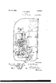
- Fig. 1 is a side elevation of a motor controller of the potential type
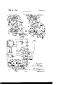
- Fig. 2 shows the operating mechanism of ihe controller illustrated in Fig. 1, the parts being in the position which they as- Serial No. 334,887.
- Fig. 3 is a view similar to Fig. 2 but showing the parts in the position which they assume when the operating handle has been thrown to running position.
- Fig. 4 is a front elevation of the conlroller illustrated in Fig. 1, parts being broken away and parts being in section.
- Fig. 5 is a detail of a movable contact element.
- the controller is provided with an operating handle 6 fastened to a main shaft 25, which latter carries an operating arm 20 here shown as provided with a projection 26 serving as a crank for moving the double link 28 pivoted thereto at the pin 27.
- the links 28 are pivoted at the other end to one end of the bell crank lever 43 which bell crank is mounted on a shaft 42, journalled in any suitable manner as, for example, in the end plates 30, indicated in dot and dash lines on Fig. l.
- the other end of the bell crank 43 carries a shaft 50, here shown as of square cross section.
- the shaft 50 has rounded ends 49, journalled for pivotal movement in the lower arm of the bell crank, as viewed in Fig. 1.
- a lever 51 is mounted for movement about a pivot 52 and is connected to the lower arm of the bell crank 43 and the shaft 50 associated therewith by means of a link 44.
- the link 44 is rigidly associated with the shaft 50 but is freel ⁇ , pivoted at ,45 to the lever 51.
- the square shaft 50 carries one or more movable contacts 47 fastened thereto by means of the clamping members 48, 54.
- Flexible leads 53 may be electrically connected to each movable contact member 47 by suitable terminals and these leads may be kept in the desired spaced alinement by means of a cleat 46.
- the movable contact or contacts are adapted to cooperate with relatively stationary contacts 38, 40. These contacts are mounted upon an insulating support 39. If more contacts are necessary or desirable, additional supports may be added or the support 39 may be lengthened. Contacts 38, 40 are each provided with a threaded shank 36, 37 respectively, passing through openings in both the insulating support 39 and the U-shaped clamps 32. The clamps 32 are adapted to be slipped over rods 31,
- the clamps 32 may be insulated from the rods 31, ll, by members 62.
- the contacts, insulating support and clamps may be fastened to the rods by tightening a nut 33 associated with each contact.
- Conductors 3 1 may be electrically connected to each contact and fastened thereto by nuts 35.
- the operating arm 20 is biased to circuit opening or off position by means of a centering dog, the elements 22,24, of which are drawn toward each other by means of the spring 59, and are pivotally mounted on shaft 25.
- the dog acts upon the operating arm 20 through the jaws 21, 23 and the pin or projection 17 carried by said operating arm.
- a stationary pin 18 is provided for holding one of the elements of the dog when the other is being moved.
- Latch means 8 is freely pivoted on shaft 11 and has a notch 16 therein ada ited to cooperate with pin 17 on the operating arm 20 so that the latter cannot be moved in a clockwise direction from the position shown in Fig. 1.
- the latch means is also provided with a cam surface 60, preferably eccentric with the operating arm 20 so that when the latter is moved in a counter-clockwise direction the latch means will be lifted.
- a notch 19 is provided in the cam surface 60 for a purpose to be hereinafter set forth.
- Holding and controlling means is provided for retaining the operating mechanism in its running position after the same has been moved there by an operator, com prising, in the instance shown, a low voltage magnet 5 having an armature 9 co-operating therewith.
- the armature 9 is fixed to the shaft 11 and its downward motion is limited by means of the pin 15 mounted in the brackets 14 between which the armature .9 swings.
- the holding means further comprises a latch member 13 having a slot therein the surfaces 10, 12 of which are at an angle with the general direction of motion of the pin 17 on the operating arm 20.
- the controller may, if desired, be provided with an overload coil 55 adapted to actuate contacts 3 to cause deenei ization of the low voltage magnet
- a dash pot may be provided for causing the overload coil to act with a time element.
- an auto-transformer i mounted in the same casing 1 as the switch or controller may be provided.
- the various leads may be brought into the casing through an opening 2 therein.
- the lower half 61, see Figs. 1 and 1, of the casing is detachable and may be held to the main portion thereof by means of the toggle device 57, 58.
- the casing 61 may or may not contain oil as desired.
- the operation of the controller illustrated is as follows: Assuming that the electrical connections are such that when the movable contacts -17 are connected to the contacts 40 the connected motor will be supplied with starting potential, the handle 6 will be thrown in a counter-clockwise direction from the position shown in Fig. 1 to that shown in Fig. 2, in order to start the motor. This motion is resisted by the jaw 23 of the dog acting against the pin 17, the jaw 21 remaining in its initial position, being stopped there by the lit-ted pin 18. Counter-clockwise movement of the operating arm 20 causes similar movement of the projection 26, this motion being transmitted to the bell crank l3 which rotates in the same direction.
- the distance the movable contact 47 moves away from any given relatively stationary contact is not dependent upon the distance between the relatively stationary contacts and in this manner prevention of arcing may be readily taken care of.
- the notch 19 in the latch means 8 is provided. It will be seen that if the operating arm 20 is moved the fraction of the distance from the starting position shown in Fig. 2 to the off position whereby the latch means 8' will drop down so that the notch 19 will engage the pin 17, the operating arm 20 cannot be again moved in a counter-clockwise direction from that position, inasmuch as the latch means 8 and the notch 19 then act as a latch pivoted at 11. The operating arm 20 is however free to move in a clockwise direction from this position to the off position.
- Comparatively rapid motion of the operating arm 20 from off position to starting position will cause the pin 17 to throw latch means 8 upward so that notch 19 will not engage pin 17.
- the position of the notch 19 may be at any desired point but is preferably so chosen that when the pin 17 is in the notch 19 the contacts 47 will be outside of arc ing distance.
- a switch comprising two sets of relatively stationary contact means having the centers of their effective contact surfaces spaced apart a given distance, movable contact means having an open circuit position outside of a semi-circle having a diameter equal to said distance and in a plane perpendicular to said surfaces, and means whereby said movable contact means is caused to execute a combined motion of translation and rotation in moving directly from said open circuit position into engagement with either of said relatively stationary contact means.
- a double-throw switch comprising two sets of relatively stationary contact means, movable contact means having an open circuit position, and actuating means for said movable contact means whereby said movable contact means is caused to execute a combined motion of translation and rotation in moving directly from said open circuit position into engagement with either of said relatively stationary contact means, said actuating means having axes of operation all of which are disposed outside of the space between the axial general planes of said sets.
- a double-throw switch comprising two sets of relatively stationary contact means, a crank having its axis disposed outside of the space between the axial general planes of said sets, means associated with said crank for swinging the same, movable contact means, having an open circuit position,
- a double throw switch comprising two sets of relatively stationary contact means, a crank having its axis disposed outside of the space between the axial general planes of said sets, means associated vith said crank for swinging the same, movable contact means having an open circuit position outside of the contact-plane of either or" said sets, operable by said crank, and means whereby when said crank is swung said movable contact means may be moved into engagement with one of said relatively stationary contact means directly from its open circuit position and then through said open circuit position to engagement with the other of said relatively stationary contact means.
- a double-throw switch comprising two sets of relatively stationary contact means, a crank having its axis disposed outside of the space between the axial general planes of said sets, means associated with said crank for swinging the same, movable contact means, having an open circuit position outside of the contact-plane of either of said sets, said movable contact means being carried by and pivotally associated with said crank, means whereby when said crank is swung said movable contact means may be moved into engagement with one of said relatively stationary contact means directly from its open circuit position and then through said open circuit position to engagement with the other of said relatively stationary contact means.
- a switch comprising a crank, means as sociated with said crank for swinging the same, a pivot carried by said crank, a contact mounted for rotation about the axis of said pivot, a lever having a stationary pivot, said lever extending from its pivot in a direction substantially opposite from that of a line from the axis of rotation of said crank to said pivotcarried thereby, and a link connecting said contact and said lever.
- a switch comprising a crank, means associated with said crank tor swinging the same, a lever having a stationary pivot, a support journalled in said crank, a contact mounted on said support, and a link rigidly associated'with said support and connected to said stationarypivot lever.
- A'switch comprising a crank, means associated with said crank tor swinging the same, a lever having a stationary pivot, a shaft journalled in said crank, a contact mounted on said shaft, and a link rigidly associated with said shaft and connected to said stationary-pivot lever.
- a switch comprising a crank, means associated with said crank for swinging the same, a lever having a stationary pivot, a link for connecting said lever with a point on said crank located in a direction from the axis of rotation of said crank substantially opposite from the direction in which said lever extends from its stationary pivot, and a contact associated with said link.
- a switch comprising a bell crank lever, means associated with one arm of said bell crank for movin" the same, a lever having a stationary pivot, a support journalled in the other arm of said bell crank lever, a contact mounted on said support, and a link rigidly ssociated with said support and connected to said stationary-pivot lever.
- a switch comprising a bell crank lever, means associated with one arm of said bell crank for moving the same, a lever havinc" a stationary pivot, a shaft journalled in the other arm of said bell crank lover, a contact mounted on said shaft, and a link rigidly associated with said shaft and connected to said stationary-pivot lever.
- a switch comprising a bell crank lever, means associated with one arm of said bell crank for moving the same, a lever having a stationary pivot, said lever extending in a direction. from its stationary pivot substantially opposite from the direction of the other arm of said bell crank from its axis of rotation, a link for connecting said other arm of said bell crank with said stationarypivot lever, and a contact associated with said link.
- a switch operating mechanism having a circuit opening and a circuit closing position, means for holding said mechanism in circuit closing position comprising a cam member, a magnet and armature, means for actuating said cam member operatively associated with said mechanism, means for biasing said mechanism to the circuit opening position disposed to act directly on said cam actuating means, and means whereby when said cam is actuated by said mechanism the armature will be brought into cooperative relation with said magnet.
- a switch operating mechanism having a circuit opening and a circuit closing position
- an operating lever provided with a pin near one end thereof, means engaging said pin for biasing said lever to circuit opening position.
- a latch member for holding said lever in circuit closing position having a slot therein, one of the surfaces of which forms a cam whereby when said pin cooperates therewith the latch member will be raised, thereby causing the other surface of said slot to come into latching position with respect to another surface of said pin, a magnet and. armature, and means whereby when said latch member is operated by said pin said armature will be brought into cooperative relation with said magnet.
- switch operating means having off, starting and running positions, a switch contact movable in unison with said operating means, means for preventing movement of said operating means from the oit position into the running position, and means for preventing slow oscillation of said mechanism between the starting position and a position between the starting and oil positions.
- switch operating mechanism having oiif, starting and running positions, a switch contact movable in unison with said operating mechanism, means whereby said mechanism may be moved from the starting position to the running position and is prevented from being moved from the off position to the running position, and means for preventing the slow oscillation of said mechanism between the starting position and a position between the starting and OK positions.
- a switch operating mechanism having oft, starting and running positions, a switch contact movable in unison with said operating mechanism, and means for preventing slow oscillation of said mechanism between the starting position and a position between the starting and off positions.
- a switch operating mechanism having oft, starting and running positions, a switch contact movable in unison with said operating mechanism, and means for preventing slow oscillation of said mechanism between the starting position and a position between the starting and off positions while permitting rapid motion between the starting and oil positions.
- a switch operating mechanism having off, starting and running positions, means for permitting the movement of said mechanism from rest in said off position into complete starting position at a relatively high speed and for stoppinpsaid mechanism short of complete starting position when said mechanism is moved at a predetermined lower speed.
- a switch operating mechanism having oil, starting and run ning positions, means for preventing movement of said mechanism into running posi tion without first moving into starting position
- a latch having a cut-away portion having walls the general planes of which are approximately at right angles to each other, one of said walls serving to engage said mechanism in off position and preventing movement to running position and the other of said walls constituting a cam surface eccentric to said operating mechanism and extending to the position said operating mechanism assumes when in starting position, the degree oi said eccentricity being sutiicient to hold said first named wall out of engaging position when said mechanism is in starting position.
- a switch operating lever having off, starting and running positions
- latch means for cooperating with said lever comprising a pivoted member having a shoulder engaging said lever in off position and preventing movement to running position, and having a substantially circular surface begun at the bottom of said shoulder and extended for engagement with said lever when in siarting position, said surface being. eccentric with said lever thereby acting as a cam surface of gradual lift.
- a switch operating lever having oil, starting and running posi tions
- latch means for cooperating with said lever comprising a pivoted member having a shoulder engaging said lever in off position and preventing movement to running position, and having a cam surface eccentric to said operating lever whereby said latch means is lifted when said lever is in starting position, and a notch in said cam surface.
Landscapes
- Mechanisms For Operating Contacts (AREA)
Description
Feb. 23,.1926. 4 1,574,417
H/W. CHENEY SWITCH Filed Oct. 29, 1919 2 Sheets-Sheet 1 Patented Feb. 23, 1926.
UNITED STATES PATENT OFFICE.
HERBERT W. CHENEY, OF MILWAUKEE, WISCONSIN, ASSIGNOR TO ALLIS-CHALMEBS MANUFACTURING COLIPANY, OF MILWAUKEE, "WISCONSIN, A CORPORATION OF DELAJVARE.
SWITCH.
, Application filed October 29, 1919.
To aZZ whom it may concern:
Be it known that HERBERT TV. CHENEY, a citizen of the United States of America, re siding at Milwaukee, in the county of Milwaukee and State of Wisconsin, has invented certain new and useful Improvement in Switches, of which the following is a specification.
This invention relates to switches or controllers and is particularly applicable to motor controllers or switches involving two circuit closing positions, one of which, in motor controllers, is usually a starting position and the other a running position.
One of the objects of this invention is the provision of a switch or controller having a simple and eflicient operating and controlling mechanism, and particularly an operating mechanism requiring small forces to operate the same.
Another object is the provision of a structure in which use is made: of butt contacts and more particularly 'a structure of this type involving two or more relatively stationary contacts in combination with one or more movable contacts, each one of which latter is adapt-ed to make contact with either one of a pair of the relatively stationary contacts. Another object of the invention is the provision of an operating mechanism for the movable contact or contacts whereby the desired movements will be secured.
Still another object of the invention is the provision of a simple and efiiclent contact structure. Other objects will appear hereinafter as the description of the invention proceeds.
The novel features of this invention will appear from the specification and the accompanying drawings forming a part thereof and disclosing one embodiment of said invention, and all these novel features are intended to be pointed out in the claims.
In the drawings Fig. 1 is a side elevation of a motor controller of the potential type,
embodying the invention, some of the elements being in section, which section is taken on the line II of Fig. 4, and the parts being shown in the open circult posi-.
tion in Fig. 1, and in the starting position in Fig. 4.
Fig. 2 shows the operating mechanism of ihe controller illustrated in Fig. 1, the parts being in the position which they as- Serial No. 334,887.
sume when the operating handle is thrown to starting position.
Fig. 3 is a view similar to Fig. 2 but showing the parts in the position which they assume when the operating handle has been thrown to running position.
Fig. 4 is a front elevation of the conlroller illustrated in Fig. 1, parts being broken away and parts being in section.
Fig. 5 is a detail of a movable contact element.
The controller is provided with an operating handle 6 fastened to a main shaft 25, which latter carries an operating arm 20 here shown as provided with a projection 26 serving as a crank for moving the double link 28 pivoted thereto at the pin 27. The links 28 are pivoted at the other end to one end of the bell crank lever 43 which bell crank is mounted on a shaft 42, journalled in any suitable manner as, for example, in the end plates 30, indicated in dot and dash lines on Fig. l. The other end of the bell crank 43 carries a shaft 50, here shown as of square cross section. The shaft 50 has rounded ends 49, journalled for pivotal movement in the lower arm of the bell crank, as viewed in Fig. 1. A lever 51 is mounted for movement about a pivot 52 and is connected to the lower arm of the bell crank 43 and the shaft 50 associated therewith by means of a link 44. The link 44 is rigidly associated with the shaft 50 but is freel}, pivoted at ,45 to the lever 51.
The square shaft 50 carries one or more movable contacts 47 fastened thereto by means of the clamping members 48, 54. Flexible leads 53 may be electrically connected to each movable contact member 47 by suitable terminals and these leads may be kept in the desired spaced alinement by means of a cleat 46.
The movable contact or contacts are adapted to cooperate with relatively stationary contacts 38, 40. These contacts are mounted upon an insulating support 39. If more contacts are necessary or desirable, additional supports may be added or the support 39 may be lengthened. Contacts 38, 40 are each provided with a threaded shank 36, 37 respectively, passing through openings in both the insulating support 39 and the U-shaped clamps 32. The clamps 32 are adapted to be slipped over rods 31,
41 supported in any suitable manner as in the end plates 30. The clamps 32 may be insulated from the rods 31, ll, by members 62. The contacts, insulating support and clamps may be fastened to the rods by tightening a nut 33 associated with each contact. Conductors 3 1 may be electrically connected to each contact and fastened thereto by nuts 35.
The operating arm 20 is biased to circuit opening or off position by means of a centering dog, the elements 22,24, of which are drawn toward each other by means of the spring 59, and are pivotally mounted on shaft 25. The dog acts upon the operating arm 20 through the jaws 21, 23 and the pin or projection 17 carried by said operating arm. A stationary pin 18 is provided for holding one of the elements of the dog when the other is being moved.
Latch means 8 is freely pivoted on shaft 11 and has a notch 16 therein ada ited to cooperate with pin 17 on the operating arm 20 so that the latter cannot be moved in a clockwise direction from the position shown in Fig. 1. The latch means is also provided with a cam surface 60, preferably eccentric with the operating arm 20 so that when the latter is moved in a counter-clockwise direction the latch means will be lifted. A notch 19 is provided in the cam surface 60 for a purpose to be hereinafter set forth.
Holding and controlling means is provided for retaining the operating mechanism in its running position after the same has been moved there by an operator, com prising, in the instance shown, a low voltage magnet 5 having an armature 9 co-operating therewith. The armature 9 is fixed to the shaft 11 and its downward motion is limited by means of the pin 15 mounted in the brackets 14 between which the armature .9 swings. The holding means further comprises a latch member 13 having a slot therein the surfaces 10, 12 of which are at an angle with the general direction of motion of the pin 17 on the operating arm 20.
The controller may, if desired, be provided with an overload coil 55 adapted to actuate contacts 3 to cause deenei ization of the low voltage magnet A dash pot may be provided for causing the overload coil to act with a time element.
Wherethe control of the motor is to be by variation of the potential supplied there to, an auto-transformer i mounted in the same casing 1 as the switch or controller may be provided. The various leads may be brought into the casing through an opening 2 therein.
The lower half 61, see Figs. 1 and 1, of the casing is detachable and may be held to the main portion thereof by means of the toggle device 57, 58. The casing 61 may or may not contain oil as desired.
The operation of the controller illustrated is as follows: Assuming that the electrical connections are such that when the movable contacts -17 are connected to the contacts 40 the connected motor will be supplied with starting potential, the handle 6 will be thrown in a counter-clockwise direction from the position shown in Fig. 1 to that shown in Fig. 2, in order to start the motor. This motion is resisted by the jaw 23 of the dog acting against the pin 17, the jaw 21 remaining in its initial position, being stopped there by the lit-ted pin 18. Counter-clockwise movement of the operating arm 20 causes similar movement of the projection 26, this motion being transmitted to the bell crank l3 which rotates in the same direction. By reason of its connection with the link 14: the lower end of the bell crank as causes said link to move, in general, to the right, thus also shifting the contact at to the right from its positicn as shown in Fig. 1. YVhile the contact 4 7 and the link 1 1 are thus being shifted to the right the pivot-end 4:5 of said linl; is being pulled downward by the clockwise rotation of the lever- 51. This causes a clockwise rotation of the link i l and consequently a similar rotation of the shaft 50 associated therewith, result ing in an upward movement of the contact l7 bringing the latter into engagement with the contact 40.
Vfhilc the operating arm 20 moved from its position in "1 to the position in Fig. 2 the pin 17 acted upon the cam surface 60 of the latch means 8 raising the latter about its pivot 11 to the position shown in Fig. 2. If the handle 6 is now moved rapidly in a clockwise direction the operating arm 20 will moveinto the position shown in Fig. 3, the pin 17 passing underneath the projection formed by the notch 16, the inertia of the latch means 8 being sufiicient to prevent the latter from dropping down soon enough to cause the notch 16 to engage the pin 17. As the operating arm 20 moves into the position shown in 3 thepin 17 enters the slot in the latch member 13 and engages the surface 10 of said slot, thus raising the latch member and consequently also the armature 9 by reason of the rotation of the shaft 11. As the latch member 13 is thus rotated in a clockwise direction, the surface 12 of the slot therein comes into cooperative position with an opposite face of the pin 17 and as the low voltage magnet 5 has now been energized by any suitable electrical connections, and the armature is being held in the position shown in Fig. 3 by the said magnet, the surface 12 will prevent counter-clockwise motion of the operating arm 20, although biased in that direction by the aw 21, when the handle 6 is released by the operator. lVealzening of magnet 5 to a predetermined extent will clearly permit pin 17 to force-latch me1nber 13 downward and so permit return of the operative arm to oil? position.
While the operating arm 20 moves from the position shown in Fig. 2 to the position shown in Fig. 3, it passes through the of? position and consequently brings the contacts 47 back to the position indicated in Fig. 1; from that position the contacts 47 will be moved to the left and simultaneously in an upward direction into engagement with the contacts 38, the action of the link mechanism being similar to that already described in connection with the movement from the oil to the starting position.
It will be noted that by reason of the provision of the novel type of operating mechanism for the movable contacts it is possible to use a contact having a single contact face for cooperating with two relatively stationary contacts, thus simplifying and cheapening the movable contact mechanism and avoiding the use o1 either two butt contacts on the movable member, one of which engages a relatively stationary contact in one circuit closing position and the other of which engages a corresponding relatively stationary contact in another circuit closing position, or the use of a knife blade type of movable contact, which, particularly in switches and controllers handling heavy currents, is open to the objection that friction between the knife blade contacts and the relatively stationary contact clips becomes so large as to render the necessary operating mechanism and manual force actuating the same prohibitively large. The present invention combines the advantages of a sliding butt contact construction with a simplicity superior to the knife blade construction, without the disadvantages of either. By reason of the butting contacts small forces only are necessary to disenthe same'and bring the same into engagement.
It wil be further noted that the distance the movable contact 47 moves away from any given relatively stationary contact is not dependent upon the distance between the relatively stationary contacts and in this manner prevention of arcing may be readily taken care of.
The contact surfaces are kept clean for, as may be seen from an inspection of either Figs. 2 or 3, after contact 47 has engaged either contact 38 or 40, slight relative rubbing motion between the two is possible by reason or" the horizontal component given the movable contact by the bell crank 43.
In order to prevent an operator from throwing current on to a connected motor and then moving the controller a slight distance toward the off position, and back into the starting position, thus causing arcing between the movable and starting contacts, the notch 19 in the latch means 8 is provided. It will be seen that if the operating arm 20 is moved the fraction of the distance from the starting position shown in Fig. 2 to the off position whereby the latch means 8' will drop down so that the notch 19 will engage the pin 17, the operating arm 20 cannot be again moved in a counter-clockwise direction from that position, inasmuch as the latch means 8 and the notch 19 then act as a latch pivoted at 11. The operating arm 20 is however free to move in a clockwise direction from this position to the off position. Comparatively rapid motion of the operating arm 20 from off position to starting position will cause the pin 17 to throw latch means 8 upward so that notch 19 will not engage pin 17. The position of the notch 19 may be at any desired point but is preferably so chosen that when the pin 17 is in the notch 19 the contacts 47 will be outside of arc ing distance.
It should be understood that it is not desired to limit the invention claimed to the exact details of construction herein shown and described, for obvious modifications may occur to persons skilled in the art.
It is claimed and desired to secure by Letters Patent:
1. A switch comprising two sets of relatively stationary contact means having the centers of their effective contact surfaces spaced apart a given distance, movable contact means having an open circuit position outside of a semi-circle having a diameter equal to said distance and in a plane perpendicular to said surfaces, and means whereby said movable contact means is caused to execute a combined motion of translation and rotation in moving directly from said open circuit position into engagement with either of said relatively stationary contact means.
2. A double-throw switch comprising two sets of relatively stationary contact means, movable contact means having an open circuit position, and actuating means for said movable contact means whereby said movable contact means is caused to execute a combined motion of translation and rotation in moving directly from said open circuit position into engagement with either of said relatively stationary contact means, said actuating means having axes of operation all of which are disposed outside of the space between the axial general planes of said sets.
3. A double-throw switch comprising two sets of relatively stationary contact means, a crank having its axis disposed outside of the space between the axial general planes of said sets, means associated with said crank for swinging the same, movable contact means, having an open circuit position,
operable by said crank, and means whereby when said crank is swung said movable contact means is caused to execute a combined motion or" translation and rotation in moving directly from said open circuit position into engagement with either of said relatively stationary contact means.
4L. A double throw switch comprising two sets of relatively stationary contact means, a crank having its axis disposed outside of the space between the axial general planes of said sets, means associated vith said crank for swinging the same, movable contact means having an open circuit position outside of the contact-plane of either or" said sets, operable by said crank, and means whereby when said crank is swung said movable contact means may be moved into engagement with one of said relatively stationary contact means directly from its open circuit position and then through said open circuit position to engagement with the other of said relatively stationary contact means.
5. A double-throw switch comprising two sets of relatively stationary contact means, a crank having its axis disposed outside of the space between the axial general planes of said sets, means associated with said crank for swinging the same, movable contact means, having an open circuit position outside of the contact-plane of either of said sets, said movable contact means being carried by and pivotally associated with said crank, means whereby when said crank is swung said movable contact means may be moved into engagement with one of said relatively stationary contact means directly from its open circuit position and then through said open circuit position to engagement with the other of said relatively stationary contact means.
6. A switch comprising a crank, means as sociated with said crank for swinging the same, a pivot carried by said crank, a contact mounted for rotation about the axis of said pivot, a lever having a stationary pivot, said lever extending from its pivot in a direction substantially opposite from that of a line from the axis of rotation of said crank to said pivotcarried thereby, and a link connecting said contact and said lever.
7. A switch comprising a crank, means associated with said crank tor swinging the same, a lever having a stationary pivot, a support journalled in said crank, a contact mounted on said support, and a link rigidly associated'with said support and connected to said stationarypivot lever.
8. A'switch comprising a crank, means associated with said crank tor swinging the same, a lever having a stationary pivot, a shaft journalled in said crank, a contact mounted on said shaft, and a link rigidly associated with said shaft and connected to said stationary-pivot lever.
9. A switch comprising a crank, means associated with said crank for swinging the same, a lever having a stationary pivot, a link for connecting said lever with a point on said crank located in a direction from the axis of rotation of said crank substantially opposite from the direction in which said lever extends from its stationary pivot, and a contact associated with said link.
10. A switch comprising a bell crank lever, means associated with one arm of said bell crank for movin" the same, a lever having a stationary pivot, a support journalled in the other arm of said bell crank lever, a contact mounted on said support, and a link rigidly ssociated with said support and connected to said stationary-pivot lever.
11. A switch comprising a bell crank lever, means associated with one arm of said bell crank for moving the same, a lever havinc" a stationary pivot, a shaft journalled in the other arm of said bell crank lover, a contact mounted on said shaft, and a link rigidly associated with said shaft and connected to said stationary-pivot lever.
12. A switch comprising a bell crank lever, means associated with one arm of said bell crank for moving the same, a lever having a stationary pivot, said lever extending in a direction. from its stationary pivot substantially opposite from the direction of the other arm of said bell crank from its axis of rotation, a link for connecting said other arm of said bell crank with said stationarypivot lever, and a contact associated with said link.
13. In combination, a switch operating mechanism having a circuit opening and a circuit closing position, means for holding said mechanism in circuit closing position comprising a cam member, a magnet and armature, means for actuating said cam member operatively associated with said mechanism, means for biasing said mechanism to the circuit opening position disposed to act directly on said cam actuating means, and means whereby when said cam is actuated by said mechanism the armature will be brought into cooperative relation with said magnet.
1- 1. In combination, a switch operating mechanism having a circuit opening and a circuit closing position comprising an operating lever provided with a pin near one end thereof, means engaging said pin for biasing said lever to circuit opening position. a latch member for holding said lever in circuit closing position having a slot therein, one of the surfaces of which forms a cam whereby when said pin cooperates therewith the latch member will be raised, thereby causing the other surface of said slot to come into latching position with respect to another surface of said pin, a magnet and. armature, and means whereby when said latch member is operated by said pin said armature will be brought into cooperative relation with said magnet.
15. In combination, switch operating means having off, starting and running positions, a switch contact movable in unison with said operating means, means for preventing movement of said operating means from the oit position into the running position, and means for preventing slow oscillation of said mechanism between the starting position and a position between the starting and oil positions.
16. In combination, switch operating mechanism having oiif, starting and running positions, a switch contact movable in unison with said operating mechanism, means whereby said mechanism may be moved from the starting position to the running position and is prevented from being moved from the off position to the running position, and means for preventing the slow oscillation of said mechanism between the starting position and a position between the starting and OK positions.
17. In combination a switch operating mechanism having oft, starting and running positions, a switch contact movable in unison with said operating mechanism, and means for preventing slow oscillation of said mechanism between the starting position and a position between the starting and off positions.
18. In combination, a switch operating mechanism having oft, starting and running positions, a switch contact movable in unison with said operating mechanism, and means for preventing slow oscillation of said mechanism between the starting position and a position between the starting and off positions while permitting rapid motion between the starting and oil positions.
19. In combination, a switch operating mechanism having off, starting and running positions, means for permitting the movement of said mechanism from rest in said off position into complete starting position at a relatively high speed and for stoppinpsaid mechanism short of complete starting position when said mechanism is moved at a predetermined lower speed.
20. In combination, a switch operating mechanism having oil, starting and run ning positions, means for preventing movement of said mechanism into running posi tion without first moving into starting position comprising a latch having a cut-away portion having walls the general planes of which are approximately at right angles to each other, one of said walls serving to engage said mechanism in off position and preventing movement to running position and the other of said walls constituting a cam surface eccentric to said operating mechanism and extending to the position said operating mechanism assumes when in starting position, the degree oi said eccentricity being sutiicient to hold said first named wall out of engaging position when said mechanism is in starting position.
21. In combination, a switch operating lever, having off, starting and running positions, latch means for cooperating with said lever comprising a pivoted member having a shoulder engaging said lever in off position and preventing movement to running position, and having a substantially circular surface begun at the bottom of said shoulder and extended for engagement with said lever when in siarting position, said surface being. eccentric with said lever thereby acting as a cam surface of gradual lift.
22. In combination, a switch operating lever, having oil, starting and running posi tions, latch means for cooperating with said lever comprising a pivoted member having a shoulder engaging said lever in off position and preventing movement to running position, and having a cam surface eccentric to said operating lever whereby said latch means is lifted when said lever is in starting position, and a notch in said cam surface.
In testimony whereof, the signature of the inventor is aiiixed hereto.
HERBERT vV. CHENEY.
Priority Applications (2)
| Application Number | Priority Date | Filing Date | Title |
|---|---|---|---|
| US334887A US1574417A (en) | 1919-10-29 | 1919-10-29 | Switch |
| US483732A US1735263A (en) | 1919-10-29 | 1921-07-11 | Contact mechanism |
Applications Claiming Priority (1)
| Application Number | Priority Date | Filing Date | Title |
|---|---|---|---|
| US334887A US1574417A (en) | 1919-10-29 | 1919-10-29 | Switch |
Publications (1)
| Publication Number | Publication Date |
|---|---|
| US1574417A true US1574417A (en) | 1926-02-23 |
Family
ID=23309293
Family Applications (1)
| Application Number | Title | Priority Date | Filing Date |
|---|---|---|---|
| US334887A Expired - Lifetime US1574417A (en) | 1919-10-29 | 1919-10-29 | Switch |
Country Status (1)
| Country | Link |
|---|---|
| US (1) | US1574417A (en) |
-
1919
- 1919-10-29 US US334887A patent/US1574417A/en not_active Expired - Lifetime
Similar Documents
| Publication | Publication Date | Title |
|---|---|---|
| US1574417A (en) | Switch | |
| US2108634A (en) | Mechanical interlock | |
| US2260025A (en) | Electric controller | |
| US2312243A (en) | Circuit controlling device | |
| US1518701A (en) | Quick-acting-switch mechanism | |
| US1480394A (en) | Snap switch | |
| US2671141A (en) | Switch operating means | |
| US1077380A (en) | Quick-break switching mechanism. | |
| US1790689A (en) | Isolated-phase-switching apparatus | |
| US1450899A (en) | Switch | |
| US1103528A (en) | Current-controlling apparatus. | |
| US1522766A (en) | Selective switch | |
| US831404A (en) | Controlling-switch. | |
| US1738406A (en) | Electric switch and operating means therefor | |
| US1448383A (en) | Switching device | |
| US2443991A (en) | Relay | |
| US1768461A (en) | Switch-operating mechanism | |
| US1547835A (en) | Electrical controlling mechanism | |
| US1470896A (en) | Starting switch | |
| US1858242A (en) | Snap operating mechanism | |
| US2316678A (en) | Circuit controller | |
| US1719302A (en) | Circuit maker and breaker | |
| US1578878A (en) | Electromagnetic switch mechanism | |
| US1806377A (en) | Friction switch mechanism | |
| US1494052A (en) | Controller |