US1551925A - Headlight-shifting apparatus - Google Patents
Headlight-shifting apparatus Download PDFInfo
- Publication number
- US1551925A US1551925A US733530A US73353024A US1551925A US 1551925 A US1551925 A US 1551925A US 733530 A US733530 A US 733530A US 73353024 A US73353024 A US 73353024A US 1551925 A US1551925 A US 1551925A
- Authority
- US
- United States
- Prior art keywords
- headlight
- stem
- shifting apparatus
- link
- leg
- Prior art date
- Legal status (The legal status is an assumption and is not a legal conclusion. Google has not performed a legal analysis and makes no representation as to the accuracy of the status listed.)
- Expired - Lifetime
Links
- 238000010276 construction Methods 0.000 description 3
- 101100240595 Mus musculus Nipal4 gene Proteins 0.000 description 1
- 238000004519 manufacturing process Methods 0.000 description 1
Images
Classifications
-
- B—PERFORMING OPERATIONS; TRANSPORTING
- B60—VEHICLES IN GENERAL
- B60Q—ARRANGEMENT OF SIGNALLING OR LIGHTING DEVICES, THE MOUNTING OR SUPPORTING THEREOF OR CIRCUITS THEREFOR, FOR VEHICLES IN GENERAL
- B60Q1/00—Arrangement of optical signalling or lighting devices, the mounting or supporting thereof or circuits therefor
- B60Q1/02—Arrangement of optical signalling or lighting devices, the mounting or supporting thereof or circuits therefor the devices being primarily intended to illuminate the way ahead or to illuminate other areas of way or environments
- B60Q1/04—Arrangement of optical signalling or lighting devices, the mounting or supporting thereof or circuits therefor the devices being primarily intended to illuminate the way ahead or to illuminate other areas of way or environments the devices being headlights
- B60Q1/06—Arrangement of optical signalling or lighting devices, the mounting or supporting thereof or circuits therefor the devices being primarily intended to illuminate the way ahead or to illuminate other areas of way or environments the devices being headlights adjustable, e.g. remotely-controlled from inside vehicle
- B60Q1/08—Arrangement of optical signalling or lighting devices, the mounting or supporting thereof or circuits therefor the devices being primarily intended to illuminate the way ahead or to illuminate other areas of way or environments the devices being headlights adjustable, e.g. remotely-controlled from inside vehicle automatically
- B60Q1/12—Arrangement of optical signalling or lighting devices, the mounting or supporting thereof or circuits therefor the devices being primarily intended to illuminate the way ahead or to illuminate other areas of way or environments the devices being headlights adjustable, e.g. remotely-controlled from inside vehicle automatically due to steering position
- B60Q1/124—Arrangement of optical signalling or lighting devices, the mounting or supporting thereof or circuits therefor the devices being primarily intended to illuminate the way ahead or to illuminate other areas of way or environments the devices being headlights adjustable, e.g. remotely-controlled from inside vehicle automatically due to steering position by mechanical means
Definitions
- This invention relates to a headlight shifting apparatus for motor vehicles, and the primary object thereof is to provide a device of'the class stated, in a manner as herein after set forth, which is operably connected to the steering mechanism of the motor vehicle to automatically shift the vehicle headlights to correspond to the steering movement of the front wheels of the vehicle, under such conditions projecting the rays of light from the headlights in alignment with the front wheels of the veliicle,whereby the direct path of travel will'be clearly visible to the operator of the vehicle at all times and consequently minimizing accidents attending motor vehicle operations at night.
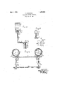
- Figure 1 is a side view of a headlight shifting apparatus in accordance with my invention.
- Figure 2 is a front view thereof.
- Figure 3 is an enlarged rear view of the compensating link and guide plate.
- Figure 4 is a top plan view of the guide plate.
- FIG. 1 denotes a motor vehicle headlight of the usual construction and mounted on a horizontally disposed supporting bar 2 which latter is provided with angularly disposed end portions 3 by which the supporting bar 2 is adapted to be rigidly secured to the mud guards or fenders of the motor vehicle.
- the headlight 1 is formed on its lower end with a depending neck 4 and is shiftably mounted on the supporting bar 2 by neans of the operating lever 5.
- the latter is substantially L-shaped consisting of a vertically disposed leg 6 and a rearwardly projecting horizontally disposed leg 7.
- the upper e'ndof the vertical leg 6 extends through an aperture 8 in the supporting bar 2 and is fixed in the depending neck 4 of the headlight by a pin 9.
- the vertical leg 6,. of the operating lever 5, is rotatably mounted in the aperture 8 of the supporting bar 2, and a washer 10 is p0- sitioned between the lower face of the neck 4 and the, upper face of the supporting bar 2.
- the vertical leg 6 is adjusted for rotation in the aperture 8 and is locked against vertical movement therein, by means of a pair of nuts 11, which engage the threaded portion 12 of the vertical leg 6.
- a Washer 13 is interposed between the lower face of the supporting bar 2 and the nuts 11.
- Thehorizontal-leg 7 is formed with a reduced rear portion 14, having a threaded end 15 carrying a nut 16.
- a compensating link 17 is slidably mounted on the reduced portion 14 and is provided with a flat underface 18 and a depending stem 19 disposed centrally of the underface 18.
- a vertically disposed actuating arm 20 I I I consisting of a pair of spaced members 21 is fixedly secured to the parallel rod 20 which latter connects with steering knuckles of the motor vehicle.
- the free ends of the spaced members 21 engage respective sides of the parallel rod 30, and are securely clamped to the latter by means of the bolts 22, as clearly shown in Figure 1, of the drawing.
- the upper ends of the spaced member 21 are joined together to provide a flat top 23 which abuts against the fiat underface 18 of the link 17 during the operation of the apparatus.
- the top 23 is formed with a centrally disposed aperture for the reception of the link stem 18 which extends downwardly between the spaced members 21.
- the lowerend of the link stem 18 carries a slidably mounted guide plate 24.
- the latter is formed, with centrally dlfiPOSfidHWPGItIlIB 25, through which-the stem 18 extends:
- Icl'aim is; I V 1.
- actuating arm rigidly ,attachedi to; said" parallel rod, and a link including a stem slidably connected vwith saidlever-,-said stem extending into said arm and resiliently connected therewith.
- ai -In combination with a headlight, support therefor, and the parallel rod of the steering mechanism of a-niotor vehicle, a substantially L-shaped operating lever consisting of a vertical legan'd a horizontal'leg, the upper end of said vertical leg pivotally mounted" in said support and fixedly connectedto said headlight, said horizontal leg formed withfa reduced portion at. the rear endthereof, a vertically disposed actuating arm consistingof a pair' of spaced arm members rigidly clamped at its loweii end to said parallel" rod, a link slida'bly mounted. for horizontal movement onthe said reduced portion of saidlhorizonta'l leg, said link carrying" a: depending stem.
Landscapes
- Engineering & Computer Science (AREA)
- Mechanical Engineering (AREA)
- Lighting Device Outwards From Vehicle And Optical Signal (AREA)
Description
Sept 1, 1925.
D. BAUGHMAN HEADLIGHT SHIFTING APPARATUS Filed A112. 22, 1924 Patented Sept. 1, 1925.
UNITED STATES PATENT OFFICE.
HEADLIGHT-SHIFTING APPARATUS.
Application filed August 22, 1924. Serial No. 733,530.
To all whomz't may concern:
Be it known that 1, DAVID BAUGHMAN, a citizen of the United States, residing at Pittsburgh, in the county of Allegheny and State of Pennsylvania, have invented certain new and useful Improvements in Headlight- Shifting Apparatus, of which the following is a specification. i
This invention relates to a headlight shifting apparatus for motor vehicles, and the primary object thereof is to provide a device of'the class stated, in a manner as herein after set forth, which is operably connected to the steering mechanism of the motor vehicle to automatically shift the vehicle headlights to correspond to the steering movement of the front wheels of the vehicle, under such conditions projecting the rays of light from the headlights in alignment with the front wheels of the veliicle,whereby the direct path of travel will'be clearly visible to the operator of the vehicle at all times and consequently minimizing accidents attending motor vehicle operations at night.
Further objects of the invention are to provide a headlight shifting apparatus, which is simple in its construction and arrangement, strong, durable and eflicient in its use, compact, which may be installed to any type of motor vehicle, and which is comparatively inexpensive to manufacture and install.
With the foregoingand other objects in view which will appear, as the description proceeds, the invention resides in the details of construction hereinafter described and claimed, it being understood that changes in the precise embodiment of the invention herein disclosed can be made within the scope of the claims hereunto appended without departing from the spirit of the invention.
In the drawing forming. a portion of this specification and wherein like numerals of reference designate corresponding parts throughout the several views 1- Figure 1 is a side view of a headlight shifting apparatus in accordance with my invention.
Figure 2 is a front view thereof.
Figure 3 is an enlarged rear view of the compensating link and guide plate.
Figure 4 is a top plan view of the guide plate.
Referring in detail to the drawingl denotes a motor vehicle headlight of the usual construction and mounted on a horizontally disposed supporting bar 2 which latter is provided with angularly disposed end portions 3 by which the supporting bar 2 is adapted to be rigidly secured to the mud guards or fenders of the motor vehicle.
The headlight 1 is formed on its lower end with a depending neck 4 and is shiftably mounted on the supporting bar 2 by neans of the operating lever 5. The latter is substantially L-shaped consisting of a vertically disposed leg 6 and a rearwardly projecting horizontally disposed leg 7. The upper e'ndof the vertical leg 6 extends through an aperture 8 in the supporting bar 2 and is fixed in the depending neck 4 of the headlight by a pin 9. v
The vertical leg 6,. of the operating lever 5, is rotatably mounted in the aperture 8 of the supporting bar 2, and a washer 10 is p0- sitioned between the lower face of the neck 4 and the, upper face of the supporting bar 2. The vertical leg 6 is adjusted for rotation in the aperture 8 and is locked against vertical movement therein, by means of a pair of nuts 11, which engage the threaded portion 12 of the vertical leg 6. A Washer 13 is interposed between the lower face of the supporting bar 2 and the nuts 11.
Thehorizontal-leg 7 is formed with a reduced rear portion 14, having a threaded end 15 carrying a nut 16. A compensating link 17 is slidably mounted on the reduced portion 14 and is provided with a flat underface 18 and a depending stem 19 disposed centrally of the underface 18.
A vertically disposed actuating arm 20 I I I consisting of a pair of spaced members 21 is fixedly secured to the parallel rod 20 which latter connects with steering knuckles of the motor vehicle. The free ends of the spaced members 21 engage respective sides of the parallel rod 30, and are securely clamped to the latter by means of the bolts 22, as clearly shown in Figure 1, of the drawing.
The upper ends of the spaced member 21 are joined together to provide a flat top 23 which abuts against the fiat underface 18 of the link 17 during the operation of the apparatus. The top 23 is formed with a centrally disposed aperture for the reception of the link stem 18 which extends downwardly between the spaced members 21. The lowerend of the link stem 18 carries a slidably mounted guide plate 24. The latter is formed, with centrally dlfiPOSfidHWPGItIlIB 25, through which-the stem 18 extends: The
lower end of the stem 18 is formed with anaperture 26, in 'wh'ichn a pcotheii Pin- 2751181,
placed for maintaining the guide block 2 1 on the stem 18. The guide; block'24i lis'provided with a pair of recesses 28 formedin opposed side edges thereof 'Ijherecesses 28 providea noiseless tensioned conne'ctionhoii the, associated parts;
lVhen installing the shiftingapparatus to a vehicle,th e relative position of the link 17 to the actuatinf-garm ZO is'suchthatabout one-halt of the stein 18 will normally project abovethe top 23, 'ofthe arm 20, thereby permitting of the" vertical movement. of the stem 18 in the arm-20,130 compensate forthe usual vibration of the vehicle duringitsope, erat-ion. 4 The sliding connection ofthe link 17;'on the reduced lever'portion 1'6' and, itsypivotal connection with the actiiatinggarm 20 and guide platefQl, will allow for-the, free shifting of the operatinglever 5 in any direction without setting up any'bindinggaction of'the associated parts,
hat Icl'aim is; I V 1. In combination witha headliglihsup porting member therefor, and" the parallel rod'ofthe steering mechanismof a motor'vehicle', operating lever-pivot'ally mounted insaid supporting member and fixedly secured to said headlight, an actuating arm rigidly ,attachedi to; said" parallel rod, and a link including a stem slidably connected vwith saidlever-,-said stem extending into said arm and resiliently connected therewith.
ai -In combination, with a headlight, support therefor, and the parallel rod of the steering mechanism of a-niotor vehicle, a substantially L-shaped operating lever consisting of a vertical legan'd a horizontal'leg, the upper end of said vertical leg pivotally mounted" in said support and fixedly connectedto said headlight, said horizontal leg formed withfa reduced portion at. the rear endthereof, a vertically disposed actuating arm consistingof a pair' of spaced arm members rigidly clamped at its loweii end to said parallel" rod, a link slida'bly mounted. for horizontal movement onthe said reduced portion of saidlhorizonta'l leg, said link carrying" a: depending stem. pivotally engaging the top of said arm and extending between said spaced varm members, a" gui de plate slidably mounted for vertical movement between said spaced arm members and rotatably supported on thelow'er endiof said stennand a resilient member mounted on said stem'and interposed" between the top of said actuating. arm and the said guide plate, substantially as described and for the purpose set forth.
Intestimony whereof I'I'afliX my signature.
DAVID BAUGHMAN;
Priority Applications (1)
| Application Number | Priority Date | Filing Date | Title |
|---|---|---|---|
| US733530A US1551925A (en) | 1924-08-22 | 1924-08-22 | Headlight-shifting apparatus |
Applications Claiming Priority (1)
| Application Number | Priority Date | Filing Date | Title |
|---|---|---|---|
| US733530A US1551925A (en) | 1924-08-22 | 1924-08-22 | Headlight-shifting apparatus |
Publications (1)
| Publication Number | Publication Date |
|---|---|
| US1551925A true US1551925A (en) | 1925-09-01 |
Family
ID=24948006
Family Applications (1)
| Application Number | Title | Priority Date | Filing Date |
|---|---|---|---|
| US733530A Expired - Lifetime US1551925A (en) | 1924-08-22 | 1924-08-22 | Headlight-shifting apparatus |
Country Status (1)
| Country | Link |
|---|---|
| US (1) | US1551925A (en) |
-
1924
- 1924-08-22 US US733530A patent/US1551925A/en not_active Expired - Lifetime
Similar Documents
| Publication | Publication Date | Title |
|---|---|---|
| US1551925A (en) | Headlight-shifting apparatus | |
| US2207114A (en) | Signal system for motor-driven vehicles | |
| US1621920A (en) | Light mechanism for vehicles | |
| US1349415A (en) | Shock-absorbing steering mechanism | |
| US1600267A (en) | Dirigible headlight | |
| US1476656A (en) | Dirigible headlight | |
| US1614279A (en) | Steering device for vehicles | |
| US1602466A (en) | Safety rear-axle brace | |
| US1533957A (en) | Movable headlight | |
| US1434218A (en) | Headlight mechanism for vehicles | |
| US1968931A (en) | Automobile headlight | |
| US1364708A (en) | Dirigible light | |
| US1472875A (en) | Tiltable headlight | |
| US1543428A (en) | Automatic dirigible automobile headlight | |
| US1865294A (en) | Dirigible light | |
| US1082618A (en) | Lamp-bracket for power-driven vehicles. | |
| US1595879A (en) | Automobile headlight control | |
| US1598330A (en) | Dirigible headlight | |
| US1603252A (en) | Headlight mounting | |
| US1520425A (en) | Dirigible headlight | |
| US1790511A (en) | Bred jtosxph yzxbsoh | |
| US1672282A (en) | Controlling mechanism for headlights | |
| US1704046A (en) | Pivoting headlight | |
| US1454260A (en) | Dirigible headlight | |
| US1411924A (en) | Movable headlight |