US1546292A - Concrete-distributing machine - Google Patents
Concrete-distributing machine Download PDFInfo
- Publication number
- US1546292A US1546292A US546273A US54627322A US1546292A US 1546292 A US1546292 A US 1546292A US 546273 A US546273 A US 546273A US 54627322 A US54627322 A US 54627322A US 1546292 A US1546292 A US 1546292A
- Authority
- US
- United States
- Prior art keywords
- boom
- bucket
- carriage
- cable
- movement
- Prior art date
- Legal status (The legal status is an assumption and is not a legal conclusion. Google has not performed a legal analysis and makes no representation as to the accuracy of the status listed.)
- Expired - Lifetime
Links
- 230000007246 mechanism Effects 0.000 description 56
- 230000009471 action Effects 0.000 description 14
- 239000000543 intermediate Substances 0.000 description 13
- 230000001276 controlling effect Effects 0.000 description 10
- 230000006872 improvement Effects 0.000 description 6
- 238000000034 method Methods 0.000 description 4
- 230000003472 neutralizing effect Effects 0.000 description 4
- 230000000694 effects Effects 0.000 description 3
- 238000009877 rendering Methods 0.000 description 3
- 238000004804 winding Methods 0.000 description 3
- 241001527902 Aratus Species 0.000 description 2
- 238000007599 discharging Methods 0.000 description 2
- 230000000977 initiatory effect Effects 0.000 description 2
- 239000000463 material Substances 0.000 description 2
- 230000000979 retarding effect Effects 0.000 description 2
- 230000035939 shock Effects 0.000 description 2
- 102000004726 Connectin Human genes 0.000 description 1
- 108010002947 Connectin Proteins 0.000 description 1
- 238000013459 approach Methods 0.000 description 1
- 229940000425 combination drug Drugs 0.000 description 1
- 230000006835 compression Effects 0.000 description 1
- 238000007906 compression Methods 0.000 description 1
- 238000010276 construction Methods 0.000 description 1
- 238000000151 deposition Methods 0.000 description 1
- 230000006870 function Effects 0.000 description 1
- QVRVXSZKCXFBTE-UHFFFAOYSA-N n-[4-(6,7-dimethoxy-3,4-dihydro-1h-isoquinolin-2-yl)butyl]-2-(2-fluoroethoxy)-5-methylbenzamide Chemical compound C1C=2C=C(OC)C(OC)=CC=2CCN1CCCCNC(=O)C1=CC(C)=CC=C1OCCF QVRVXSZKCXFBTE-UHFFFAOYSA-N 0.000 description 1
- 210000002569 neuron Anatomy 0.000 description 1
- 230000007935 neutral effect Effects 0.000 description 1
- 230000009467 reduction Effects 0.000 description 1
- 230000001105 regulatory effect Effects 0.000 description 1
- 239000011435 rock Substances 0.000 description 1
- 230000007480 spreading Effects 0.000 description 1
Images

Classifications
-
- E—FIXED CONSTRUCTIONS
- E01—CONSTRUCTION OF ROADS, RAILWAYS, OR BRIDGES
- E01C—CONSTRUCTION OF, OR SURFACES FOR, ROADS, SPORTS GROUNDS, OR THE LIKE; MACHINES OR AUXILIARY TOOLS FOR CONSTRUCTION OR REPAIR
- E01C19/00—Machines, tools or auxiliary devices for preparing or distributing paving materials, for working the placed materials, or for forming, consolidating, or finishing the paving
- E01C19/46—Machines, tools or auxiliary devices for preparing or distributing paving materials, for working the placed materials, or for forming, consolidating, or finishing the paving for preparing and placing the materials, e.g. slurry seals
- E01C19/47—Hydraulic cement concrete mixers combined with distributing means specially adapted for road building
- E01C19/475—Distributing means therefor, e.g. boom-and-bucket arrangements
Definitions
- bucket mechanism where y it 6 the machine is operating in a 'onwherein the boom is inclined upwar 1y, the inward and downward ,vmfivement of-the bucket; may be retarded unlit approaches posed by me for automatically (llSGOIltlIlll- 'portin ments resides in special braking means em the mixer end of the boom through the action of automatic braking mechanism.
- the present invention furthermore involves a novel improved connection intermediate the trip mechanism on the carriage. and the doors of the bucket, the said connection involving resiliently acting'parts. Additionally th invention involves a new form of resilient bumper means intermedi-r geous locking of the parts as referred to,at
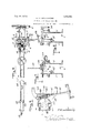
- Figure 2 is a fragmentary view showing more particularly the automatic stop mechanism at opposite ends of the boom for cooperation with the driving gearing to render the latter inactive at proper times.
- Figure 3 is a view looking toward the delivery or discharge end of the mixer and bringing out more clearly the controlling lever and clutch shifting mechanism and adjacent driving mechanism above the inner end of the boom.
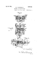
- Figure 4 is a vertical sectional view through the boom and looking toward the outer side of the bucket, bringing out-more fully the mounting of the carriage on the boom and bucket-door closing device.
- Figure 5 is a plan View showing primarily the parts illustrated in Fig. 1, the bucket and certain of the parts beneath the boom being omitted.
- Figure 6 is a plan viewbringing out clearly the worm and worm gear turning devic as improved, also the bumper co-operative with the carriage to limit the inward movement of the bucket on the boom.
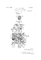
- Figure 7 is a vertical sectional view taken about on the line 7 7 of Fig. 2.
- Figure 8 is a similar section taken about on the line 88 of Fig. 2.
- Figure 9 is a vertical section taken through a portion of the carriage showing the shuttle or slide of the tripping device.
- Figure 10 is a plan view of the same including a trip member.
- Figure 11 is a section on the line 11-11 of Fig. 10.
- Figure 12 is a front view showing more clearly the winding drum of the driving mechanism.
- Figure 13 is an enlarged view showing more clearly the adjustable stop on the carriage.
- Figure 1 1 is a perspective view showing more clearly the arrangement of the lever arms and links of the clutch shifting and knock-out devices.
- A denotes the portion of the mixing drum of the mixing machine illustrated in conjunction with the boom and bucket mechanism
- B the frame work of said machine
- G the toothed gear rings carried by said drum A and by which it is rotatably operated in a Well known manner.
- the boom and bucket mechanism embodies as its primary features the boom 1 and the bucket 2, the latter spaced from the ground, power operated, and being normally non-discharging'in its body construction.
- the driving mechanism by means of which the bucket is caused to traverse the boom 1 comprises a pair of shafts 3 and 4 having pinions at one end meshing with the gear-ring C of the drum A whereby motion at opposite ends large bevel gears 10 with which the gears 5 and 6' mesh.
- the opposite ends 11 and 11 of an operating cable 11 wind around the drum 9 in opposite directions, and have the extremities thereof fixedly attached to the drum as shown best in Fig.12 of the drawings.
- the said cable 11 extends from the end portion 11 down under a show e journaled on top of the boom 1 thence outwardly along the boom around a sheave '13 at the outer extremity of said boom.
- the cable 11 is trained inwardly along the boom adjacent to its under side, said cable passing thence upwardly over a sheave 1 1 located adjacent to the point of pivotal support of the boom 1.
- the cable 11 has its end 11 connected with the drum 9 in the manner previously suggested.
- the sheaves 12 and 14; are located so that the portions of the cable 11 passing over the same are substantially in vertical alinement with the axis of rotative movement of the boom 1 established by the vertical pivot 15. nects the boom with the bracket 16 projecting from theframe B of the machine, said bracket forming the main support interme diate the boom and the frame work of the mixer.
- a rocker lever 17 (see Figs. 3 and 5) is employed, the same being equipped with shifting forks and being mounted upon a vertical shaft 18, seen best in Fig. 3.
- the shaft 18'l1a s a main. hand lever 19 connected with its lower end and this lever is operable to alternately render the clutches 7 and 8active for ellecting reverse movements of the drum 9 and cable 11 or to maintain the clutches 7 and 8 in neutral positions.
- the reverse operation of the drum 9 is effective to cause reverse movement of the bucket 2 relative to the boom 1 by interconnections between the cable 11 and the carriage 20, which interconnections are very
- the pivot 15 conllO the carriage 20 is'best shown in Figs. 9 to 11.
- I provide on the carriage 20, slidable in suitable ways or grooves 23 at opposite sides of the latter, a'
- the slide or shuttle 24 has end bars with openings 25 through which the cable' 11 passes and mounted on the shuttle member 24 is a trip .26 pivoted at 27 and having an upwardly extending arm 28.
- a slack take-up shaft 29 equipped with ratchet wheels 30 and about which the cable 11 is wound so as to extend from the shaft in opposite directions. It will be evident that by turning the shaft 29' by the application of any suitable tool, any unnecessary slack in the length of the cable 11 may be taken up.
- the design of, my bucket 2 and the openable door'34 is especially novel and'importent.
- the door 34 is of a len h corres 0nding to the width of the hue et 2, an said door 1s variably limited in its opening movement by means of an adjustable stop 39 which is attached to one side of the carriage 20 and adjustable lengthwise of said carriage with the arm 32 to limit the movement of said arm in the direction of the mixer, as the arm is shifted to throw over action of the arms 38 under the influence of the trip 26. That is to say, the door 34 can open just so far as is determined by the movement of the arm 32 in the action of trip ing the door 34 to effect said opening.
- t is the adjustability of the stop 39 which admits of the flowing of the concrete aggregates from the bucket 2 in a ribbon-like stream, the thickness of which de nds u n the extent of opening of said oor, an
- the stop co-acts' retarded egress of the aggregates because of the restriction of the door opening.
- the thickness of the stream of materials discharged from the bucket 2 determines the depth of the layer of concrete or aggregates dispensed, so to speak, by the bucket.
- the bucket opening and door 34 are advantageously arranged transversely of the boom, and of the direction of travel of the bucket 2, for theattainment of the above result of depositing the plastic aggregates in a layer of measured thickness.
- the bucket 2 is designedly a low discharge bucket; in other words, the discharge end of the bucket is very near the ground so as to admit of the laying down of the concrete in a relatively thinribbon-like gravitating stream of a width'equal to the width of the bucket and of a depth regulated by adjustment of the stop 39 controlling the operative area-of the opening made by release of the door as the latter drops to its effective opening position.
- the boom 1 is adapted to be raised and lowered byvertical movement of an axis established by the horizontal pivot 40. connecting the boom with the vertical pivot 15 on the bracket 16.
- the means utilized for this purpose are like those heretofore proposed including a cable 41 attached to the upper frame work B of the machine v(see Fig. 1) passing around a sheave 42 on'the boom 1 intermediate theends of the latter, thence passing up and around another sheave 43 on the frame work sections, down again around a second sheave42, co-axial-with the previous sheave 42, and thereafter passing to awindlass device shown at 44 as mounted on the boom 1 adjacent to the inner end of theboom.
- v a cable 41 attached to the upper frame work B of the machine v(see Fig. 1) passing around a sheave 42 on'the boom 1 intermediate theends of the latter, thence passing up and around another sheave 43 on the frame work sections, down again around a second sheave42, co-axial-with the previous sheave 42
- the means for turning the boom 1 by'movement in a hor-' izontal plane said means involving generally the previousl well known worm gear sector fixed on t e pivot 15 by which the boom is sup-ported for said horizontal movement.
- This worm gear is engaged by a worm 56 on-the manually rotatable shaft 57 adapted to be turned by the wheel 58.
- the Worm 56 may be said to be a floating worm to the extent that it is movable endwise on the shaft 57, though of course, splined are interposed between said boxes 59.
- the initial action of the worm 56 is to yield by compression of one of the springs 60, the one, in the direction opposite that in which the boom will turn. After slight compressionof said spring, the boom will begin. to swing and the worm will becomecentralized. between the boxes 59 under-v the action of the springs.
- said worm 56 On stop age of the turning movement of the shaft 5 if there is contmued movement of the boom under the'impetus of its swing produced by manual o eration of the wheel 58, said worm 56 "will yield longitudinally on the shaft 57 andthere will. be no-tendenc 55 and 56 to becomelocked by the friction incident to. the. action of theworm 56 as a stop for. limiting the movement or swinging of the boom.
- the -,worm gear 55 a yieldable bumper 61 with which the carriage 20 may abut as it for the parts reaches the inward limit of its movement in traversing the boom 1.
- the bumper includes a plate 61, and two springs 61 interposed between said plate and two pivot lugs 55 on the gear 55. It will be evident that this bumper 61 affords a resilient means, intermediate the bracket 16 and the carriage by which the bracket'2 is supported to absorb the shock incident to abutment between the above .parts as the bucket reaches its charging position. adjacent to the mixer.
- I utilize linkage 35 and a spring 36 cooperative with the curved link 37 and arms 38 to connect the trip mechanism with the bottom doors 34: of the bucket 2.
- the .lever 50 controlling the reversing or clutch neutralizing action previously described is adapted to perform an additional function to that of rendering the clutch 8 ineffective;
- the operation of this lever to turn the shaft 18 is adapted to turn an arm 62 just above the arm 52 of the shaft 18.
- the arm 62 is connected by links 63 with the toggle lever 64.- interposed between a bracket 65,
- the automatic braking means for retarding the movement of the bucket as above described is particularly useful Where the )machine is disposed upgn .a grade which requires that the boom elevated so as to incline upwardly and-. outwardly from the mixer, bearing in mind the size and'welght er drum A into said bucket.
- some braking means is very desirable to govern the inward movement of the bucket, both when the boom is adjusted in a horizontal plane, and especially when it is disposed in an inclined position as described.
- the bucket 2 is filled by the customary discharging of a predetermined quantity of concrete or mixed aggregates from the mix-
- the aggregates are now ready to be distributed or laid upon the sub-grade for which purpose the operator will manually actuate the lever 19 to throw into operation the clutch mechanism whereby to drive the drum 9 in the direction to effect an out-haul movement of the lower bight of the cable.
- the initial out-haul movement causes the trip member 26 to assume an operative position on the outer sideof the upper end of the arms 38 and continued out-haul movement causes the carriage 20 and the bucket 2 to traverse the boom 1 until the operator reverses the movement of the cable 11 by proper control of the clutch mechanism.
- the trip member 26 On reversing the movement of the cable 11 the slide or shuttle member 24 moves in the direction of the inner end of the boom, the trip member 26 actuates the throw-over arms 38, rocks the shaft 33 and releases or opens the door 34; of the bucket.
- the mixed aggregates in the bucket are in a free flowing state and the reversing of the cablemovement is intended not only to efiect opening of the door 34, but also immediate return traverse of the bucket 2 relative to the boom 1.
- the combination of the door opening and the return traverse movement of the bucket 2 are important to my invention because such actions together are efiective to stream the a gregates from thebucket 2 in a ribbonli e layer of substantially rectangular crosssection as previously described, the thickness or depth .of which layer is controlled by the stop 39.
- the cam 31 engages the cross-arm 32, restores the throw-over arms 38 to their elevated bucket door closing positions, and automatic stopping of the carriage 20 and. bucket 2 1s efiected through the action of the clutch knock-out mechanism hereinbefore described.
- the method which I practice in the actual operation 'of my machine is the conveying or conducting of the aggregates mixed in the mixer to the site of deposit, by the distributmg element or bucket of course, and then while the aggregates in their plastic condition are in movement they are caused to flow gravitatively from the bucket in a continuous stream of'a redetermined depth or thickness substantially equal to that of the slab or portion of pavement of which the particular batch of the aggregates will ultimately form a part.
- laborious work in spreading the materials is saved. This is a novel method of my invention.
- a boom and bucket attachment for concrete mixers having in combi nation, a support, a boom mounted to swing horizontally thereon, a carriage adapted to traverse said boom lengthwise thereof in opposite directions, a concrete distributor bucket mounted on said carriage, the bucket comprising dumping means for emptying it of its contents, tri mechanism on the carriage for contro ing the said dumping mechanism, cable apparatus iated wit brake means on both the outwar a part of the cable apparatus to operation of the bucket.
- the boom and trip mechanism and carriage so as to control the movement of the carriage on the boom and the operation of the trip mechanism for dumping the bucket, and automatic brake mechanism mounted on the'support carrying the boom and oper-- atively connected with a part of the cable apparatus aforesaid, to retard the movement of the latter and thereby control its action in relation to the carriage.
- a boom and bucket attachment for concrete mixers having in combination, a support, a boom mounted to swing horizontally thereon, a carriage adapted to traverse said boom lengthwise thereof in opposite directions, a concrete distributor bucket mounted on said carriage, the bucket comprising dumping means for emptying it of its contents, trip mechanism on the carriage for controlling the said dumping mechanism, cable apparatus associatedwith the boom and trip mechanism and carriage so as to control the movement of the carriage on the boom and the operation of the trip mechanism for dumpln 1 the bucket, and a brake mechanism mounte upon the support on which the boom is mounted and operatively connected with a part of the cable apparatus, together with means forautomatically appliying said and inward movements of the bucket along the boom. 1 n 3.
- a boom and bucket attachment for concrete mixers the combination of a support, a boom pivotally mounted-upon said support to swing horizontally, a bucket adapted to travel inwardly and outwardly upon and suspended from the boom, said bucket comprising dumping means there for, cable ap aratus for controlling the movement of the bucket and the tripping of its dumping mechanism, and an automatically operable brake means cooperative with control the 4.
- a boom and bucket attachment for concrete mixers the combination of a support, a boom pivotally mounted uponsaid support to swing horizontally, a bucket adapted to travel inwardly and outwardly upon and suspended from the boom, said bucket comprising dumping means there for, cable apparatus for controlling the movement of the bucket and the tripping of its dumpingmechanism, and an automatically operable brake means cooperative with a art of the cable apparatus to retard the hue et in its movement in opposite directions relative to the boom.
- Means as claimed in claim 7 combined with a carriage which supports the bucket on the boom, and which supports the driving connection between the cable means and said bucket, said driving connection comprising a winding member constituting said slack take-up device, and a shuttle member, a trip art connected with the shuttle member, a ischarge. door for the bucket and discharge door operating means on the carriagte adapted to be actuated by said trip par c 9.
- a boom a bucket ada ted to travel longitudinally on the boom ack and forth, cable apparatus cooperative with the bucket in its back and forth movement
- the bucket comprising dumping mechanism, tripping mechanism arranged to co-act with said dumpingmechanism to operate the latter thru the cooperation of the cable apparatus with said tripping mechanism, and an .operative connection between the tri ping mechanism and the portion of the cab e a" aratus that co-a'cts therewith to dump t e ucket, including a cable tension take-up device.
- a support a boom mounted to swing. horizontally fill thereon, a bucket arranged to move back and forth along the boom to carry concrete from a'mixer to a point of deposit in the length of the boom, a carriage on the boom supporting said bucket for its said movement, the bucket comprising a dumping means therefor, trip mechanism on the carriage connected with said dumpin means for shifting the latter to and from umping positions,'cable apparatus controlling the operation of said tripping mechanism, and means operatively connecting the cable apparatus with the tripping mechanism, including cable tension take-up instrumentalities.
- a boom a carriage arranged to move back and forth on the boom, a bucket supported b said carriage, cable controlling means for t e carriage, and 'a take-up connection intermediate said cable means and the carriage including a winding shaft mounted on .the carriage and about which the cable is adapted to be wound in order to take up slack.
- a boom In a concrete distributor of the boom and bucket type, a boom, a carriage slidable back and forth on the boom', a bucket supported by the-carriage, a cable for moving the bucket back and forth and a connection intermediate the cable and the carriage including a shaft mounted on the carriage and adapted to be rotated, and connecting means between the shaft and portions of the cable whereby the cable may be wound about the shaft to take up slack in the cable.
- a support adapted to swing horizontally thereon, a carriage adapted to move back and forth on the boom, a bucket suspended' from the carriage and comprising dumping means, tripping mechanism on the carriage for said dum mg means to render it operative and inoperative and including a knockover link shiftable from a position maintaining the dumping mechanism'inoperative, to one rendering it operative, and vice versa, cable apparatus cooperative with the tripping mechanism and includedin a cable part having connection with the %atter, the said connection involving cable tension take-up instrumentalities.
- a boom and bucket concrete distributor the combination with a boom adapted to swing horizontally, a carriage adapted to travel back and forth on the boom, a bucket supported by said carriage and having dumping means at its bottom portion, trlp mechanism on the carriage including a shaft, a curved link operativelyv connected with said shaft to be raised and lowered thereby, a cross plate adjacent to the lower end of said link, a bolt passing through the lower portion of said link and through saidcross plate, a s ring beneath the cross plate and surroun ing said bolt and hearing at one end against the cross plate and having a hearing at its opposite 7 end against the lower end of the bolt, linkage between the op osite ends of the cross plate at opposite s1 es of said bolt and havmg connection with the dumping means of the bucket, and means for tripping the trip mechanism to lower said curved. link and raise it, the dumpin means becoming operative when the lin is lowered and inoperative when the link-is raised.
- a concrete distributor in combination with a boom, a distributing bucket, a carriage movable back and forth on the boom to carry said bucket, trip mechanism on the carriage including a curved knockover link, the bucket having dumping means at its bottom, a cross plate, linkage connecting the ends of said cross plate with the dumping means of the bucket and a resilient connection intermediate said knockover member and said cross plate as and for the purpose described, the knock-over member being adapted to be raised and lowered by the trip mechanism to maintain the dumping means of the bucket closed and open respectively.
- bracket device includes a worm gear appliance for swinging the 00m, and resilient bufier means intermediate the carriage and one of said bracket devices.
- bracket device including a worm gear appliance for swinging the boom, resilient bufi'er means intermediate the carriage and one of said bracket devices and comprising springs adapted to absorb the shock between the carriage and said bracket device as the carriage reaches the end of the boom supported by the bracket device.
- bracket device mounted on said frame-work to support the boom and to which the boom is pivotally connected, another bracket device including a worm gear appliance for swinging the boom, resilient bufi'er means intermediate the carriage and one of said bracket devices and comprising springs carried by parts of the-bracket device above mentioned, and adapted to be compressed by cooperation with the carriage as the latter reaches the end of the directly cooperating with said cable means for braking the movement of the carriage as it operates on the boom.
- a boom and bucket concrete distributor in combination, a boom, a carriage to traverse the boom, a bucket supported by the carriage, cable meansfor moving the carriage on the boom, brake means directly cooperating with said cable means for braking the movement of the carriage as it opcrates on the boom and manual and automatic devices to control the action of said brake means.
Landscapes
- Engineering & Computer Science (AREA)
- Architecture (AREA)
- Civil Engineering (AREA)
- Structural Engineering (AREA)
- Shovels (AREA)
Description
July 14, 1925 E. H. LICHTENBERG CONCRETE DI STRIBUTING MACHINE Original Filed July 19, 1920 s'sheetssheet 1 July 14, 1925.
E. H. LICHTENBERG CONCRETE DISTRIBUTING MACHINE Original Filed July 19, 1920 5 Sheets-Sheet 2 3n neuron Jui 14, W25.
E. H. LICHTENBERG CONCRETE DISTRIBUTING MACHINE Original Filed July 19, 5 Sheets-Sheet Ill!ll'lllllillfllllllllllll'lilflfll l llljlill 15* July 14, 1925.
1,5462 92 E. H. LICHTENBERG CONCRETE DISTR IBUTING MACHINE Original Filed July '19, 1920 5 Sheets-Sheet 4 $2333] 14, i 925. E. HY LICHTENBERG CONCRETE DISTRIBUTING MACHINE Original Filed July 19, 1920 5 h e heet 5 Patented at; 14, 1925 UNITED STATES 1,546,292 PATENT OFFlCE.
ERICK H. LIGHTENZBEBG, O'F-MEWAUKEE, WISCONSIN. ASSIGNOR TC KOEEBING COI- PANY, OF MILWAUKEE, -WISCONSITN, A CORPORATION.
coNcanrn-ms'rmau'rme momma Original application filed July 19; 1920, Serial No. 897,431. Patent-No. 1,411,217,- dated Iaroh- B8, 1998.
' Divided and this application filed Hatch 24, 1922. Serial No'. 546,278,
To an wiwm it may concern:
Be it known that I, ERIGH H. Llcn'inn- BERG, a citizen of the United States, residing at Milwaukee, in the county of M1l-' c waukee and State of 'Wisconsin, have in:
vented certain new and useful Improvements in Concrete-DistributingMachines, of
which the following is. a specification.-
In the art-of laying concrete roads, pavew ments and the like, there is commonly used as the most expeditious and economical method of distributing theconcrete or mixed aggregates of whichthep'avement is. composed, a machinewhich comprises, generally speaking, acombined mixer and boom and bucket distributing means. This machine ordinarily known as the Koehring paver, embodies a portableqplant which includes the concrete mixing and customary 2c appurtenant control ifiechanisms, together with the boom and bucket attachment operated from thesame power as used for the mixing machine and controlled by the same operator. I My present improvements comprlse a d v sion' ofmy c0 endin application for patent Serial No. 3 431, ed July 19, 1920, now matured into Letters Patent No. 1,411,217 issued March 28, 1922, and among the principal objects of said improvements are the simplifying of the driv ng mechanism utilized for causing the bucket to traverse "the 'boom by which the distributionof the concrete over a relatively large area may be performed; the provisionof a'more positive driving mechanism for the pn e just outlined; and the improvement 0 certain knock-out or clutch neutralizing devices, certain of which have been heretofore roployed in conjunction with the'drivi devices for the. bucket mechanism, where y it 6 the machine is operating in a 'onwherein the boom is inclined upwar 1y, the inward and downward ,vmfivement of-the bucket; may be retarded unlit approaches posed by me for automatically (llSGOIltlIlll- 'portin ments resides in special braking means em the mixer end of the boom through the action of automatic braking mechanism.
grade. This feature of my invention isof importance and involves the worm and worm gear contrivances originally proposedin the Letters Patent Reissue No. 13,617,, issued September 16, 1913, to Phili Koehring, said patent covering the basic machine improved by the features of my Letters Patent No, 1,141,470 and. No. 1,113,-
661 issued June 1, 1915 and ()ctober13,
1914 respectively. [In the operation of the worm and worm gear boom turning means,
there has been a tendency heretofore to cause locking of the'png worm gear contrivances, owmgf to'the mbmentum 'of the boom oncefthe horizontal movement 1s imparted thereto. I merely mount my worm in a resilient manner as regards end-wise movement, in respect to the engaged worm r, and in this way eliminate the possibi ity of the disadvantathe same time rendering more easy the operin respect to initiating as well as stopping said boom movement. I a
The present invention furthermore involves a novel improved connection intermediate the trip mechanism on the carriage. and the doors of the bucket, the said connection involving resiliently acting'parts. Additionally th invention involves a new form of resilient bumper means intermedi-r geous locking of the parts as referred to,at
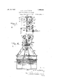
V ation of'theboom by said parts manually ate theoarriage and the bracket means supthe boom swinging worm'gear. A' 1111 comprehension of the-improvements of this invention will be had upon an understanding of the machinesof the Let- 'ters Patent previously set forth herein'fin connection withthe followingdescription" and theaccompanying drawings in which .105 Figure 1 is a side view showingparticu larly the boom and bucket attachment as designed with the present improvements, dotted lines indicating in a general way the adjacent end portion of the mixing machine upon which the boom and bucket mechanism is mounted.
Figure 2 is a fragmentary view showing more particularly the automatic stop mechanism at opposite ends of the boom for cooperation with the driving gearing to render the latter inactive at proper times. Figure 3 is a view looking toward the delivery or discharge end of the mixer and bringing out more clearly the controlling lever and clutch shifting mechanism and adjacent driving mechanism above the inner end of the boom.
Figure 4; is a vertical sectional view through the boom and looking toward the outer side of the bucket, bringing out-more fully the mounting of the carriage on the boom and bucket-door closing device.
Figure 5 is a plan View showing primarily the parts illustrated in Fig. 1, the bucket and certain of the parts beneath the boom being omitted. v
Figure 6 is a plan viewbringing out clearly the worm and worm gear turning devic as improved, also the bumper co-operative with the carriage to limit the inward movement of the bucket on the boom. I
Figure 7 is a vertical sectional view taken about on the line 7 7 of Fig. 2.
Figure 8 is a similar section taken about on the line 88 of Fig. 2.
Figure 9 is a vertical section taken through a portion of the carriage showing the shuttle or slide of the tripping device.
Figure 10 is a plan view of the same including a trip member.
Figure 11 is a section on the line 11-11 of Fig. 10.
Figure 12 is a front view showing more clearly the winding drum of the driving mechanism.
Figure 13 is an enlarged view showing more clearly the adjustable stop on the carriage; and
Figure 1 1 is a perspective view showing more clearly the arrangement of the lever arms and links of the clutch shifting and knock-out devices.
Referring to the drawings in which the same reference characters are used to designate corresponding parts in difierent views, and describing the improvements thereof in detail, A denotes the portion of the mixing drum of the mixing machine illustrated in conjunction with the boom and bucket mechanism, B the frame work of said machine, and G the toothed gear rings carried by said drum A and by which it is rotatably operated in a Well known manner. The boom and bucket mechanism embodies as its primary features the boom 1 and the bucket 2, the latter spaced from the ground, power operated, and being normally non-discharging'in its body construction.
The driving mechanism by means of which the bucket is caused to traverse the boom 1 comprises a pair of shafts 3 and 4 having pinions at one end meshing with the gear-ring C of the drum A whereby motion at opposite ends large bevel gears 10 with which the gears 5 and 6' mesh. The opposite ends 11 and 11 of an operating cable 11 wind around the drum 9 in opposite directions, and have the extremities thereof fixedly attached to the drum as shown best in Fig.12 of the drawings. The said cable 11 extends from the end portion 11 down under a show e journaled on top of the boom 1 thence outwardly along the boom around a sheave '13 at the outer extremity of said boom. From the sheave 13 the cable 11 is trained inwardly along the boom adjacent to its under side, said cable passing thence upwardly over a sheave 1 1 located adjacent to the point of pivotal support of the boom 1. At this point the cable 11 has its end 11 connected with the drum 9 in the manner previously suggested. The sheaves 12 and 14; are located so that the portions of the cable 11 passing over the same are substantially in vertical alinement with the axis of rotative movement of the boom 1 established by the vertical pivot 15. nects the boom with the bracket 16 projecting from theframe B of the machine, said bracket forming the main support interme diate the boom and the frame work of the mixer.
To operate the clutches 7 and 8 a rocker lever 17 (see Figs. 3 and 5) is employed, the same being equipped with shifting forks and being mounted upon a vertical shaft 18, seen best in Fig. 3. The shaft 18'l1as a main. hand lever 19 connected with its lower end and this lever is operable to alternately render the clutches 7 and 8active for ellecting reverse movements of the drum 9 and cable 11 or to maintain the clutches 7 and 8 in neutral positions. a
The reverse operation of the drum 9 is effective to cause reverse movement of the bucket 2 relative to the boom 1 by interconnections between the cable 11 and the carriage 20, which interconnections are very The pivot 15 conllO the carriage 20 is'best shown in Figs. 9 to 11. For the above purpose Iprovide on the carriage 20, slidable in suitable ways or grooves 23 at opposite sides of the latter, a'
slide or shuttle 24. The slide or shuttle 24 has end bars with openings 25 through which the cable' 11 passes and mounted on the shuttle member 24 is a trip .26 pivoted at 27 and having an upwardly extending arm 28. Centrally of the slide or shuttle 24 there is mounted'a slack take-up shaft 29 equipped with ratchet wheels 30 and about which the cable 11 is wound so as to extend from the shaft in opposite directions. It will be evident that by turning the shaft 29' by the application of any suitable tool, any unnecessary slack in the length of the cable 11 may be taken up.
The action of the trip 26 is very similar to the action of certain corresponding trip mechanism of my previous Patent No. 1,141,470, and will be generally set forth hereinafter. Y a
Reverse movement of the cable 11 imparts corresponding movement to the carriage 20, and said carriage supports the bucket 2 for a corresponding movement of the latter. I utilize my previously invented and well known cam 31 toco-opera'te with an "arm 32 on the shaft 33 for the urpose of closing the bottom door 34 o the bucket 2. The bottom door 34 is connected by linkage 35 and spring 36 with the curved'link 37 which in turn is attached to the throw .over arms 38 projecting from the shaft 33 all substantially as disclosed in my. last named Letters Patent. j
' The design of, my bucket 2 and the openable door'34 is especially novel and'importent. The door 34 is of a len h corres 0nding to the width of the hue et 2, an said door 1s variably limited in its opening movement by means of an adjustable stop 39 which is attached to one side of the carriage 20 and adjustable lengthwise of said carriage with the arm 32 to limit the movement of said arm in the direction of the mixer, as the arm is shifted to throw over action of the arms 38 under the influence of the trip 26. That is to say, the door 34 can open just so far as is determined by the movement of the arm 32 in the action of trip ing the door 34 to effect said opening. t is the adjustability of the stop 39 which admits of the flowing of the concrete aggregates from the bucket 2 in a ribbon-like stream, the thickness of which de nds u n the extent of opening of said oor, an
by means of a suitable bolt passing, through the said stop. The stop co-acts' retarded egress of the aggregates because of the restriction of the door opening. Necessarily the thickness of the stream of materials discharged from the bucket 2 determines the depth of the layer of concrete or aggregates dispensed, so to speak, by the bucket. The bucket opening and door 34 are advantageously arranged transversely of the boom, and of the direction of travel of the bucket 2, for theattainment of the above result of depositing the plastic aggregates in a layer of measured thickness.
The bucket 2 is designedly a low discharge bucket; in other words, the discharge end of the bucket is very near the ground so as to admit of the laying down of the concrete in a relatively thinribbon-like gravitating stream of a width'equal to the width of the bucket and of a depth regulated by adjustment of the stop 39 controlling the operative area-of the opening made by release of the door as the latter drops to its effective opening position.
The boom 1 is adapted to be raised and lowered byvertical movement of an axis established by the horizontal pivot 40. connecting the boom with the vertical pivot 15 on the bracket 16. The means utilized for this purpose are like those heretofore proposed including a cable 41 attached to the upper frame work B of the machine v(see Fig. 1) passing around a sheave 42 on'the boom 1 intermediate theends of the latter, thence passing up and around another sheave 43 on the frame work sections, down again around a second sheave42, co-axial-with the previous sheave 42, and thereafter passing to awindlass device shown at 44 as mounted on the boom 1 adjacent to the inner end of theboom. v
On the boom 1 there is provided certain automaticall operating clutch knock-out mechanism or the clutches 7 and 8. This mechanism is seenbest in Figsr2 and 3 of the drawings. In the outward traverse of the carriage" 20 with the bucket 2, if the operator does not reverse themovement of the cable 11 by manual control of the clutches through the lever 19, said carriage will strike the knock-out or shifter arm 45 located adjacent to the outer end of the boom and pivoted to a bracket 46 thereon. The arm 45 is equipped with'a pull rod 47 extending longitudinally of the boom intermediate the channels thereof. .Whenthe knock-out or shifter arm 45 is rocked upward'a pull is exerted on the rod 47 and said rod actuates a bell crank lever 48 near the inner end of the boom in such a manner as to pull downwardly upon a bar 49 which is attached to another bell crank lever 50 which is pivoted at 51 on theframe work B. The vertical arm or lever 50 is connected with a horizontal arm 52 and olfstanding due to from the shaft 18 which it will be recalled is 4'0, thereto to turn therewith; The worm op- .era-te's between boxes 59 in which the shaft 57 isjournaled on the bracket 16 and springs lever 45. On inward movement of the car riage 20, in order to automatically neutralize or render ineffective the one of the clutches 7 or 8 which is employed to cause return movement of the carriage upon the boom, there is provided a cam 53, seen best in Fig. 2, and this cam is adapted to ride beneath the roller 54 on the bottom of the bar 49, thereby raising said bar and effecting the operation of knock-out of the effective clutch by which the return movement of the carriage and bucket is being caused. Thisaction will be obvious with the previous deseription of the clutch neutralizing operation from the knock-out member 4:5 and-the principle of operation is quite similar to that found in my Letters Patent No. 1,113,661 previously referred to.
There isleft to be describedthe means for turning the boom 1 by'movement in a hor-' izontal plane, said means involving generally the previousl well known worm gear sector fixed on t e pivot 15 by which the boom is sup-ported for said horizontal movement. This worm gear is engaged by a worm 56 on-the manually rotatable shaft 57 adapted to be turned by the wheel 58. The Worm 56 may be said to be a floating worm to the extent that it is movable endwise on the shaft 57, though of course, splined are interposed between said boxes 59. On turning the shaft 57 to swing the boom 1 horizontally, the initial action of the worm 56 is to yield by compression of one of the springs 60, the one, in the direction opposite that in which the boom will turn. After slight compressionof said spring, the boom will begin. to swing and the worm will becomecentralized. between the boxes 59 under-v the action of the springs. On stop age of the turning movement of the shaft 5 if there is contmued movement of the boom under the'impetus of its swing produced by manual o eration of the wheel 58, said worm 56 "will yield longitudinally on the shaft 57 andthere will. be no-tendenc 55 and 56 to becomelocked by the friction incident to. the. action of theworm 56 as a stop for. limiting the movement or swinging of the boom. There is mounted .upon.
the -,worm gear 55 a yieldable bumper 61 with which the carriage 20 may abut as it for the parts reaches the inward limit of its movement in traversing the boom 1. The bumper includes a plate 61, and two springs 61 interposed between said plate and two pivot lugs 55 on the gear 55. It will be evident that this bumper 61 affords a resilient means, intermediate the bracket 16 and the carriage by which the bracket'2 is supported to absorb the shock incident to abutment between the above .parts as the bucket reaches its charging position. adjacent to the mixer. As previously described, I utilize linkage 35 and a spring 36 cooperative with the curved link 37 and arms 38 to connect the trip mechanism with the bottom doors 34: of the bucket 2. The specific mode ofconnection of these parts is novel in that I use a cross plate 37 through which passes the bolt 37 that is encircled by the spring 36', previously mentioned. The curved link 37- is so arranged that the bolt 37 lower end as seen in Figure 1. The upper link members of the linkage 35 pass through the opposite ends of the plate37 and the spring 36 bears upwardlyagainst the intermediate portion of said plate 37 from beneath. The parts 35 and'36, 37 and 37 virtually form a resilient connection between the arms'38 and the doors, so that if any foreign matter should lodge between the doors 34 and the body of the bucket 2 no breakage will result in the said connecting means.
It is furthermore notable that the .lever 50 controlling the reversing or clutch neutralizing action previously described is adapted to perform an additional function to that of rendering the clutch 8 ineffective; The operation of this lever to turn the shaft 18 is adapted to turn an arm 62 just above the arm 52 of the shaft 18. The arm 62 is connected by links 63 with the toggle lever 64.- interposed between a bracket 65,
on the frame work, and the free end of a brake band 66 which partially encircles the clutch member 8, co-operateswith the clutch 8. Thus it is that through the operation of the automaticv clutch knock-out mechanism acting on the lever 50 or by the control of the shaft 18 through the hand lever 19 previously described, the parts 62, 63 and 66may be operated to apply a brake to the clutch 8 and thus brake the operation of the pinion 6 operating the adjacent drum 9. In this way quick reduction of the movement of the drum and corresponding passes through its stoppage of the movement of the bucket outwardly and inwardly is controlled.
The automatic braking means for retarding the movement of the bucket as above described, is particularly useful Where the )machine is disposed upgn .a grade which requires that the boom elevated so as to incline upwardly and-. outwardly from the mixer, bearing in mind the size and'welght er drum A into said bucket.
of the bucket, it will be evident that some braking means is very desirable to govern the inward movement of the bucket, both when the boom is adjusted in a horizontal plane, and especially when it is disposed in an inclined position as described.
The general operation of my machine according tothe design hereinbefore described is as follows:
The bucket 2 is filled by the customary discharging of a predetermined quantity of concrete or mixed aggregates from the mix- The aggregates are now ready to be distributed or laid upon the sub-grade for which purpose the operator will manually actuate the lever 19 to throw into operation the clutch mechanism whereby to drive the drum 9 in the direction to effect an out-haul movement of the lower bight of the cable. The initial out-haul movement causes the trip member 26 to assume an operative position on the outer sideof the upper end of the arms 38 and continued out-haul movement causes the carriage 20 and the bucket 2 to traverse the boom 1 until the operator reverses the movement of the cable 11 by proper control of the clutch mechanism. On reversing the movement of the cable 11 the slide or shuttle member 24 moves in the direction of the inner end of the boom, the trip member 26 actuates the throw-over arms 38, rocks the shaft 33 and releases or opens the door 34; of the bucket. The mixed aggregates in the bucket are in a free flowing state and the reversing of the cablemovement is intended not only to efiect opening of the door 34, but also immediate return traverse of the bucket 2 relative to the boom 1. The combination of the door opening and the return traverse movement of the bucket 2 are important to my invention because such actions together are efiective to stream the a gregates from thebucket 2 in a ribbonli e layer of substantially rectangular crosssection as previously described, the thickness or depth .of which layer is controlled by the stop 39. As the bucket 2 returns to its position adjacent to the mixer and at the inner end of the boom 1, the cam 31 engages the cross-arm 32, restores the throw-over arms 38 to their elevated bucket door closing positions, and automatic stopping of the carriage 20 and. bucket 2 1s efiected through the action of the clutch knock-out mechanism hereinbefore described.
If the operator fails to cause a reverse movement of the cable 11 by operation of the lever 19 manually the efiective action of the bucket discharge will begin to take place as the bucket reaches the outer end 0 the boom. This will be erformed automatically through the carriage 20 abutting with and operating the knock-out or shifter arm 45 of the clutch mechanism controlling the drive means. Furthermore, the operation of the arm 45 will be such as not only to render inactive the clutch controlling the out-haul movement of the cable, but to render active the clutch which embodies the in-haul movement of said cable whereby the movement of the bucket 2 will be actually reversed so as to insure the laying of the concrete by streaming of the same out of the bucket 2 in the manner above set forth. The method which I practice in the actual operation 'of my machine is the conveying or conducting of the aggregates mixed in the mixer to the site of deposit, by the distributmg element or bucket of course, and then while the aggregates in their plastic condition are in movement they are caused to flow gravitatively from the bucket in a continuous stream of'a redetermined depth or thickness substantially equal to that of the slab or portion of pavement of which the particular batch of the aggregates will ultimately form a part. By this method laborious work in spreading the materials is saved. This is a novel method of my invention.
The action of the brake-band 8 is inci= dent to straightening of the links of the toggle lever 64 and takes place on both the in 2aul and outhaul movements of the bucket Whether the operation of the member 45 effects mere neutralizing of the clutch devices requirin the reverse movement of the bucket to be e ected by manual operation, or reversing of the clutch mechanism and inhaul movement bf bucket 2 depends on the adjustment of the arm 45, and the latter is controlled b adjustment of turnbuckle 4:7 in the length of the rod 47, or in any suitable manner.
Of course the dumping and reverse movement of bucket 2 maybe performed at any point in the outward movement of the bucket, as well understood on reference to my precious patents.
It is notable that as the portion. 11 of the cable unwinds from the spiral oove of the drum 9, the portion 11 win s into the vacated part of the groove, and vice versa.
Having thus described my invention, what I claim as new and desire to secure by Letters Patent is: I
1. A boom and bucket attachment for concrete mixers, the same having in combi nation, a support, a boom mounted to swing horizontally thereon, a carriage adapted to traverse said boom lengthwise thereof in opposite directions, a concrete distributor bucket mounted on said carriage, the bucket comprising dumping means for emptying it of its contents, tri mechanism on the carriage for contro ing the said dumping mechanism, cable apparatus iated wit brake means on both the outwar a part of the cable apparatus to operation of the bucket.
the boom and trip mechanism and carriage so as to control the movement of the carriage on the boom and the operation of the trip mechanism for dumping the bucket, and automatic brake mechanism mounted on the'support carrying the boom and oper-- atively connected with a part of the cable apparatus aforesaid, to retard the movement of the latter and thereby control its action in relation to the carriage.
2. A boom and bucket attachment for concrete mixers, the same having in combination, a support, a boom mounted to swing horizontally thereon, a carriage adapted to traverse said boom lengthwise thereof in opposite directions, a concrete distributor bucket mounted on said carriage, the bucket comprising dumping means for emptying it of its contents, trip mechanism on the carriage for controlling the said dumping mechanism, cable apparatus associatedwith the boom and trip mechanism and carriage so as to control the movement of the carriage on the boom and the operation of the trip mechanism for dumpln 1 the bucket, and a brake mechanism mounte upon the support on which the boom is mounted and operatively connected with a part of the cable apparatus, together with means forautomatically appliying said and inward movements of the bucket along the boom. 1 n 3. In a boom and bucket attachment for concrete mixers, the combination of a support, a boom pivotally mounted-upon said support to swing horizontally, a bucket adapted to travel inwardly and outwardly upon and suspended from the boom, said bucket comprising dumping means there for, cable ap aratus for controlling the movement of the bucket and the tripping of its dumping mechanism, and an automatically operable brake means cooperative with control the 4. In a boom and bucket attachment for concrete mixers, the combination of a support, a boom pivotally mounted uponsaid support to swing horizontally, a bucket adapted to travel inwardly and outwardly upon and suspended from the boom, said bucket comprising dumping means there for, cable apparatus for controlling the movement of the bucket and the tripping of its dumpingmechanism, and an automatically operable brake means cooperative with a art of the cable apparatus to retard the hue et in its movement in opposite directions relative to the boom.
5. In a concrete distributing machine, the combination of a boom, a bucket for traversing) movement thereon, means to drive said ucket to and fro on the boom, and means to discontinue the driving action of the driving means in respect to said bucket, I
and to simultaneously brake the movement of the bucket relative to the boom.
6. In' a concrete distributing machine, the combination of a boom, a bucket for traversing said boom back and forth, clutch mechanism, driving mechanism adapted to be connected by said clutch mechanlsm for actuating the bucket, means to render said clutch mechanism inoperative, brake means for retarding the movementof the bucket along the boom, and interacting means between said clutch and brake means. I
7. In a boom and bucket distributor, the combination of a boom, a bucket to traverse the boom, cable driving means for said bucket, and connectin means intermediate the bucket and cable riving means including a slack take-up device for the cable means.
8, Means as claimed in claim 7 combined with a carriage which supports the bucket on the boom, and which supports the driving connection between the cable means and said bucket, said driving connection comprising a winding member constituting said slack take-up device, and a shuttle member, a trip art connected with the shuttle member, a ischarge. door for the bucket and discharge door operating means on the carriagte adapted to be actuated by said trip par c 9. In aboom, and bucket attachment for concrete mixing machines, in combination, a boom, a bucket adapted to travel longitudinally on the boom back and forth, cable apparatus'cooperating with the bucket in its back and fort movement, the bucket comprlsing dumping mechanism, tripping mechanism arranged to coact with said dumping mechanism to operate. the latter thru the cooperation of the cable apparatus with said tripping mechanism, and an operative' connection between .the trip mechanism and'a part of the cable apparatus, including a cable take-up means.
10. In a boom and bucket attachment for concrete mixing machines, in combination,
a boom, a bucket ada ted to travel longitudinally on the boom ack and forth, cable apparatus cooperative with the bucket in its back and forth movement, the bucket comprising dumping mechanism, tripping mechanism arranged to co-act with said dumpingmechanism to operate the latter thru the cooperation of the cable apparatus with said tripping mechanism, and an .operative connection between the tri ping mechanism and the portion of the cab e a" aratus that co-a'cts therewith to dump t e ucket, including a cable tension take-up device.
11. In a boom and bucket attachment for concrete mixers, in combination, a support, a boom mounted to swing. horizontally fill thereon, a bucket arranged to move back and forth along the boom to carry concrete from a'mixer to a point of deposit in the length of the boom, a carriage on the boom supporting said bucket for its said movement, the bucket comprising a dumping means therefor, trip mechanism on the carriage connected with said dumpin means for shifting the latter to and from umping positions,'cable apparatus controlling the operation of said tripping mechanism, and means operatively connecting the cable apparatus with the tripping mechanism, including cable tension take-up instrumentalities.
12. In a machine of the class described, in combination, a boom, a carriage arranged to move back and forth on the boom, a bucket supported b said carriage, cable controlling means for t e carriage, and 'a take-up connection intermediate said cable means and the carriage including a winding shaft mounted on .the carriage and about which the cable is adapted to be wound in order to take up slack.
13. In a concrete distributor of the boom and bucket type, a boom, a carriage slidable back and forth on the boom', a bucket supported by the-carriage, a cable for moving the bucket back and forth and a connection intermediate the cable and the carriage including a shaft mounted on the carriage and adapted to be rotated, and connecting means between the shaft and portions of the cable whereby the cable may be wound about the shaft to take up slack in the cable.
14. In aboom and bucket attachment for concrete mixers, in combination, a support, a boom adapted to swing horizontally thereon, a carriage adapted to move back and forth on the boom, a bucket suspended' from the carriage and comprising dumping means, tripping mechanism on the carriage for said dum mg means to render it operative and inoperative and including a knockover link shiftable from a position maintaining the dumping mechanism'inoperative, to one rendering it operative, and vice versa, cable apparatus cooperative with the tripping mechanism and includin a cable part having connection with the %atter, the said connection involving cable tension take-up instrumentalities.
15. In a boom and bucket concrete distributor the combination with a boom, of a connected to the carriage, said dumping means being inactive when the pivoted trip member is in its normal uppermost position and rendered operative by pivotal movement ofsaid trip member downwardly to lower said linkage.
16. In a boom and bucket concrete distributor, the combination with a boom adapted to swing horizontally, a carriage adapted to travel back and forth on the boom, a bucket supported by said carriage and having dumping means at its bottom portion, trlp mechanism on the carriage including a shaft, a curved link operativelyv connected with said shaft to be raised and lowered thereby, a cross plate adjacent to the lower end of said link, a bolt passing through the lower portion of said link and through saidcross plate, a s ring beneath the cross plate and surroun ing said bolt and hearing at one end against the cross plate and having a hearing at its opposite 7 end against the lower end of the bolt, linkage between the op osite ends of the cross plate at opposite s1 es of said bolt and havmg connection with the dumping means of the bucket, and means for tripping the trip mechanism to lower said curved. link and raise it, the dumpin means becoming operative when the lin is lowered and inoperative when the link-is raised.
17. In a concrete distributor in combination with a boom, a distributing bucket, a carriage movable back and forth on the boom to carry said bucket, trip mechanism on the carriage including a curved knockover link, the bucket having dumping means at its bottom, a cross plate, linkage connecting the ends of said cross plate with the dumping means of the bucket and a resilient connection intermediate said knockover member and said cross plate as and for the purpose described, the knock-over member being adapted to be raised and lowered by the trip mechanism to maintain the dumping means of the bucket closed and open respectively.
18. In a boom and bucket concrete distributor, the combination with a boom, a carriage to traverse the same, a bucket supported by the carriage a supporting framewhich the boom ispivotally connected, an
other bracket device includin a worm gear appliance for swinging the 00m, and resilient bufier means intermediate the carriage and one of said bracket devices.
19. In a boom and bucket concrete distributor, the combination with a boom, a carriage to traverse the same, a bucket supported by the carriage, a supporting framework, a bracket device mounted on said frame-work to support the boom and to which the boom is'pivotally connected, an-
other bracket device including a worm gear appliance for swinging the boom, resilient bufi'er means intermediate the carriage and one of said bracket devices and comprising springs adapted to absorb the shock between the carriage and said bracket device as the carriage reaches the end of the boom supported by the bracket device.
20. In a boom and bucket concrete distributor, the combination with a boom, a
carriage to traverse the same, a bucket supported by the carriage, a supporting framework, a bracket device mounted on said frame-work to support the boom and to which the boom is pivotally connected, another bracket device including a worm gear appliance for swinging the boom, resilient bufi'er means intermediate the carriage and one of said bracket devices and comprising springs carried by parts of the-bracket device above mentioned, and adapted to be compressed by cooperation with the carriage as the latter reaches the end of the directly cooperating with said cable means for braking the movement of the carriage as it operates on the boom.
22. In a boom and bucket concrete distributor, in combination, a boom, a carriage to traverse the boom, a bucket supported by the carriage, cable meansfor moving the carriage on the boom, brake means directly cooperating with said cable means for braking the movement of the carriage as it opcrates on the boom and manual and automatic devices to control the action of said brake means.
I In testimony whereof I afiix my signature.
ERICH H. LICHTENBERG.
Priority Applications (2)
| Application Number | Priority Date | Filing Date | Title |
|---|---|---|---|
| US546273A US1546292A (en) | 1920-07-19 | 1922-03-24 | Concrete-distributing machine |
| US546273A US1546140A (en) | 1920-07-19 | 1923-08-15 | Boom-swinging means |
Applications Claiming Priority (2)
| Application Number | Priority Date | Filing Date | Title |
|---|---|---|---|
| US39743120 US1411217A (en) | 1920-07-19 | 1920-07-19 | Ments |
| US546273A US1546292A (en) | 1920-07-19 | 1922-03-24 | Concrete-distributing machine |
Publications (1)
| Publication Number | Publication Date |
|---|---|
| US1546292A true US1546292A (en) | 1925-07-14 |
Family
ID=27015878
Family Applications (1)
| Application Number | Title | Priority Date | Filing Date |
|---|---|---|---|
| US546273A Expired - Lifetime US1546292A (en) | 1920-07-19 | 1922-03-24 | Concrete-distributing machine |
Country Status (1)
| Country | Link |
|---|---|
| US (1) | US1546292A (en) |
-
1922
- 1922-03-24 US US546273A patent/US1546292A/en not_active Expired - Lifetime
Similar Documents
| Publication | Publication Date | Title |
|---|---|---|
| US2275799A (en) | Self-unloading trailer | |
| US2054263A (en) | Pavement finishing machine | |
| US1546292A (en) | Concrete-distributing machine | |
| US1736413A (en) | Concrete-road-finishing machine | |
| US2756881A (en) | Batch loader for dry-mix concrete | |
| US2960208A (en) | Concrete paving distributor | |
| US1874189A (en) | Hoisting apparatus for roadway vehicles | |
| US2026241A (en) | Spreading apparatus | |
| US3488036A (en) | Rope-drag line device for conveying of bulk goods | |
| US3156170A (en) | Placing plastic paving material | |
| US1724043A (en) | Concrete-spreading machine | |
| US1411217A (en) | Ments | |
| USRE15768E (en) | Machine for distributing concrete | |
| US2078863A (en) | Concrete conveyer | |
| US1454575A (en) | Chip distributor | |
| US2431682A (en) | Tandem bucket paving machine | |
| US1993657A (en) | Apparatus for building roads | |
| US1289782A (en) | Concrete-paving machine. | |
| US1550748A (en) | Boom-and-bucket paving machine | |
| US1775983A (en) | Concrete mixer | |
| US1141470A (en) | Distributing mechanism for concrete-mixers. | |
| US2297089A (en) | Truck tail gate spreader | |
| US1468472A (en) | Paver-mixer crane | |
| US1470332A (en) | Power trip | |
| US1113661A (en) | Stop mechanism for concrete-distributers. |