US1544136A - Electrical connection for telephone headsets - Google Patents
Electrical connection for telephone headsets Download PDFInfo
- Publication number
- US1544136A US1544136A US672949A US67294923A US1544136A US 1544136 A US1544136 A US 1544136A US 672949 A US672949 A US 672949A US 67294923 A US67294923 A US 67294923A US 1544136 A US1544136 A US 1544136A
- Authority
- US
- United States
- Prior art keywords
- telephone
- casing
- block
- receiver
- conductors
- Prior art date
- Legal status (The legal status is an assumption and is not a legal conclusion. Google has not performed a legal analysis and makes no representation as to the accuracy of the status listed.)
- Expired - Lifetime
Links
Images

Classifications
-
- H—ELECTRICITY
- H04—ELECTRIC COMMUNICATION TECHNIQUE
- H04R—LOUDSPEAKERS, MICROPHONES, GRAMOPHONE PICK-UPS OR LIKE ACOUSTIC ELECTROMECHANICAL TRANSDUCERS; ELECTRIC HEARING AIDS; PUBLIC ADDRESS SYSTEMS
- H04R1/00—Details of transducers, loudspeakers or microphones
- H04R1/10—Earpieces; Attachments therefor ; Earphones; Monophonic headphones
- H04R1/1033—Cables or cables storage, e.g. cable reels
-
- H—ELECTRICITY
- H04—ELECTRIC COMMUNICATION TECHNIQUE
- H04R—LOUDSPEAKERS, MICROPHONES, GRAMOPHONE PICK-UPS OR LIKE ACOUSTIC ELECTROMECHANICAL TRANSDUCERS; ELECTRIC HEARING AIDS; PUBLIC ADDRESS SYSTEMS
- H04R1/00—Details of transducers, loudspeakers or microphones
- H04R1/10—Earpieces; Attachments therefor ; Earphones; Monophonic headphones
- H04R1/1008—Earpieces of the supra-aural or circum-aural type
Definitions
- Another object of the invention is to provide a simplified construction of terminal block for a telephone receiver arranged to be secured in relation to the electro-magnetic operating system in the receiver in such manner that electrical connections may be made without removing the cap and diaphragm from the telephone receiver.
- a nother object of the invention is 'taproride a terminal block for a telephone head receiver inwhich all live parts are not liable to contactby the user, at. the same'time that the conducting cord may be attached withoutremoving thecap and diaphragm and ilu-r by preserving the delicate factory adjustment initially given the receiver.
- Still another objectlofthe invention is to provide flat connecting members as terminals for the telephone connecting cords arranged to cooperate with the clamping device within the telephone receiver casing operative from the exterior of the casingto clamp the at terminal members rigidly between flatsurfaces-withalllive parts well insulated.
- '2 is a rear; plan view of one of the telephone receivers employed in the headsetshowing the arrangement of the telephone conductors and the electrostatic shield connector-and strainrelieving member;
- Fig. 3 is a front plan view ofone of the telephone receivers with the telephone cap and diaphragm removed, illustrating the clamping device in terior of the telephone receiver casing.
- whichf 4 is operated from the-exterior of the casing for clamping'the telephone leads in the casing without removing the telephonecap' or diaphragm from the receiver-casing;
- F ig. 4 so is a cross-sectional view of the' telephone.
- Fig. 1. is a planviw showing one armngement of the terminals for the telephone cords with the-strain relieving member and electrical connector for the electrostatic shield and'the telephone receivercasing disposed interme--' diate' the telephone conductors;
- Fig. 6 is a side view showing the fiat construction of the terminals for the telephone conductcrsg'
- Fig. 7 is an end view of one of the fiat ter-' minals:
- Fig. 8 is a fragmentary perspective: view of the telephone 'conductors disposed in the electrostatic shield; and
- Fig. 9 illustrates the applicationof my headset to sensitivc electron tube amplifiers for use in line wire or radio receiving systems.
- My telephone headset is'provided with an electrostatic shield which isthe subject ma'treceivers of the headset with ti jonit-he ex: tremities of the telephone cords and 'onthe' connector which extends from the electrostatic shield surrounding" the telephone cords; At the points the-cords enter the telephone receiver casings I proyidea-short' connector intermediate thap'aig' of connectors which connectwith the telephone cords.
- This short intermediate '00 (actor is electrically connected with the electrostatic shield surrounding the telephone conductprs, and by reason of its short. lengthgwith reference to the adjacent air of connectorsit serves to I remove the mec anical st'rain imposed upon the connectorsby constantf. pulling'o'f the telephone cords.
- the three'connectors are provided with flat strip-like terminals.
- Fig. 1 I have shown the telephones 1 and 2 supported in yokes 3 and 4 respectively, carried byseamless fabric webbing headband 5 as more .fully described in my Patent No. 1,447,969 anted March 13, 1923.-
- the telephone con uctors are carried in flexible cable 6 shown moreclearly in Fig. 8.
- the cable includes conductorsv .7 and 8 each. being substantially insulated and provided at their extremities with tips 9 and 10 respectively;
- An electrostatic shield 11 is provided which substantially encases the conleads 15, 16 and 17, and 18, I9 andf20 are formed of fiat stri members as represented hook shaped end 24.
- Asub-- stantially semi-circular terminal block 26- is positioned inthe; casing and maintained relative topermanent magnets 25 by members 261 and 26".
- the terminal block includes a -chordal portion 27 which contains a rectangular recess 28.
- Terminal lugs 29 and 30 are provided in o posits ends Of the rectangular 'recess :28 eac of which present flat surfaces 3l-and' 32 tiv'ely in the plane of the terminal block?
- a flat ground coxitact 33 is disposed between the terminal lugs 31 and 32'and connected with the metallic casing 1. All live parts are well insulated, and concealed, preventing acci ntal touch; ing by the user.
- a pair of adiu ting screws 34 are passed through the tertni'nal block 26'from the exterior of the casing 1 and A carry the insulated clamping block 35.
- the clamping block 35 contains three protruding faces 36, 37 and 38 which al: ut against the fiat surfaces of terminals 23,,22 and 21 respectively when the terminas are inserted through the telephone rece'ver casing 1,
- exterior and rigidly clamped to the terminal clamping arrangement may be used with or without the electrostatic shield connector
- a telephone headset comprising incombination Ia receiver casing,- an electro magnetic operating system in said casing, a. unitary longitudinally extending clamping a pair of conductors and a shield surroundmg the conductors, terminal ends fanned rout from saidconductors and electrically connected to said terminal block, and strain relieving means positioned between said pair connect said shield and said casing.
- Atelephone headset comprising in comhination a receiver casing including clectro' magnetic operating means, longitudinally extending clamping means interior of said casing operative from the exterior thereof,.a longitudinally extending. block adjacent said clamping means, a plurality of flat connectors carried by said block, a pair ofconductors leading through said casing and secured to a pair of said fiat connectors operation of said longitudinally extending clamping means, one of said conductors beingconnectedto another of said flat connectors located between said pair'of conductors and having a shorter lengththan said pair of conductors, a shield encasing said pair of conductors and secured to said longitudinally extending clamping means whereby said shorter conductor serves to electr cally con-.
- a telephone receiver comprising in combination a casing, electromagnetic means
Landscapes
- Physics & Mathematics (AREA)
- Engineering & Computer Science (AREA)
- Acoustics & Sound (AREA)
- Signal Processing (AREA)
- Amplifiers (AREA)
- Telephone Function (AREA)
- Telephone Set Structure (AREA)
- Details Of Connecting Devices For Male And Female Coupling (AREA)
Description
June 30, 1925.
F. DIETRICH .ELECTRICAL CONNECTION FOR TELEPHONE HEADSETS Filed Nov. 5, 1923 2 Sheets-Sheet l r lnuentor W 5 IXtfoorneg June 30, 1925 F. DIETRICH ELECTRICAL CONNECTION FOR TELEPHONE HEADSETS 2 Sheets-Sheet 2 Filed Nov. 5, 1923 gnvm M01, 3mm Md.
Patented June 30, 1925.-
UNITED STATES PATENT OFFICE..-
rnnnnmcx nriz'rmcn, or FLUSHTNG, NEW- Yoax, assrdiwoa r 0. saunas, mo or NEW YORK, N. Y., a coaromnou or NEW YORK.
- EI EUIBICAI. coitmacrrou ron 'rznnrrroma rmansm's.
. .Appllcatiozr iu'a November 5, 1923. Serial are. 072,940.
ro'azz zblwm it may mm:
Be it known that I, Fammrcx' Drmicu,
i' a citizen of the-United States, residingat Flushing, inthe county of Queens and State of New York, have invented a certain new and useful Improvement in Electrical Connections for Telephone Headsets, of which .the following is a specification.
Mv invention relates broadly to telephone headsets, and more particularly to an arrangement of connectionsbetween the telehone receiver and the conductors connect= mg the telephone receiver. with the electrical circuit in w ich it is associated.
One of the objects of my invention is to provide a telephone headset construction in which the electrical connections with the 'elephone' receivers are made without removii he caps and diaphragms fromthe telep one cups'or casings.
Another object of the invention is to provide a telephone headset in which the con' (.uctois which electriedly connect the telephones in the-associated ciicuitiare electrie cally shielded with a connection between the shield and thetelephone cups or casings, the connection being-"so arranged with respect to the other conductors that it serves as.a means for'removing the strain from the other; conductors in addition to its function as an electrically connecting inember.
Another object of the invention is to provide a simplified construction of terminal block for a telephone receiver arranged to be secured in relation to the electro-magnetic operating system in the receiver in such manner that electrical connections may be made without removing the cap and diaphragm from the telephone receiver.
A nother object of the invention is 'taproride a terminal block for a telephone head receiver inwhich all live parts are not liable to contactby the user, at. the same'time that the conducting cord may be attached withoutremoving thecap and diaphragm and ilu-r by preserving the delicate factory adjustment initially given the receiver.
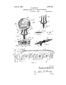
Still another objectlofthe invention is to provide flat connecting members as terminals for the telephone connecting cords arranged to cooperate with the clamping device within the telephone receiver casing operative from the exterior of the casingto clamp the at terminal members rigidly between flatsurfaces-withalllive parts well insulated. Other and further objects of my invention will be-gointed out in the following specifi cation y reference to the accompanying drawings, in which: -."6o Fig. 1 is a perspective view of my'tel phone headset showing the arrangementoi the connecting member which serves both to relieve the strain from the telephone conductors and electrically con'nect the'electrostatic shield which encases the coiiductors with the telephone=-cups or casings;' Fig. '2 is a rear; plan view of one of the telephone receivers employed in the headsetshowing the arrangement of the telephone conductors and the electrostatic shield connector-and strainrelieving member; Fig. 3 is a front plan view ofone of the telephone receivers with the telephone cap and diaphragm removed, illustrating the clamping device in terior of the telephone receiver casing. whichf 4 is operated from the-exterior of the casing for clamping'the telephone leads in the casing without removing the telephonecap' or diaphragm from the receiver-casing; F ig. 4 so is a cross-sectional view of the' telephone. receiver taken on line 47-4 of Fig-3; Fig.1.) is a planviw showing one armngement of the terminals for the telephone cords with the-strain relieving member and electrical connector for the electrostatic shield and'the telephone receivercasing disposed interme--' diate' the telephone conductors; Fig. 6 .is a side view showing the fiat construction of the terminals for the telephone conductcrsg' Fig. 7 is an end view of one of the fiat ter-' minals: Fig. 8 is a fragmentary perspective: view of the telephone 'conductors disposed in the electrostatic shield; and Fig. 9 illustrates the applicationof my headset to sensitivc electron tube amplifiers for use in line wire or radio receiving systems.
. My telephone headset is'provided with an electrostatic shield which isthe subject ma'treceivers of the headset with ti jonit-he ex: tremities of the telephone cords and 'onthe' connector which extends from the electrostatic shield surrounding" the telephone cords; At the points the-cords enter the telephone receiver casings I proyidea-short' connector intermediate thap'aig' of connectors which connectwith the telephone cords.--
This short intermediate '00 (actor is electrically connected with the electrostatic shield surrounding the telephone conductprs, and by reason of its short. lengthgwith reference to the adjacent air of connectorsit serves to I remove the mec anical st'rain imposed upon the connectorsby constantf. pulling'o'f the telephone cords. The three'connectors are provided with flat strip-like terminals. The
. the telephone receiver by movement of the clamping block from the exterior of the tele phone receiver. I have discovered that if it becomes necessary to removef the cap and diaphragm of a telephone receiver to attach a new cord, after it has been once adjusted and passed factory inspection, that the adjustment is in many cases destroyed or at least greatly modified. -Heretofore it has been necessary to remove the caps and diaphragms from the telephones when the cord terminals are to be removed or inserted by-means operative on the interior of the receiver cas ng. Undersuch circumstances it is impracticable to expect permanent operation of the telephone receivers, and re- -pairs and readjustmentscf the telephones must be anticipated. .By my resent arrangement 30f terminal clamping means operative from theoutside of the telephone receiver it is unnecessary to remove the caps from the telephones after initial" setting, and in this waythe. receiversmay be per.- manently adjusted. Therefore, the caps on the receivers are secured upon the casings with relatively reat force inasmuch as there is no occasion or the removal thereof.
In Fig. 1, I have shown the telephones 1 and 2 supported in yokes 3 and 4 respectively, carried byseamless fabric webbing headband 5 as more .fully described in my Patent No. 1,447,969 anted March 13, 1923.- The telephone con uctors are carried in flexible cable 6 shown moreclearly in Fig. 8. The cable includes conductorsv .7 and 8 each. being substantially insulated and provided at their extremities with tips 9 and 10 respectively; An electrostatic shield 11 is provided which substantially encases the conleads 15, 16 and 17, and 18, I9 andf20 are formed of fiat stri members as represented hook shaped end 24. The telephone receiver videdf on the extremity of the elect-r static- 79 shield connector 12. the point wh e the 'telephone conductors enter the telephone receivjer casings f1, and 2 the leads are fanned outgas represented at'15, 16 and 17 and 18,
19 {and 20. The electrostatic shield leads '16.?and 19 are'short as compared with the.
telephone conductors 1715 and 1820 're-' spectively; ;'The telephone conductors are own"conta'inin a substantial amount of pl? while the e ectrostatic shield leads 16- an '19} aregshown as taut and subject to an mechanical strain which mightjbe imposed upon the telephone cords. The tips of the in Fi 5, 6 and The connectors 15," 16 and 1 terminate injfla tfstrip members 21, 22' and 23. Each fiat strip member is pro vided with an upturned orsubstantially casing 1 includes'an electromagnetic operatmg mechanism comprising e eet-romagnets 25 and permanent magnets 25'. Asub-- stantially semi-circular terminal block 26- is positioned inthe; casing and maintained relative topermanent magnets 25 by members 261 and 26". "The terminal block includes a -chordal portion 27 which contains a rectangular recess 28. Terminal lugs 29 and 30 are provided in o posits ends Of the rectangular 'recess :28 eac of which present flat surfaces 3l-and' 32 tiv'ely in the plane of the terminal block? A flat ground coxitact 33 is disposed between the terminal lugs 31 and 32'and connected with the metallic casing 1. All live parts are well insulated, and concealed, preventing acci ntal touch; ing by the user. A pair of adiu ting screws 34 are passed through the tertni'nal block 26'from the exterior of the casing 1 and A carry the insulated clamping block 35. The clamping block 35 contains three protruding faces 36, 37 and 38 which al: ut against the fiat surfaces of terminals 23,,22 and 21 respectively when the terminas are inserted through the telephone rece'ver casing 1,
clamping the terminals firmly in electrical contact with lug 31, ground contact 33, and lug 32 respectively. The hook shaped ends 24 on the flat strip-like terminals serve to firmly anchor the connectors in the receiver by drawing clamping block 35 against the flat tcrminals by'operationof screws 34, the hook portions p'rotrudin slightly beyond the side of the clampingb ock Q My headset is particularly adapted for operation with sensitive mnlt -tage'j'electron tube amplifiers. In Fig-9 havearpresentcd the application of'the'mventiontora a iving system. All antenna-syst m 1 i 39 has'been diagrammatically illustrated with a receiving circuit 40 coupled thereto. Two stages of radio frequency amplification 41 and 42'are illustrated in association with detector .43 and two stagesof audio frequency amplification 44 and 45. The
connector 12.which connects with the electrostatic shield-11 is shown connected with the low potential filament circuit46 of the amplifier. .It will be understoodthat the eiectrostatic shield 11 extends: throughout the length of the telephone conductors, eliminating the electrostatic feedback of energy from the telephone circuit to any of'the input circuits with the inherent howling and distortion of the received signals.
From the foregoing dmcription it will be understoqd'that the electrostatic shieldconnector operates to relieve mechanical strain on the telephone cords -at1the .same time that it 'rovides an electrical connection between e shield andthe telephone receiver casings. By loosening screw members 34' the flatstrip-like terminals may be-slipped into the telephone receiver casing from .the
exterior and rigidly clamped to the terminal clamping arrangement may be used with or without the electrostatic shield connector,
and that other modificatidnsmay be made,
and no limitations other than are imposed by the scope. of the appended claims are intended.
Vhat I claim and desire to secure by Let.-
"ters Patent of. the. United States is as follows:
l. A telephone headset. comprising in combination a receiver casing including electromagnetic operating means, a single longitudinally extending clamping means interior of said casing operative from the exterior thereof. a plurality of connections adapted to be completed by said clamping means. a plurality of conductors leading through said casing and secured under said single longitudinally extending clamping means. ourof said twinductors being shorter than the other of said conductors and electricall onnccted to a shield vncasing said other conductors whereby said shorter 'con- (luctor serves to electrically connect said casing with said shield and removes the strain from the other conductors.
2. A telephone headset. comprising in combination a n-ccirer casing. an electromagnetic system carried therein. an ,-insublock in said casing o terminal connecting block in said casing,-a
telephone cord containing a pair of condoctors and a metallic shield extending over said conductors, connections extending from said pairsof conductors and from said shield and secured to said terminal ljlock and within said insulated member, the con-Q nection fromisaid shield serving to relieve the strain between .said pair of conductors and said telephone casing, and electrically connect said shield with, said casing.
3. A telephone headset, comprising incombination Ia receiver casing,- an electro magnetic operating system in said casing, a. unitary longitudinally extending clamping a pair of conductors and a shield surroundmg the conductors, terminal ends fanned rout from saidconductors and electrically connected to said terminal block, and strain relieving means positioned between said pair connect said shield and said casing.
4. A .telephbne headset, comprising in rative from' the extenor thereof, a telcp onecord comprising of conductm-s, and serving-to electrically combination a receiver casing, an electromagnetic system carried in said casing, a un tary longitudinally extending terminal' block having a plurality of connectors thereon, a telep one'connecting cord-having a pair of conductors with terminals for connection to said" connectors on said terminal block, a longitudinally extending clamping means adjacent said terminal block, a flexible metallic 'casin for electrostatically shielding said tele one cord, :1 combined strain member an cured between said shield and saidt'erminal block, and means exterior of said casing. for.
operating said clamping means over thefle'n tire number of said connectors.
5. Atelephone headset, comprising in comhination a receiver casing including clectro' magnetic operating means, longitudinally extending clamping means interior of said casing operative from the exterior thereof,.a longitudinally extending. block adjacent said clamping means, a plurality of flat connectors carried by said block, a pair ofconductors leading through said casing and secured to a pair of said fiat connectors operation of said longitudinally extending clamping means, one of said conductors beingconnectedto another of said flat connectors located between said pair'of conductors and having a shorter lengththan said pair of conductors, a shield encasing said pair of conductors and secured to said longitudinally extending clamping means whereby said shorter conductor serves to electr cally con-. neat said casing with said shield and remove the strain from said other conductorsl electric conductor'se- 6. Electrical connections for telephone re-" eeivers, comprising in combination a telelatcd member forming a housing for a three phone receiver casing, electromagnetic operating means therein, a terminal block adacent-sa'id-means, a chordal portion on said block, a rectangular slottherein, a pair of lugs m opposite ends of said slot and iconnected wlt-h said electromagnetic operating means, a oimd contact-.'intermediate said lugs,"telep onecords having terminal connectors on their extremities arranged to en-' ter one side of said casing and contact with said lugs and'g'round contact, and. means:- in SilldSlOlS operative from the exterion-ofsaid 'casing for firmly :clampingwaid; terminal connectors. ;againstsaid lugs and -grdundcontac't'.'.
Electrical connedtions for-telephone re- "CGIVGIS, comprising in combination a tele- .phone receiver' cas1ng,'electromagnetic oper-.
ating means therein, a terminal block'adjacent saidimeans, a recess insaid'iblock, -con nections from sa electromagnetic means terminating iir sai recess, a plurality of telephone cordslhaving terminal connectors '4 at their. extremities arrangedto-entersaid recess from the exteriorof said casingpand means overlying alllof said :connections in said recess and. operative Ifroin the exterior 'of said casiug for'iclamping said terminal connectors? and said'connections in substanman's in said r cess icbmprising'a block exding ovei all'ofl'said connections in said recess and arranged for longitudinaltravel upon a screw operative from theexterior of [said casing for clamping said terminal con- I nectors and said connections in substantial ielectrical and mechanical contact. F 9.- Electrical connections for telephone re jfceive'rs comprising in combination a tele' phone. receiver casing, electromagnetic operating means therein, a terminal block ad- ,jacent said means, a recess in said block, 5 lugs in opposite ends of said recess connected with said electromagnetic mechanism, a
ground contact in said recess intermediate said lugs, a plurality of telephone conductors each having a terminal for connection 5 with said'lugs and ground contact; a biock disposed in ground c block adjacent each contact and means operative from the exterior ofsaid casing for clamping said terminals betweemsaid lugs and ground contact.
10. Electrical connections for telephone receivers, comprising in combination a talethe fiatportions of said terminal membe said recess over said lugs and tact, a protruding face on saidof said lugs and ground phone receiver casing, electromagnetic-operatmg means there n, a terminal block adjacent said means, a'recess in 'said block, a plurali ty of contacts in. said recess one being grounded to the receiverlcasirig and two 'bemg connected with said electromagnetic mechanism,a set ofxthree flexible connectors having flat terminal strips at their extremi- .1t1es .Jarranged adjacent said contacts, a
clamping block carried in said recess and extending overall of. said contacts and screw "means passing through saidfclamping block on either side of saidlground contact and operative from the e teries-of said casin for clam mg said terminals between sai block an contacts.
11. Electrical connections for telephone receivers, comprising ineombination a 'receiver casing, 1 an electromagnetic z-imechanism therein, a plurality offlat contacts in 35 said casing connected tosaid electromagnetic mechanism, a plurality of telephone 'oonductorsnarranged' to enter said casing, substantiall 'flat terminal" members carried thereby an a fiat clamping' me mber extend, mgo'ver. all of said fiat contacts and farranged to clamp said fiat terminalsfirmly agaii'ist said fiat contacts.
12. Electrical connections for telephone receivers, comprising in combination areceiver casing, an electromagnetic mechanism therein, a plurality of flat contacts in said casing connected (to said electromagnetic mechanism, 'a' plurality of telephoneconductors arranged to enter said casing,- a flat ter shaped end carried by each of 'saidconduc tors and adapted to connect with saidll at contacts, a flat clamping block mounted o'ver .magnetic means; and unitary; means adjacent each end of said terminal block; and
permanent magnetic means for securing both :said terminal block and said permanent magnetic means in said'casing.
14. A telephone receiver, comprising in combination a casing, electromagnetic means;
of said casing, a substantially semi-circular,
parmanent magnetic means' in one portion}? terminal block in anotherportiori of'said casing having its ends extending-to a position adjacent the ends of said permanent i magnetic means, and means secured to said 'mirialmember having a substantially book a casing overlapping the ends of both said terminal block and said permanent magnetic means for binding said terminal block and said permanent magnetic means in said casing.
15. A ceiver having an, electromagnetic operating mechansm, comprising an insulated body portion,-a recess in said body portion, a plurality of electrical contacts m said recess connected with said electromagnetic operating mechanism and an insulated block' ar= ranged to substantially close said recess, a plurality of connecting terminals arranged to extendinto said body portion adjacent said contacts, and means for clamping said block against said terminals whereby electrical connection with said electromagnetic operating mechanism is maintained and substantiall insulated from objects external said y portion.
16. A terminal block for a telephone receiver having an electromagnetic operating mechanism, comprising an insulated substantially semi-circular ring shaped body portion, a recess in one face of said body portion, a plurality of contacts in said recess connected with said electromagnetic operating'mechanism, an insulated block arranged to substantially close said recess and abut terminal block for a telephone reagainst said contacts, a plurality of connecting. terminals arranged to enter one side of sald body portion and abut with said contacts, a'nd means for clamping said block relative to saidbody portion for maintaining'firm electrical connection between said contacts'and terminals whereby said body portion is substantially insulated on all sides thereof. 1 l
17.11 terminal block for a telephone receiver having an electromagnetic operating mechanism, comprising an insulated bod portion, a recess in said body portion cgcten ing downwardly from the top face thereof,
a pair of metallic angular members carried in said body portion at o posite ends of said recess, each of said mem rs extending into said recess, connections between said members adjacent the top face of said body portion and said electromagnetic operating mechanism, an insulated block arranged to substantially close said recess, a set of terminals'arranged to enter one side of said body portion and connect with said contacts, and means for drawing said block and body portion together whereby said contacts and terminals are firmly clamand insulated from objects-exterior to said body portion.
FREDERICK DIETRICILI
Priority Applications (3)
| Application Number | Priority Date | Filing Date | Title |
|---|---|---|---|
| US672949A US1544136A (en) | 1923-11-05 | 1923-11-05 | Electrical connection for telephone headsets |
| GB7544/24A GB224493A (en) | 1923-11-05 | 1924-03-25 | Electrical connections for telephone headsets |
| FR588506D FR588506A (en) | 1923-11-05 | 1924-11-04 | Electrical connections for telephone headset |
Applications Claiming Priority (1)
| Application Number | Priority Date | Filing Date | Title |
|---|---|---|---|
| US672949A US1544136A (en) | 1923-11-05 | 1923-11-05 | Electrical connection for telephone headsets |
Publications (1)
| Publication Number | Publication Date |
|---|---|
| US1544136A true US1544136A (en) | 1925-06-30 |
Family
ID=24700687
Family Applications (1)
| Application Number | Title | Priority Date | Filing Date |
|---|---|---|---|
| US672949A Expired - Lifetime US1544136A (en) | 1923-11-05 | 1923-11-05 | Electrical connection for telephone headsets |
Country Status (3)
| Country | Link |
|---|---|
| US (1) | US1544136A (en) |
| FR (1) | FR588506A (en) |
| GB (1) | GB224493A (en) |
Cited By (1)
| Publication number | Priority date | Publication date | Assignee | Title |
|---|---|---|---|---|
| USD303531S (en) | 1986-07-15 | 1989-09-19 | Brusseau Curtis L | Headset for the hearing impaired |
-
1923
- 1923-11-05 US US672949A patent/US1544136A/en not_active Expired - Lifetime
-
1924
- 1924-03-25 GB GB7544/24A patent/GB224493A/en not_active Expired
- 1924-11-04 FR FR588506D patent/FR588506A/en not_active Expired
Cited By (1)
| Publication number | Priority date | Publication date | Assignee | Title |
|---|---|---|---|---|
| USD303531S (en) | 1986-07-15 | 1989-09-19 | Brusseau Curtis L | Headset for the hearing impaired |
Also Published As
| Publication number | Publication date |
|---|---|
| FR588506A (en) | 1925-05-08 |
| GB224493A (en) | 1925-06-25 |
Similar Documents
| Publication | Publication Date | Title |
|---|---|---|
| US7553195B2 (en) | Plug | |
| US3201530A (en) | Modular component assembly of microphones | |
| CA1055603A (en) | Radio frequency connector system for portable radios | |
| AU2008207442B2 (en) | Hearing apparatus with a common connection for shielding and identification of a receiver | |
| KR100316789B1 (en) | Connector compatible with balanced and unbalanced audio transmission lines | |
| KR101738902B1 (en) | High-quality sound speaker using dynamic speaker and piezoelectric element | |
| US2755452A (en) | Electrical connector | |
| US1544136A (en) | Electrical connection for telephone headsets | |
| KR860003181Y1 (en) | Jack | |
| US2823358A (en) | Coaxial switches | |
| US3864531A (en) | Microphone and connector unit therefor | |
| JPS58162200A (en) | Hearing aid | |
| US2731614A (en) | Coaxial-type multiple conductor contact plug | |
| FR2280283A1 (en) | Headphones with one or two earpieces - have earphones mounted in earpieces which have contacts switching them on or off | |
| CN109445104B (en) | Plug-in strap-on headset | |
| JPH03266382A (en) | Multicontact coaxial shell connector | |
| US3102172A (en) | Hearing aid | |
| CN215771780U (en) | First connector and connector assembly | |
| US2233848A (en) | Audiphone | |
| US1340955A (en) | Telephone set | |
| US2093664A (en) | Acoustic device | |
| US2267808A (en) | Electromagnetic device | |
| US1636765A (en) | Wave-transmission system and apparatus | |
| CN112788457B (en) | earphone | |
| US2380438A (en) | Microphone circuit |