US1542016A - Permutation lock - Google Patents
Permutation lock Download PDFInfo
- Publication number
- US1542016A US1542016A US69739824A US1542016A US 1542016 A US1542016 A US 1542016A US 69739824 A US69739824 A US 69739824A US 1542016 A US1542016 A US 1542016A
- Authority
- US
- United States
- Prior art keywords
- barrel
- sleeve
- shackle
- groove
- stud
- Prior art date
- Legal status (The legal status is an assumption and is not a legal conclusion. Google has not performed a legal analysis and makes no representation as to the accuracy of the status listed.)
- Expired - Lifetime
Links
- PEDCQBHIVMGVHV-UHFFFAOYSA-N Glycerine Chemical compound OCC(O)CO PEDCQBHIVMGVHV-UHFFFAOYSA-N 0.000 description 1
- 241000234435 Lilium Species 0.000 description 1
- 101150109818 STU1 gene Proteins 0.000 description 1
Images
Classifications
-
- E—FIXED CONSTRUCTIONS
- E05—LOCKS; KEYS; WINDOW OR DOOR FITTINGS; SAFES
- E05B—LOCKS; ACCESSORIES THEREFOR; HANDCUFFS
- E05B37/00—Permutation or combination locks; Puzzle locks
- E05B37/08—Permutation or combination locks; Puzzle locks with tumbler discs on a single axis, all the discs being adjustable by a rotary knob which is not shifted for adjusting the discs
- E05B37/10—Permutation or combination locks; Puzzle locks with tumbler discs on a single axis, all the discs being adjustable by a rotary knob which is not shifted for adjusting the discs in padlocks
-
- Y—GENERAL TAGGING OF NEW TECHNOLOGICAL DEVELOPMENTS; GENERAL TAGGING OF CROSS-SECTIONAL TECHNOLOGIES SPANNING OVER SEVERAL SECTIONS OF THE IPC; TECHNICAL SUBJECTS COVERED BY FORMER USPC CROSS-REFERENCE ART COLLECTIONS [XRACs] AND DIGESTS
- Y10—TECHNICAL SUBJECTS COVERED BY FORMER USPC
- Y10T—TECHNICAL SUBJECTS COVERED BY FORMER US CLASSIFICATION
- Y10T70/00—Locks
- Y10T70/40—Portable
- Y10T70/402—Fetters
- Y10T70/409—Shackles
-
- Y—GENERAL TAGGING OF NEW TECHNOLOGICAL DEVELOPMENTS; GENERAL TAGGING OF CROSS-SECTIONAL TECHNOLOGIES SPANNING OVER SEVERAL SECTIONS OF THE IPC; TECHNICAL SUBJECTS COVERED BY FORMER USPC CROSS-REFERENCE ART COLLECTIONS [XRACs] AND DIGESTS
- Y10—TECHNICAL SUBJECTS COVERED BY FORMER USPC
- Y10T—TECHNICAL SUBJECTS COVERED BY FORMER US CLASSIFICATION
- Y10T70/00—Locks
- Y10T70/40—Portable
- Y10T70/413—Padlocks
- Y10T70/417—Combination-controlled
- Y10T70/422—Rigid shackle
Definitions
- lily invention relates to permutation loclrs and has for its principal object to provide a device oi' this character which is of eX- treme simplicity and 'is therefore rather inexpensive, yet is highly eii'icient and desirable.
- a substantially C-shaped shackle is provided, with its ends turned inwardly and disposed in alined spaced relation, and a rotatable barrel which controls the permutation lockingI means, normally receives both ends oit the shackle, but is adapted to slide entirely onto one end thereof, when the lock is released.
- a further object is to provide novel co'acting means between the other end of the shackle and one end of the barrel, permit! tins, ⁇ release of the lock when it is impossible to see the same, for instance, at night.
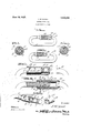
- Figures 1 and 2 are side elevations shown ing the device respectively looked and unlocked.
- Figure 3 is an enlarged sectional view partly in elevation showing the device unlocked.
- Figure 4 is 'an enlarged longitudinal seetional view showing' 'the device locked.
- Figure 5 is a disassembled perspective view of parts oi the lock
- Figures 6 and 7 are transverse sections as indicated by lines 6-6 and 7-7 ot Fig. 4.
- the numeral 1 designates a one-piece, substantially Cshaped shaclrle having its ends 2 and 3 turned inwardly and disposed in alined spaced relation, the end 2 being, ⁇ straight i'or a considerable distance and in the present showing, being provided with one longitudinal groove 4 and with three transverse or circumferential grooves 5, 6
- a sleeve 8 trictionally surrounds the shackle end 2 'and is both rotatable and slidable thereon, said sleeve being ⁇ byv preterence split longitudinally as indicated at 9, to allo-w it to trictionally grip the shaclrle end in an effective manner.
- l have Lshown this sleeve provided with an inwardly eX- tending stud 10 which is received normally in the groove 6, but is also adapted to be received 'in the longitudinal :groove 4, as will be hereinafter more ⁇ i'f'ully explained.
- the sleeve 6 is also provided with a transverse slot 11 from its exterior to its interior, which slot registers with the groove 5;
- Rotatably surrounding the sleeve 8, l have shown an operating barrel 12, one end of which receives the shackle end 3 when the device is locked as shown in Figs. 1 and 4, or is about to be locked'.
- This barrel is provided with a ⁇ stud 13 which extends inwardly, entirely through the slot 11, and has its inner end received in the groove 5. It will thus be seen that by proper manipulation of the barrel 12, the stud 13 will engage an end of ⁇ the slot 11 and move the sleeve 8 until'its stud 10 is alihed with the groove 4.-V Then, further turning of the barrel 12 to the proper extent, will aline the inner end of the stud 13 with said groove 4.
- the barrel 12 and sleeve 8 may be bodily moved baclr upon the shackle end 2 to en ⁇ pose the other end 3 of the shackle.
- a second sleeve 14 which slidably and rotatably surrounds the shackle end 2 and is confined between the inner endet the sleeve 8 and an internal shoulder 15 with which the barrel 12 is provided, said sleeve 14, like the sleeve l8 being housed within said barrel.
- the sleeve 14 is provided with a stud 16 received in the groove 7 when the device is locked, but the inner ends ot the sleeves 8 and 14 areu shaped to provide spaced co-acting shoulders 17, by means of which said sleeve 14 may be turned, when the sleeve 8 is turned.
- the sleeve 14 may be positioned to dispose its stud 16 for movement in the longitudinal groove 4.
- one of the grooves or the like 2() is deeper than the others, or provision is otherwise made for identifying this particular groove, even though it cannot be seen.
- the starting point for opening the lock may readily be determined at night and by counting the proper number of clicks as the notches 2O successively engage the projection 19, it will be seen that the barrel 12 may be manipulated in the proper manner for opening the lock.
- a lock comprising a shackle having a straight portion formed with registering longitudinal and transverse grooves, a sleeve frictionally surrounding said straight portion of said shackle and having a stud received normally in a transverse groove thereof but adapted for reception also in a longitudinal groove of said shackle portion, said sleeve having a transverse slot from its exterior to its interior, and an operating barrel rotatably surrounding said sleeve and having a stud extending inwar lly through the aforesaid slot and normally received in a transverse groove of said straight shackle portion, the last named stud being adapted also for reception in a longitudinal groove of said shackle portion when the first named stud is similarly positioned, whereby the barrel and sleeve as a unit are longitudinally slidable with respect to the shackle.
- a lock comprising a shackle of substantially C-shape with its ends turned inwardly into spaced alined relation, a barrel slidable and rotatable on said shackle ends and adapted to be moved entirely onto one of said ends, a projection on the other end of said shackle normally abutting an end of the barrel, and permutation locking means for said barrel disposed within and operable by the same, said end of said barrel having notches to successively engage said projection when the barrel is turned to operate said permutation locking means, provision being made for identifying one of said notches without viewing the same.
Landscapes
- Hooks, Suction Cups, And Attachment By Adhesive Means (AREA)
Description
June 16, 1925. A 1,542,016
J..H.STU1 L PERMUTATION LOCK Filed March 6, 1924 Patented June lfd, ldtl'i.
unirN STATES,
moon rinnnvsrinn, orrnnrronr, cette.
enamorarme Loon.
Appueanmfmed March c, 1924. seriali no. ceases.
To all whom 'it may concern: v
Be it known that I, .Moon H. S'rULL, a citizen oi the United States, residing at Fremont, in the county ol' Sandusky and' State oi Ohio, have invented certain new and useful Improvements in Permutation Locks; and l do declare the following` to be a full, clear, and exact description ot the invention, such as will enable others skilled in the art to which 'it appertains to inalie and use 'the same. n
lily invention relates to permutation loclrs and has for its principal object to provide a device oi' this character which is of eX- treme simplicity and 'is therefore rather inexpensive, yet is highly eii'icient and desirable.
In the preferred term oit the device, a substantially C-shaped shackle is provided, with its ends turned inwardly and disposed in alined spaced relation, anda rotatable barrel which controls the permutation lockingI means, normally receives both ends oit the shackle, but is adapted to slide entirely onto one end thereof, when the lock is released.
A further object is to provide novel co'acting means between the other end of the shackle and one end of the barrel, permit! tins,` release of the lock when it is impossible to see the same, for instance, at night.
TWith the foregoing in view, the invention resides in the novel subject matter hereinL ritter described and claimed, the description beii'ig supplemented by the accompanying.
drawing.
Figures 1 and 2 are side elevations shown ing the device respectively looked and unlocked.
Figure 3 is an enlarged sectional view partly in elevation showing the device unlocked. Y
Figure 4 is 'an enlarged longitudinal seetional view showing' 'the device locked.
Figure 5 is a disassembled perspective view of parts oi the lock;
Figures 6 and 7 are transverse sections as indicated by lines 6-6 and 7-7 ot Fig. 4.
In the drawings above briefly described, the numeral 1 designates a one-piece, substantially Cshaped shaclrle having its ends 2 and 3 turned inwardly and disposed in alined spaced relation, the end 2 being,` straight i'or a considerable distance and in the present showing, being provided with one longitudinal groove 4 and with three transverse or circumferential grooves 5, 6
and Y, all of which communicate with the groove 4. A sleeve 8 trictionally surrounds the shackle end 2 'and is both rotatable and slidable thereon, said sleeve being` byv preterence split longitudinally as indicated at 9, to allo-w it to trictionally grip the shaclrle end in an effective manner. l have Lshown this sleeve provided with an inwardly eX- tending stud 10 which is received normally in the groove 6, but is also adapted to be received 'in the longitudinal :groove 4, as will be hereinafter more `i'f'ully explained. The sleeve 6 is also provided with a transverse slot 11 from its exterior to its interior, which slot registers with the groove 5;
Rotatably surrounding the sleeve 8, l have shown an operating barrel 12, one end of which receives the shackle end 3 when the device is locked as shown in Figs. 1 and 4, or is about to be locked'. This barrel is provided with a` stud 13 which extends inwardly, entirely through the slot 11, and has its inner end received in the groove 5. It will thus be seen that by proper manipulation of the barrel 12, the stud 13 will engage an end of `the slot 11 and move the sleeve 8 until'its stud 10 is alihed with the groove 4.-V Then, further turning of the barrel 12 to the proper extent, will aline the inner end of the stud 13 with said groove 4. Thus, the barrel 12 and sleeve 8 may be bodily moved baclr upon the shackle end 2 to en` pose the other end 3 of the shackle.
Preferably, although not necessarily used in connection with the features `above de; scribed, is a second sleeve 14 which slidably and rotatably surrounds the shackle end 2 and is confined between the inner endet the sleeve 8 and an internal shoulder 15 with which the barrel 12 is provided, said sleeve 14, like the sleeve l8 being housed within said barrel. The sleeve 14 is provided with a stud 16 received in the groove 7 when the device is locked, but the inner ends ot the sleeves 8 and 14 areu shaped to provide spaced co-acting shoulders 17, by means of which said sleeve 14 may be turned, when the sleeve 8 is turned. Thus, by proper manipulation of sleeve 8, under the influence of the barrel 12, the sleeve 14 may be positioned to dispose its stud 16 for movement in the longitudinal groove 4.
' l have stated abo-ve, that it is not essential to use the sleeve 14, and it is to be understood that when this sleeve is not employed, the additional groove 'l' of the shackle end 2, is not necessary. I prefer however to use the two sleeves and the general association shown, but at this point, it may be further explained that the exact relation of longitudinal and transverse grooves, and inwardly projectingpins herein disclosed, is not essential, as other suitable arrangements could be used. In this connection, attention may be directed to a notch or groove 18, formed in the inner extremity of the shackle end 2 and communicating with the groove 7. This notch or groove is instrumental when initially applyingthe sleeves 8 and 14, as their inwardly extending studs 10 and 15 may be passed through said notch or groove into the groove 7 and turned within the latter, until they can be slid inwardly within the longitudinal groove 4.
Upon the shackle end 3, I have shown a projection 19 which co-acts with a. number of notches, grooves or the like 2() in the adjacent end of the barrel 12, each of said notches or the like having an identifying number. Thus, by setting the barrel 12 with one of the notches engaged with the pin 19, a starting point is provided. The barrel is then turned a specified amount in one direction, next is turned to a predetermined extent in the other direction, and is finally turned in the first named direction to a certain degree. This manipulation of the barrel 12 will aline the three studs 10, 13 and 1G, with the longitudinal groove 4 and the barrel and contained sleeves may then be slid backwardly upon the shackle end 2, to release the lock. Obviously7 a reversal is necessary to lock the device.
Preferably one of the grooves or the like 2() is deeper than the others, or provision is otherwise made for identifying this particular groove, even though it cannot be seen. By this provision, the starting point for opening the lock may readily be determined at night and by counting the proper number of clicks as the notches 2O successively engage the projection 19, it will be seen that the barrel 12 may be manipulated in the proper manner for opening the lock.
As excellent results have been obtained from the details disclosed, they are preferably followed, but within the scope of the invention as claimed, numerous minor changes may be made.
I claim 1. A lock comprising a shackle having a straight portion formed with registering longitudinal and transverse grooves, a sleeve frictionally surrounding said straight portion of said shackle and having a stud received normally in a transverse groove thereof but adapted for reception also in a longitudinal groove of said shackle portion, said sleeve having a transverse slot from its exterior to its interior, and an operating barrel rotatably surrounding said sleeve and having a stud extending inwar lly through the aforesaid slot and normally received in a transverse groove of said straight shackle portion, the last named stud being adapted also for reception in a longitudinal groove of said shackle portion when the first named stud is similarly positioned, whereby the barrel and sleeve as a unit are longitudinally slidable with respect to the shackle.
2. A structure as specified in claim 1; together with an additional sleeve frictionally surrounding said straight shackle portion within said barrel and having a stud normally received in a transverse groove thereof but adapted also for reception in a longitudinal groove of said shackle portion, the two sleeves being in abutting relation and having spaced co-acting shoulders for turning one by means of the other, said barrel having a shoulder abutting the outer end of the additional sleeve to prevent movement of the latter away from the first named sleeve.
3. A lock comprising a shackle of substantially C-shape with its ends turned inwardly into spaced alined relation, a barrel slidable and rotatable on said shackle ends and adapted to be moved entirely onto one of said ends, a projection on the other end of said shackle normally abutting an end of the barrel, and permutation locking means for said barrel disposed within and operable by the same, said end of said barrel having notches to successively engage said projection when the barrel is turned to operate said permutation locking means, provision being made for identifying one of said notches without viewing the same.
In testimony whereof I have hereunto affixed my signature.
JACOB HENRY STULL.
Priority Applications (1)
| Application Number | Priority Date | Filing Date | Title |
|---|---|---|---|
| US69739824 US1542016A (en) | 1924-03-06 | 1924-03-06 | Permutation lock |
Applications Claiming Priority (1)
| Application Number | Priority Date | Filing Date | Title |
|---|---|---|---|
| US69739824 US1542016A (en) | 1924-03-06 | 1924-03-06 | Permutation lock |
Publications (1)
| Publication Number | Publication Date |
|---|---|
| US1542016A true US1542016A (en) | 1925-06-16 |
Family
ID=24800988
Family Applications (1)
| Application Number | Title | Priority Date | Filing Date |
|---|---|---|---|
| US69739824 Expired - Lifetime US1542016A (en) | 1924-03-06 | 1924-03-06 | Permutation lock |
Country Status (1)
| Country | Link |
|---|---|
| US (1) | US1542016A (en) |
Cited By (17)
| Publication number | Priority date | Publication date | Assignee | Title |
|---|---|---|---|---|
| US4155231A (en) * | 1977-04-29 | 1979-05-22 | Kbl Corporation | Bicycle lock and bracket |
| US5010746A (en) * | 1990-04-25 | 1991-04-30 | Kryptonite Corporation | Bicycle lock |
| US5398529A (en) * | 1991-03-07 | 1995-03-21 | Goldman; David S. | Tamper-resistant lock |
| US5694796A (en) * | 1995-03-30 | 1997-12-09 | Couillard; Richard Alexander | Hinged lock with detent positions |
| WO1998057018A1 (en) * | 1997-06-09 | 1998-12-17 | Larsen Allan R | A locking device |
| WO2000053872A1 (en) * | 1999-03-11 | 2000-09-14 | Hanson Luquire L | Padlock |
| USD433310S (en) * | 1999-05-26 | 2000-11-07 | Luquire L Hanson | Shackle for a padlock |
| USD433311S (en) | 1999-05-26 | 2000-11-07 | Shackle for a padlock | |
| USD433312S (en) * | 1999-05-26 | 2000-11-07 | Luquire L Hanson | Shackle for a padlock |
| USD495580S1 (en) | 2003-11-05 | 2004-09-07 | Alloy Metal Manufactory Ltd. | Combination lock |
| USD498132S1 (en) | 2003-07-24 | 2004-11-09 | The Sun Lock Company Ltd. | Combination padlock with horizontal locking bar |
| US20060130539A1 (en) * | 2004-12-21 | 2006-06-22 | Chang-Chiang Yu | Padlock |
| US20130008752A1 (en) * | 2010-03-05 | 2013-01-10 | Meir Avganim | Luggage with built in lock for securing luggage to an immovable object and against the opening thereof |
| USD688114S1 (en) * | 2012-04-12 | 2013-08-20 | Master Lock Company Llc | Lock |
| USD689358S1 (en) | 2012-04-12 | 2013-09-10 | Master Lock Company Llc | Lock |
| USD691458S1 (en) * | 2012-04-12 | 2013-10-15 | Master Lock Company Llc | Lock |
| USD837083S1 (en) * | 2017-10-05 | 2019-01-01 | Tateossian Brands Limited | Bracelet |
-
1924
- 1924-03-06 US US69739824 patent/US1542016A/en not_active Expired - Lifetime
Cited By (24)
| Publication number | Priority date | Publication date | Assignee | Title |
|---|---|---|---|---|
| US4155231A (en) * | 1977-04-29 | 1979-05-22 | Kbl Corporation | Bicycle lock and bracket |
| US5010746A (en) * | 1990-04-25 | 1991-04-30 | Kryptonite Corporation | Bicycle lock |
| US5092142A (en) * | 1990-04-25 | 1992-03-03 | Kryptonite Corporation | Bicycle lock |
| US5398529A (en) * | 1991-03-07 | 1995-03-21 | Goldman; David S. | Tamper-resistant lock |
| US5694796A (en) * | 1995-03-30 | 1997-12-09 | Couillard; Richard Alexander | Hinged lock with detent positions |
| US6442982B1 (en) | 1997-06-09 | 2002-09-03 | Allan Larsen | Locking device |
| WO1998057018A1 (en) * | 1997-06-09 | 1998-12-17 | Larsen Allan R | A locking device |
| WO2000053872A1 (en) * | 1999-03-11 | 2000-09-14 | Hanson Luquire L | Padlock |
| US6227015B1 (en) * | 1999-03-11 | 2001-05-08 | L. Hanson Luquire | Padlock |
| US6415634B2 (en) * | 1999-03-11 | 2002-07-09 | L. Hanson Luquire | Padlock |
| USD433311S (en) | 1999-05-26 | 2000-11-07 | Shackle for a padlock | |
| USD433312S (en) * | 1999-05-26 | 2000-11-07 | Luquire L Hanson | Shackle for a padlock |
| USD433310S (en) * | 1999-05-26 | 2000-11-07 | Luquire L Hanson | Shackle for a padlock |
| USD498132S1 (en) | 2003-07-24 | 2004-11-09 | The Sun Lock Company Ltd. | Combination padlock with horizontal locking bar |
| USD495580S1 (en) | 2003-11-05 | 2004-09-07 | Alloy Metal Manufactory Ltd. | Combination lock |
| US7249475B2 (en) * | 2004-12-21 | 2007-07-31 | Sinox Co., Ltd. | Padlock |
| US20060130539A1 (en) * | 2004-12-21 | 2006-06-22 | Chang-Chiang Yu | Padlock |
| US20130008752A1 (en) * | 2010-03-05 | 2013-01-10 | Meir Avganim | Luggage with built in lock for securing luggage to an immovable object and against the opening thereof |
| USD688114S1 (en) * | 2012-04-12 | 2013-08-20 | Master Lock Company Llc | Lock |
| USD689358S1 (en) | 2012-04-12 | 2013-09-10 | Master Lock Company Llc | Lock |
| USD691458S1 (en) * | 2012-04-12 | 2013-10-15 | Master Lock Company Llc | Lock |
| USD707101S1 (en) * | 2012-04-12 | 2014-06-17 | Master Lock Company Llc | Lock |
| USD724932S1 (en) | 2012-04-12 | 2015-03-24 | Master Lock Company Llc | Lock |
| USD837083S1 (en) * | 2017-10-05 | 2019-01-01 | Tateossian Brands Limited | Bracelet |
Similar Documents
| Publication | Publication Date | Title |
|---|---|---|
| US1542016A (en) | Permutation lock | |
| US1473361A (en) | Key-retaining device | |
| US2356544A (en) | Extensible rule | |
| US2062765A (en) | Doorknob and spindle fastener | |
| US3270538A (en) | Tamper-proof axial tumbler lock | |
| US2076125A (en) | Door lock | |
| US1814302A (en) | Mortise bolt lock | |
| US1679558A (en) | Key | |
| US1908701A (en) | Bar holding device for locks | |
| US1371210A (en) | Clasp | |
| US2167205A (en) | Combination lock | |
| US3413829A (en) | Double cutout spindle cap | |
| US2289129A (en) | Combination tumbler lock | |
| US1911559A (en) | Louis m | |
| US1503043A (en) | Lock | |
| US2021202A (en) | Locking device for foldable measures | |
| US1943704A (en) | Steering wheel lock | |
| US1333887A (en) | Key | |
| US2394248A (en) | Adjustable wagon handle | |
| US1588325A (en) | Extension handle for control levers | |
| US2019400A (en) | Key | |
| US1124862A (en) | Door-lock. | |
| US1482249A (en) | Key | |
| US1974930A (en) | Combination square | |
| US1571125A (en) | Permutation lock |