US1541663A - Air-brake system - Google Patents
Air-brake system Download PDFInfo
- Publication number
- US1541663A US1541663A US2622A US262225A US1541663A US 1541663 A US1541663 A US 1541663A US 2622 A US2622 A US 2622A US 262225 A US262225 A US 262225A US 1541663 A US1541663 A US 1541663A
- Authority
- US
- United States
- Prior art keywords
- valve
- cylinder
- piston
- air
- pipe
- Prior art date
- Legal status (The legal status is an assumption and is not a legal conclusion. Google has not performed a legal analysis and makes no representation as to the accuracy of the status listed.)
- Expired - Lifetime
Links
Images
Classifications
-
- B—PERFORMING OPERATIONS; TRANSPORTING
- B60—VEHICLES IN GENERAL
- B60T—VEHICLE BRAKE CONTROL SYSTEMS OR PARTS THEREOF; BRAKE CONTROL SYSTEMS OR PARTS THEREOF, IN GENERAL; ARRANGEMENT OF BRAKING ELEMENTS ON VEHICLES IN GENERAL; PORTABLE DEVICES FOR PREVENTING UNWANTED MOVEMENT OF VEHICLES; VEHICLE MODIFICATIONS TO FACILITATE COOLING OF BRAKES
- B60T15/00—Construction arrangement, or operation of valves incorporated in power brake systems and not covered by groups B60T11/00 or B60T13/00
- B60T15/02—Application and release valves
- B60T15/36—Other control devices or valves characterised by definite functions
- B60T15/58—Other control devices or valves characterised by definite functions for supplying control impulses through a secondary air pipe
Definitions
- My invention relates broadly to a protec-A tive system for use in traction and more particularly to a construction of air brake system wherein undesired quick action may be positively prevented.
- One of the objects of 4my invention is 'to provide a construction of air brake system which is prevented from functioning Y in emergency position at undesired periods, thereby eliminating the damage to equipment and loading inherent with emergency action of an air brake at a time When such action is not desired.
- Another object of my invention is to provide a positive means for preventing the operatingpiston of the triple ⁇ valve from moving tov emergency position when the air brake system 'is 4functioning in some other position and emergency action is .not desired.
- Still another object of my invention is to provide attachment for a triple valve in an air, brake system by which air underI compression may be introduced on both sides of the pistonin the triplevalve. and preventing the valve from moving to emergency position except when the pressure is reduced on one side ofthe triple valve piston.
- a further object of my invention is to provide an ⁇ air brake system having an auxiliary or emergency train pipe lwhich parallels the brake pipe connecting the several cars of a train, with a r control .connected With the emergency Train pipe ⁇ arrangedr to be operatedavhen the brakes are Jtombe thrown in emergency positionto secure quick act-ion of the triple valve While preventing such action for all otherpositions ofthe tripple valve. o
- a still further object of my invention is to provide a construction of T valve by which the pressure onvone side of the piston in the air brake -systeinmay be regulated from an auxiliary emergency train pipe in such manner that air under pressure will normally prevent quick action of the triple valve While reduction vin pressure in.y the emergency trainpipe and movement of the T valve will operate to cause quick action of the triple valve.'l
- My invention eliminates the destructive ⁇ quick action heretofore inherent in triplev valves at undesired intervals.v
- This undesired emergency action at times when the brakes should function in service or other positions ⁇ often causes destruction to equipment and loading.
- the undesired emergency action may cause draft rigging 'to be pulled out which in turn causes derailment vand Wrecking of cars'and loading and in other casesA it is the cause of cars buckling up and being crushed.
- breaking of this spring is often the cause of undesired quick action or if the triple valve is dry and ,gummyor the brake pipe ⁇ pressure is reduced at too rapid a rate through leakage or otherwise, quick action usually results.
- An independent emergency train pipe isprovided which parallels the normal brake pipe with a connection between theindependent train pipe and the auxiliary, cylinder whereby air under pressure is admitted upon one side of the triple valve piston forming such anvobstrucvtion that the triple valve piston cannot move to emergency position until.
- the pressure 1n .the ar..Xil1aryy ffl cylinder adjacent the triple valve I provide a valve in the engine cab, adjacent the normal engineers valve ⁇ and any number of other valves in the auxiliary train pipo, by which the pressure in the auxiliary train pipe may be reduced siniultaneously with the movement of the engineers valve to emergency position enabling quick action of the triple valve.
- the pressure in the auxiliary train pipe may be suddenly reduced by the parting of cars and rupture of the coupling whereupon the pressure in the auxiliary cylinder is suddenly reduced and the triple valve moved to emergency position.
- order to facilitate operation of the system I provide a T valve connection between the auxiliary pipe line and the connection to the auxiliary cylinder as will be hereinafter described in more detail.
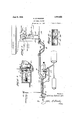
- Figure 1 is a diagrammatic view showing the arrangement of the brake pipe and the auxiliary emergency pipe line, the auxiliary cylinder and the triple valve in the air brake system of my invention
- Fig. 2 shows one construction of the triple valve and the attachment of my invention
- Fig. S shows a modified construction of my attachment for the triple valve
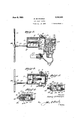
- Fig. 4i is a cross sectional view taken through the T valve employed between the auxiliary train pipe and the connection to the auxiliary cylinder
- Fig. 5 is a cross sectional view of the T valve in position where thc pressure in the, auxiliary train pipe has been reduced and the obstruction removed from the piston.
- F ig. 6 is a cross sectional view taken on line G-G of the T valve illustrated. in Fig. it; and, Fig. T illustrates the piston of the triple valve moved into emergency position against the obstruction offered by the reciprocatoiy piston in the auxiliary cylinder.
- the triple vvalve is represented in general by reference character 1 having a flange 3 against which the auxiliary cylinder 2 abuts and is secured in position against the gasket 4 by means of bolts 5.
- the auxiliary cylinder 2 contains a reciprocatory piston G having a central protruding stem and shoulder 7 :it one side and an extended socket 8 at the other side thereof.
- a central stem 9 having a shoulder 9 abutting the bushing 11 formed in the end wall of the auxiliary cylinder 2has a spring 10 disposed thereon and operating against the extremity of tbc socket 8.
- the auxiliary cylinder 2 is charged with air of auxiliary brake pipe pressure equal to the pressure used inthe triple valve after it been reduced through the slide valve feed valve.
- This air is introduced into the auxiliary cylinder 2 at point 12 through the pipe line 14 which connects by means of the T valve with the emergency tra-in pipe 1G.
- the emergency train pipe 1G may extend from car to car through the flexible couplings 17 and 18, the coupling 19 connecting through riser 2l) with an auxiliary valve 21 in the engine cab 22.
- By opening the valve 21 the pressure in the auxiliary train pipe 16 may be reduced.
- Cutout valves as represented at 23 may be disposed in the auxiliary train pipe 16 at desired intervals along the train to permitl operation of the brake system by remote control.
- operating piston 2-1 arranged to reciprocate in cylinder 25 to move the slide valve 26 to the positions which control the adn'iission of air to parts of the brake system for carrying out the functions of the brake.
- connection to the brake pipe is indicated at 27 joining the brake pipe 28 extending parallel through the car, and being provided with the usual couplings 29 and 30 from car to car.
- the engineers valve 31 is represented as connecting to the brake pipe through riser 32 for controlling the operation of the triple valve.
- the brake pipe may be provided with the usual conductors valve 33 along the length of the train.
- the T valve 15 includes a valve seat 34C having a reciprocatory valve member 35 which normally closes port 36 open to the atn'iosphero as represented in Figure 4t.
- The. T valve contains va cylindrical portion 37 in which' piston 38 is arranged for reciprocatory movement.
- the extremity of the stem 39 fits into socket opening 40 and the piston 3S is arranged to rcciprocate against the action of spring 411.
- Lugs 12 and L13 are provided on the stem 39 for guiding the slide valve rl ⁇ he cylinder Si' is provided in one side with a groove A114: narrowing into a smaller-groove 45 in such arrangement that the air from the branch pipe 16 may feed past the piston 15 into the branch pipe 14 and the emergency cylinder 2 during the process of charging the equipment with air.
- the arrangement of the grooves is such that the piston .38 can move toward the left moving the 'alvc 35 to the left and opening the port- 36 before much air is released from the emergency cylinder 2. This is important so that the The triple valve containsy air is released first from the emergency train y pipe 1G and as quick as possible.
- the port 3G is of an elongated shape as indicated in Figures 2 and 3.
- the groove 1l permits the release of air from the branch pipe 1+i and auxiliary cylinder 2 past the piston 38 after the piston 38 has moved to the left and first opened the port 36 at leaSt half way,
- VfPatei-it fof-fthe'United-States. is as 'folf G in 'reversed'position' to'that illustrated' iii'lowsf'r j Figure 2. That .is to'say ⁇ the ⁇ protruding .f-avl.
- An ⁇ air brake system 'compri-sing in stein and shoulderQTabutstthe 'bushing- 11,' combina-.tion appair '.ofp-pc HQSB avffple' I the l'm'sl1 ⁇ ing'-llI servingasjaguide for they lValve*includingacylinderwithanlroperat L75 stem 7 over the shortdisplacementperiodsI ing pistonstherein, a separate;eylindericonf rl ⁇ he socket 8 servesas a ⁇ guidefor-the stem -rnectedi witlrs'aid irst ⁇ mentioned cylinder.
- the engineer line and said auxiliary cylinder for introlnay make a service application of the brakes ducing air under pressure in said auxiliary im without fear of ⁇ the triple Valve jumping cylinder for controlling the movement of the into emergency position for the valve is piston in said first mentioned cylinder for positively prevented from moving to quick preventing undesired quick action of said action position until the auxiliary Valve is triple Valve. actuated to release air from the rear of pis- S.
- An air brake system comprising in comton (i.
- An air brakesystem comprising in commade the valve 2l is actuated simultaneously bination 'a pair of pipe lines, a triple Valve with the operation of the engineers valve 31 including a cylinder and a reciprocatory and the air in cylinder 2 to the left of piston piston supplied with pressure from one of G is released enabling the triple Valve t0 said pipe lines, a separate cylinder connioie to en'iergency posi-tion as represented nected with said aforementioned cylinder more clearly in Fig. 7.
- auxiliary of said pipe lines ⁇ a reciprocatory piston in Valve may be combined with the engineers said Separate cylinder and means carried valve in such manner that operation of the by said reciprocatory piston in said sepaengineei"s Valve will simultaneously control rate cylinder arranged to form an obstructhe pressure in the auxiliary cylinder 2. It tion in the path of movement of said first will also be understood that other modifica-y mentioned piston upon increase in pressure in said separate cylinder against the piston therein for preventing undesired quick action ot' said triple Valve.
- An air brake system comprising in combination a pair o pipe lines, a triple valve including a cylinder and a reciprocatory piston supplied with pressure from one of said pipe lines, a separate cylinder connected With said aforementioned cylinder and supplied with pressure from the other of said pipe lines, a reciprocatory piston in said separate cylinder, means in each of said pipe lines for independently controlling the pressure supplied to said cylinders -from said pipe lilies, and means carried by the reciprocatory piston in said separate cylinder for forming an obstruction in the path ot' n'iovement ot said first mentioned piston upon increase in pressui'e in said separate cylinder against the piston therein for prevent ing undesired quick action ots-aid triple valve and permitting quick action upon operation oit one of said independent control members and the release ot air pressure in said separate cylinder.
- An air brake system con'iprising in conibination a triple Valve including a cylinder and a reciprocatory piston therein, a second cylinder connected with said aforementioned cylinder and including an independent reciprocatory piston, a pair of pipe lines 'tor supplying air under pressure to each of said cylinders, independent means for controlling the air pressure in each of said pipe lines7 a valve interposed in the connection between one of said pipe lines and said second cylinder whereby upon operation of the control means in said pipe line, the pressure in the pipe line will be reduced prior to the reduc.- tion in pressure in said second cylinder.
- An air brake system comprising ⁇ in coinbination a triple Valve including af cylinder and a reciprocatory piston therein, a second cylinder connected With said aforementioned cylinder and including a reciprocatory piston, a pair of pipe lines ⁇ for supplying ⁇ air under pressure to each of said cylinders, independent means for controlling the air pressure in each of said pipe lines, a T Valve interposed in the connection between one oit said pipe lines and said second cylinder, said T valve including a slide Valve and a controlling piston connected therewithbsaid slide valve normally closinga port to atmosphere in a position wherein said last mentioned piston is positioned adjacent an air feeding groove whereby said second cylinder may be charged with air from said pipe line and the pressure released therein subse quent to the release in pressure in said pipe line.
Landscapes
- Engineering & Computer Science (AREA)
- Transportation (AREA)
- Mechanical Engineering (AREA)
- Valves And Accessory Devices For Braking Systems (AREA)
Description
June 9, 1925.
H. SCHMARGE AIR'BRAKE SYSTEM Filed Jan. 15, 1925 2 Sheets-Sheet l mwmv Mtb mSQSSN at una June 9, 1925. 1,541,663
v H. scHMARGE AIR BRAKE SYSTEM Filed Jan. 15, 1925 2 Sheets-Sheet 2 I ,/E k f 2 3 26' l ,Z. t /6 ff 4 36 l /f/ I 9 l 7 v I 1g 4339 Y l9a II/g3g? 5% f r E L 4g "f/,av//IX/Am 43 a@ Wl/535 5 a a@ a7 Snom/01, /O/z/y/Sf//zf//jya 7 3l( 636@ 3 nog, 'I
I annual ?atented June 9, 1925.
HENRYISCHMARGE, 'OF BELEN, 'NEW MEXICQ.
AIBeBRAKE SYSTEM.
Application filed January To @ZZ fao/7mm it may conce/1in:
Be it known that I, HENRY SCHMARGE., a citizen of the United States, residing at Belen, in the county of Valencia and State of New Mexico, have invented a certain new and useful improvement 'in an Air-Brake System, of which the following is a specilication.
My invention relates broadly to a protec-A tive system for use in traction and more particularly to a construction of air brake system wherein undesired quick action may be positively prevented. l
One of the objects of 4my invention is 'to provide a construction of air brake system which is prevented from functioning Y in emergency position at undesired periods, thereby eliminating the damage to equipment and loading inherent with emergency action of an air brake at a time When such action is not desired.
Another object of my invention is to provide a positive means for preventing the operatingpiston of the triple` valve from moving tov emergency position when the air brake system 'is 4functioning in some other position and emergency action is .not desired.
Still another object of my invention. is to provide attachment for a triple valve in an air, brake system by which air underI compression may be introduced on both sides of the pistonin the triplevalve. and preventing the valve from moving to emergency position except when the pressure is reduced on one side ofthe triple valve piston. A
A further object of my invention is to provide an` air brake system having an auxiliary or emergency train pipe lwhich parallels the brake pipe connecting the several cars of a train, with a r control .connected With the emergency Train pipe` arrangedr to be operatedavhen the brakes are Jtombe thrown in emergency positionto secure quick act-ion of the triple valve While preventing such action for all otherpositions ofthe tripple valve. o
A still further object of my invention is to provide a construction of T valve by which the pressure onvone side of the piston in the air brake -systeinmay be regulated from an auxiliary emergency train pipe in such manner that air under pressure will normally prevent quick action of the triple valve While reduction vin pressure in.y the emergency trainpipe and movement of the T valve will operate to cause quick action of the triple valve.'l
15, i925, Serial No.
My invention eliminates the destructive `quick action heretofore inherent in triplev valves at undesired intervals.v This undesired emergency action at times when the brakes should function in service or other positions `often causes destruction to equipment and loading. The undesired emergency action may cause draft rigging 'to be pulled out which in turn causes derailment vand Wrecking of cars'and loading and in other casesA it is the cause of cars buckling up and being crushed. There are instances Where there may be no visible damage to the equipment and yet the sudden quick action and re' sultant shockwill dislocate and damage :the loading on the inside of the cars. rlhe sudden shocks and stresses are undesirableto the engineer and the railroadv personnel offering serious physical discomfort.l Here'- tofore it has been attempted to prevent undesired quick action byprovidin'g a graduated spring against which the piston-ofthe triple valve may move in one direction. The
breaking of this spring is often the cause of undesired quick action or if the triple valve is dry and ,gummyor the brake pipe `pressure is reduced at too rapid a rate through leakage or otherwise, quick action usually results.
By my invention I eliminate rthe graduated spring` and graduating stem which l have found tovbe ineffective under conditions Where accurate operationof the brakes is essential. In lieu of the graduated spring and stein l provide at one side of the triple valve, adjacent the operating piston .and cylinder thereof, an auxiliary cylinderhaving a. reciprocatory spring-pressed piston therein with a protrliding-head arranged .to obstruct the movementof the triple .valve piston Ainto emergency position'when .such i 'action is not desired. An independent emergency train pipe isprovided which parallels the normal brake pipe with a connection between theindependent train pipe and the auxiliary, cylinder whereby air under pressure is admitted upon one side of the triple valve piston forming such anvobstrucvtion that the triple valve piston cannot move to emergency position until. such a ltime as anen'iergency application of the brake -is desired when the air in back of the'piston is p released causing the piston to moveI back;-
and permitting the triple valve to travel tol quick action or emergency position. In or-V der to control. the pressure 1n .the ar..Xil1aryy ffl cylinder adjacent the triple valve I provide a valve in the engine cab, adjacent the normal engineers valve` and any number of other valves in the auxiliary train pipo, by which the pressure in the auxiliary train pipe may be reduced siniultaneously with the movement of the engineers valve to emergency position enabling quick action of the triple valve. The pressure in the auxiliary train pipe may be suddenly reduced by the parting of cars and rupture of the coupling whereupon the pressure in the auxiliary cylinder is suddenly reduced and the triple valve moved to emergency position. ln order to facilitate operation of the system I provide a T valve connection between the auxiliary pipe line and the connection to the auxiliary cylinder as will be hereinafter described in more detail.
My invention will be more clearly understood Ifrom the following specification by reference to the accompanying drawings7 in which:
Figure 1 is a diagrammatic view showing the arrangement of the brake pipe and the auxiliary emergency pipe line, the auxiliary cylinder and the triple valve in the air brake system of my invention; Fig. 2 shows one construction of the triple valve and the attachment of my invention; Fig. S shows a modified construction of my attachment for the triple valve; Fig. 4iis a cross sectional view taken through the T valve employed between the auxiliary train pipe and the connection to the auxiliary cylinder; Fig. 5 is a cross sectional view of the T valve in position where thc pressure in the, auxiliary train pipe has been reduced and the obstruction removed from the piston. o t the triple valve enabling the valve to move to quick action or emergency position; F ig. 6 is a cross sectional view taken on line G-G of the T valve illustrated. in Fig. it; and, Fig. T illustrates the piston of the triple valve moved into emergency position against the obstruction offered by the reciprocatoiy piston in the auxiliary cylinder.
Referring to the drawings in detail, the triple vvalve is represented in general by reference character 1 having a flange 3 against which the auxiliary cylinder 2 abuts and is secured in position against the gasket 4 by means of bolts 5. The auxiliary cylinder 2 contains a reciprocatory piston G having a central protruding stem and shoulder 7 :it one side and an extended socket 8 at the other side thereof. A central stem 9 having a shoulder 9 abutting the bushing 11 formed in the end wall of the auxiliary cylinder 2has a spring 10 disposed thereon and operating against the extremity of tbc socket 8. The auxiliary cylinder 2 is charged with air of auxiliary brake pipe pressure equal to the pressure used inthe triple valve after it been reduced through the slide valve feed valve. This air is introduced into the auxiliary cylinder 2 at point 12 through the pipe line 14 which connects by means of the T valve with the emergency tra-in pipe 1G. The emergency train pipe 1G may extend from car to car through the flexible couplings 17 and 18, the coupling 19 connecting through riser 2l) with an auxiliary valve 21 in the engine cab 22. By opening the valve 21 the pressure in the auxiliary train pipe 16 may be reduced. Cutout valves as represented at 23 may be disposed in the auxiliary train pipe 16 at desired intervals along the train to permitl operation of the brake system by remote control. operating piston 2-1 arranged to reciprocate in cylinder 25 to move the slide valve 26 to the positions which control the adn'iission of air to parts of the brake system for carrying out the functions of the brake. The connection to the brake pipe is indicated at 27 joining the brake pipe 28 extending parallel through the car, and being provided with the usual couplings 29 and 30 from car to car. The engineers valve 31 is represented as connecting to the brake pipe through riser 32 for controlling the operation of the triple valve. The brake pipe may be provided with the usual conductors valve 33 along the length of the train.
The T valve 15 includes a valve seat 34C having a reciprocatory valve member 35 which normally closes port 36 open to the atn'iosphero as represented in Figure 4t. The. T valve contains va cylindrical portion 37 in which' piston 38 is arranged for reciprocatory movement. A. stein 39 -is provided for guiding the piston 3S. The extremity of the stem 39 fits into socket opening 40 and the piston 3S is arranged to rcciprocate against the action of spring 411. Lugs 12 and L13 are provided on the stem 39 for guiding the slide valve rl`he cylinder Si' is provided in one side with a groove A114: narrowing into a smaller-groove 45 in such arrangement that the air from the branch pipe 16 may feed past the piston 15 into the branch pipe 14 and the emergency cylinder 2 during the process of charging the equipment with air. The arrangement of the grooves is such that the piston .38 can move toward the left moving the 'alvc 35 to the left and opening the port- 36 before much air is released from the emergency cylinder 2. This is important so that the The triple valve containsy air is released first from the emergency train y pipe 1G and as quick as possible. In order to accomplish this quick release the port 3G is of an elongated shape as indicated in Figures 2 and 3. The groove 1l permits the release of air from the branch pipe 1+i and auxiliary cylinder 2 past the piston 38 after the piston 38 has moved to the left and first opened the port 36 at leaSt half way,
1,541gees B My i'i'iyentionl 'is `adaptable.""to"-air brakei'fition eftheinventionmay ybeinadev and that systenisavhich" are a'ta-presentiir'fusel by res intendnomlimitationsupon the invention moving'thejgraduatingspring:andgraduat #other than those imposed-bythe scope of i ing stem and substitutingthef arrangement-'the appendedvclaims; f illustrated in Figui-e3 wherein the-auxiliary '-"""ll1'atI *I claim and desire to secure-by li'et- 7.0. cylinder @includes-'the' rciprocatoryrpiston ters VfPatei-it fof-fthe'United-States. is as 'folf G in 'reversed'position' to'that illustrated' iii'lowsf'r j Figure 2. That .is to'say `the` protruding .f-avl. An `air brake system 'compri-sing in= stein and shoulderQTabutstthe 'bushing- 11,' combina-.tion appair '.ofp-pc HQSB avffple' I the l'm'sl1`ing'-llI servingasjaguide for they lValve*includingacylinderwithanlroperat L75 stem 7 over the shortdisplacementperiodsI ing pistonstherein, a separate;eylindericonf rl`he socket 8 servesas a `guidefor-the stem -rnectedi witlrs'aid irst `mentioned cylinder. S) having shoulda-9a at its:extremityuponwfand including -al reciprocatoiy piston havingl Y which "the springil'o'jis'secured*and againstan axialextension-arrangedtocontactnwith:y which "the spi-ing aibntsc"""1"l1e extremity of a similar axial exten-sion on said iirstmcn-SO the stem 9.is moved to obstruetfth'e'advance-"1t-ionedpiste-ir `and `independent connections I ment ofthe triple:*valvex-pis-tonf'2er-by? iiry between said pipe lines and said cylinders crease-in pressurel inth'e auxiliarycylinder'Q- whereby the stroke'ofsaid iirst mentioned:-
whereas the stem` 9--isretract-eel`- when-"the vpiston* may be" positivelyshortened :by: in pistonGis returned-toits extremes'leftposi;4 "creasing thepressur'e in said separate-cylinv18. tion. It will be fobseryed"that 'the applica# der to,-protrudethe axial extension yon said :n tion of my inyentioirmay be madeiurithout --reciproeatory\Ypistoninfthe pat-lilofsaid first change* in present eq uipment* already --ins mentioned piston `for preventing' undesired stalled'on. the rollingi's'tock. 5*-3 quick-actionof-said triple.L valve.
Quiclactionnftthe triplewialre'#has been iQ. A n air brakesystem comprisingin'com-l e-liminated'by'inysysteinvby'a positive Rob` bination-aibrake-pipe..atriple-:valve sup-.- struction avoidingthe dependence-*ofithe. ae- -pliedffwitlr air underpressurefrom said 1.1.. tion `uponrthe compression"cfa-spring brakepipe;v zii-cylinder insaid triple valves. heretofore vrequired*lin-the art: --Heretofoie i-an operating piston, arranged. for-lreciproca-4 slightdefectiye Workingtofwthe triple Valvetorymovementythereinpanz auxiliaryricylin1952 or the triplepistonfmightmeause the system der adapted to `Ibeconnectedwith said-first to jump into emergency position While the mentioned cylinder, an auxiliary pipe line brake is being applied in a service applicaand a connection between said auxiliary pipe tion. By the system herein the engineer line and said auxiliary cylinder for introlnay make a service application of the brakes ducing air under pressure in said auxiliary im without fear of `the triple Valve jumping cylinder for controlling the movement of the into emergency position for the valve is piston in said first mentioned cylinder for positively prevented from moving to quick preventing undesired quick action of said action position until the auxiliary Valve is triple Valve. actuated to release air from the rear of pis- S. An air brake system comprising in comton (i. Then a service application of the biuation a pair of pipe lines, a triple valve brakes is made, the air to the right 0f the including a cylinder and an operating piston piston 6 will be reduced through standard therein, aseparate cylinder arranged to be equipment butin the Cylinder 2 the PI'GS connected with Said aforementioned cylinsure will remain equal to the pressure'in der, a reciprocatory piston in said separate the pipe line 16 thereby holding piston 6 cylinder and connections between said triplc firmly in a position to form an obstruction vulve and one of Said pipe lines and befor thc triple piStOIl 24. Should thc triple tween said separate cylinder and the other valve tend to jump forward it is prevented of said pipe lines for introducing air under from going into undesired emergency posipressure therein for controlling the movetion by being stopped by the stem 7 in Fig. ment of said rcciprocatory piston and pre- 2 or the stem 9 in Fig. 3. However, when venting undesired quick action thereof. an emergency application of the brakes is il. An air brakesystem comprising in commade the valve 2l is actuated simultaneously bination 'a pair of pipe lines, a triple Valve with the operation of the engineers valve 31 including a cylinder and a reciprocatory and the air in cylinder 2 to the left of piston piston supplied with pressure from one of G is released enabling the triple Valve t0 said pipe lines, a separate cylinder connioie to en'iergency posi-tion as represented nected with said aforementioned cylinder more clearly in Fig. 7. and supplied with pressure from the other It will be understood that the auxiliary of said pipe lines` a reciprocatory piston in Valve may be combined with the engineers said Separate cylinder and means carried valve in such manner that operation of the by said reciprocatory piston in said sepaengineei"s Valve will simultaneously control rate cylinder arranged to form an obstructhe pressure in the auxiliary cylinder 2. It tion in the path of movement of said first will also be understood that other modifica-y mentioned piston upon increase in pressure in said separate cylinder against the piston therein for preventing undesired quick action ot' said triple Valve.
5. An air brake system comprising in combination a pair o pipe lines, a triple valve including a cylinder and a reciprocatory piston supplied with pressure from one of said pipe lines, a separate cylinder connected With said aforementioned cylinder and supplied with pressure from the other of said pipe lines, a reciprocatory piston in said separate cylinder, means in each of said pipe lines for independently controlling the pressure supplied to said cylinders -from said pipe lilies, and means carried by the reciprocatory piston in said separate cylinder for forming an obstruction in the path ot' n'iovement ot said first mentioned piston upon increase in pressui'e in said separate cylinder against the piston therein for prevent ing undesired quick action ots-aid triple valve and permitting quick action upon operation oit one of said independent control members and the release ot air pressure in said separate cylinder.
6. An air brake system con'iprising in conibination a triple Valve including a cylinder and a reciprocatory piston therein, a second cylinder connected with said aforementioned cylinder and including an independent reciprocatory piston, a pair of pipe lines 'tor supplying air under pressure to each of said cylinders, independent means for controlling the air pressure in each of said pipe lines7 a valve interposed in the connection between one of said pipe lines and said second cylinder whereby upon operation of the control means in said pipe line, the pressure in the pipe line will be reduced prior to the reduc.- tion in pressure in said second cylinder.
7. An air brake system comprising` in coinbination a triple Valve including af cylinder and a reciprocatory piston therein, a second cylinder connected With said aforementioned cylinder and including a reciprocatory piston, a pair of pipe lines `for supplying` air under pressure to each of said cylinders, independent means for controlling the air pressure in each of said pipe lines, a T Valve interposed in the connection between one oit said pipe lines and said second cylinder, said T valve including a slide Valve and a controlling piston connected therewithbsaid slide valve normally closinga port to atmosphere in a position wherein said last mentioned piston is positioned adjacent an air feeding groove whereby said second cylinder may be charged with air from said pipe line and the pressure released therein subse quent to the release in pressure in said pipe line.
neuer sci-iMAaen
Priority Applications (1)
| Application Number | Priority Date | Filing Date | Title |
|---|---|---|---|
| US2622A US1541663A (en) | 1925-01-15 | 1925-01-15 | Air-brake system |
Applications Claiming Priority (1)
| Application Number | Priority Date | Filing Date | Title |
|---|---|---|---|
| US2622A US1541663A (en) | 1925-01-15 | 1925-01-15 | Air-brake system |
Publications (1)
| Publication Number | Publication Date |
|---|---|
| US1541663A true US1541663A (en) | 1925-06-09 |
Family
ID=21701661
Family Applications (1)
| Application Number | Title | Priority Date | Filing Date |
|---|---|---|---|
| US2622A Expired - Lifetime US1541663A (en) | 1925-01-15 | 1925-01-15 | Air-brake system |
Country Status (1)
| Country | Link |
|---|---|
| US (1) | US1541663A (en) |
-
1925
- 1925-01-15 US US2622A patent/US1541663A/en not_active Expired - Lifetime
Similar Documents
| Publication | Publication Date | Title |
|---|---|---|
| US1797431A (en) | Braking system | |
| US1541663A (en) | Air-brake system | |
| US2183303A (en) | Air brake | |
| US2035305A (en) | Brake mechanism | |
| US1390597A (en) | A corpora | |
| US2841447A (en) | Electro-pneumatic brake apparatus | |
| US2012375A (en) | Air brake | |
| US1577424A (en) | Air-brake quick emergency control system | |
| US2187966A (en) | High speed brake | |
| US2512046A (en) | Control valve device | |
| US2290948A (en) | Brake control system | |
| US1927964A (en) | Coupler operating valve | |
| US1601906A (en) | Triple-valve air-brake apparatus for trains | |
| US1824044A (en) | Fluid pressure brake | |
| US1104850A (en) | High-pressure emergency-brake. | |
| US432715A (en) | Brake-cylinder head | |
| US825990A (en) | Fluid-pressure brake. | |
| US936415A (en) | Air-brake system. | |
| US1919422A (en) | Fluid pressure brake | |
| US1078017A (en) | Fluid-pressure-brake device for double-heading. | |
| US1125214A (en) | Brake-pipe vent-valve. | |
| US217838A (en) | Improvement in automatic - brake relief-valves | |
| US1633756A (en) | Fluid-pressure-brake system | |
| US2014890A (en) | Triple valve device | |
| US906764A (en) | Means for operating the retaining-valves of an air-brake system from the engine. |