US1540407A - Stop mechanism for talking machines - Google Patents
Stop mechanism for talking machines Download PDFInfo
- Publication number
- US1540407A US1540407A US611248A US61124823A US1540407A US 1540407 A US1540407 A US 1540407A US 611248 A US611248 A US 611248A US 61124823 A US61124823 A US 61124823A US 1540407 A US1540407 A US 1540407A
- Authority
- US
- United States
- Prior art keywords
- trigger
- sound
- stop
- stop member
- record
- Prior art date
- Legal status (The legal status is an assumption and is not a legal conclusion. Google has not performed a legal analysis and makes no representation as to the accuracy of the status listed.)
- Expired - Lifetime
Links
- 230000007246 mechanism Effects 0.000 title description 46
- 238000010276 construction Methods 0.000 description 9
- 241001422033 Thestylus Species 0.000 description 6
- 230000010355 oscillation Effects 0.000 description 5
- 230000000694 effects Effects 0.000 description 4
- 238000012986 modification Methods 0.000 description 2
- 230000002093 peripheral effect Effects 0.000 description 2
- NFLLKCVHYJRNRH-UHFFFAOYSA-N 8-chloro-1,3-dimethyl-7H-purine-2,6-dione 2-(diphenylmethyl)oxy-N,N-dimethylethanamine Chemical compound O=C1N(C)C(=O)N(C)C2=C1NC(Cl)=N2.C=1C=CC=CC=1C(OCCN(C)C)C1=CC=CC=C1 NFLLKCVHYJRNRH-UHFFFAOYSA-N 0.000 description 1
- 241000272470 Circus Species 0.000 description 1
- 241000726306 Irus Species 0.000 description 1
- 241000283986 Lepus Species 0.000 description 1
- 244000261422 Lysimachia clethroides Species 0.000 description 1
- 241000282320 Panthera leo Species 0.000 description 1
- ATJFFYVFTNAWJD-UHFFFAOYSA-N Tin Chemical compound [Sn] ATJFFYVFTNAWJD-UHFFFAOYSA-N 0.000 description 1
- 244000221110 common millet Species 0.000 description 1
- 230000007423 decrease Effects 0.000 description 1
- 239000002783 friction material Substances 0.000 description 1
- 239000010985 leather Substances 0.000 description 1
- 238000012423 maintenance Methods 0.000 description 1
- 238000000034 method Methods 0.000 description 1
- 230000004048 modification Effects 0.000 description 1
- 230000001429 stepping effect Effects 0.000 description 1
Images
Classifications
-
- G—PHYSICS
- G11—INFORMATION STORAGE
- G11B—INFORMATION STORAGE BASED ON RELATIVE MOVEMENT BETWEEN RECORD CARRIER AND TRANSDUCER
- G11B17/00—Guiding record carriers not specifically of filamentary or web form, or of supports therefor
- G11B17/02—Details
Definitions
- a stop mechanism suitable for employment in combination with a talking machine and operative to autoinatical ly stop the revolution of the sound record support after the completion of the reproduction of a selection from the sound record; to provide stop mechanism which may be manually actuated when desired to stop the revolution of the sound record support; to provide stop mechanism adapted for automatic actuation through the instru- [mentality oi. the sound record itself to stop the revolution of the sound record support, and to provide stop mechanism of this character which is simple in construction, comprises but a relatively small number of parts and is posltive 1n operation.
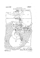
- FIG. 1 is a fragmentary top plan view of a talking machine provided with stop mechanism constructed in accordance with the said preferred form of the invention and showing in full-lines the relation of the several parts when in non-stopping position; other positions of certain of the parts as hereinafter more fully described are indi- "ated in dotted lines.
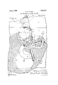
- Fig. 2 is a view substantially similar to Fig. l, but showing the relation of the several parts when in step ping position.
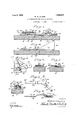
- Fig. 8 is a side elevation of the said mechanism with the trip lever and its pivot stud removed;
- Fig. l is a fragmentary sideelevation of the trip lever illustratmg a convenient arrangement for effecting disengagement of the trip lever from'the actuating stud;
- Fig. 5 is a fragmentary top plan detail view showing one end of the trip lever and associated parts, and Figsio and 7 are respectively vertical sections on the lines (3-(3 and 77 in Fig. olooking in the direction of the arrows.
- Fig. 8 is. a fragmentary yertical section on line 8-8 of Fig. 3 looking in the direction of the arrows;
- Fig. 9 is a top plan View of the trigge-r;
- Fig. 10 is a side elevation'thereof;
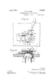
- Fig. 11 illustrates the manner in which my invention may be utilized to operate an electric switch of a talking machine motor instead of a braking mechanism, the parts being shown in stopped position; and
- FIG. 12 is a side elevational view the 'motor board being in section of the-modification shown in Fig. 11. Like numerals are used to indicate the same parts in the several figures.
- FIG. 1 The embodimentof the invention illustrated in the drawings is shown in oper ative association with atalking machine comprising a cabinet having a top conveniently formed with a stationary portion 2 and a movable portion or motor board 3' beneath which is supported the motor or other actuating mechanism (not shown) and above which'is horizontally disposed the usual rotary disk record support or turntables provided with a depending peripheral flange 4 and carried upon and rotated by a spindle 5 ing. mechanism.
- the record support Arranged above the record support is the usual sound box 7 connected to one end of a tubular member or gooseneck 8, the other end of which-is pivotally supported at one end of the hollow tone arm 10 mounted to swing abouta fixed vertical extending through the top" of the cabinet and driven from the actuataxis in the usual manner and arranged to' communicate with a suitable sound a1npli tier (not shown), the sound box bein g' thus adapted for movement about a horizontal axis toward or away from the record support and to swing with the tone arm across the record support about the vertical axis of the former.
- the stop mechanism is-arranged above the cabinet top and preferably mainly beneath the sound record support, and. in its preferred embodiment, comprises a base screws 13 or in any other'suitable way.
- This plate 12 secured to the motor board '3 by base plate is provided with a main portion 14 and with an arm 15 conveniently integral with the main portion and extendin laterally substantially normal thereto rom a point adjacent one of itsends, a function of this arm being to support near itsouter extremity the trip lever ivot stud as here-.-
- the stop member 18 Pivoted on a suitable pivot stud 17 disposed adjacent that end of the main portion of the base farthest removed from the arm 15 is the stop member 18 which may comprise a substantially circular body 18' through which the pivot extends and an outwardly extending curved brake shoe arm 20, the end of which may be turned up vertically and' arranged to supportthe brake shoe 21 of leather or other suitable friction-material adapted to engage the inner face of the downwardly turned peripheral flange 4 of the sound record support when the stop member is moved to stopping postion.
- the stop member is also provided with a preferably substantially a detent arm 29 and a ratchet arm 30 con-.
- the trigger may be supported on the base plate in any suitable way, conveniently through the medium of a sleeve 36 having a flange 37 at its lower end adapted to rest on the base plate, and with its upper part of suitable diameter to fit within the aperture 32 in the trigger.
- This sleeve may be rotatably supported on a pivot pin 38 having a head 39 at its upper end and secured at its'lower end in the base plate, and for holding the trigger in relatively rigid'relation with the sleeve 'a spring washer 4O havin a radial slot 41 whose edges are adapte for engagement in a groove 42 formed in the sleeve adjacent its upper end may be employed, one or more suitable washers 43 being interposed between the under face of the trigger and the flange of the sleeve. if required to fill up the space between these parts.
- 'means are provided, preferably comprising a coil spring 46 having its ends respectively hooked over a lug 47 on the detent armand a lug 48 on the stop member, for rotating the stop member when released from the detent and continuously drawing the detent arm toward the stop member so as to cause the detent to enter the notch whenever the latter is brought into registry therewith, the spring 46 being preferably so arranged that its axis will always lie upon that side of the pivot of the stop member which is most nearly adjacent the detent.
- an upturned stop lu 4:9 is preferably formed on the edge of the hase plate in a position to engage the end of the detent armso as to limit the possible rotation thereof in an anti-clockwise direction, while the stop memher itself is provided with a radial projection 50 of suiiicient length to engage the detent arms when the latter is against the lug 49 and thus ar'restfurther rotation -of the stop member.
- the limit of movement of the stop member in a counterclockwise direction is determined by contact of the brake pad with the flange of the record support, but
- I may provide a notch 51 adjacent the point of juncture of the lever 24 and the portion 18 of the stop member adapted to engage the end of the detent arm and thus limit the extent of counter-e10ckwise movement of the stop member under such conditions.
- a trip lever Pivoted for horizontal oscillation adjacent the outer end of the arm 15 of the base plate is a trip lever generally designated as (50, said lever being preferably supported on a headed pivot stud 61- extending through the lever and screwed or otherwise secured in the arm, a' washer 62 being preferably" interposed between the lever and the arm so as to space the lever slightly thereaboye.
- the outer end of this lever that is, that end most nearly adjacent the pivot of the tone arm, may be provided with a fork 63 adapted to receive the, lower end of an ac- '1 stud 64 carried by and downwardly tuatir n from the tone arm in such inandepei.
- ner that as the tone arin rotates aboutits 1e stud travels in the fork to swing rip lever about the pivot 61 in corresuch manner that the forked portion may be turned up from its normally. horizontal position in the manner indicated in dotted lines in Fig; 4 so as to clear the end of the fork from the actuating stud. when the tone arm is swung outwardly, that is, to-
- the hinge is of such construction as to prevent the forked portion of the arm from being inclinedv downwardly from .the'plane of the other part of the arm. thereby retaining the In order to facilitate disengagement forked portion in substantially horizontal position under normal conditions.
- llllea-ns interposed between the trip lever and the trigger are provided for positively effecting movement of the triggerwheu the trip lever is suitably-actuated, said means conveniently comprising a pawl 68 pivoted at one end through the medium of a suitable pivot stud 69, or the like, adiacent the.
- the rack 70 having teeth 70 and fixedly secured. as by screws 71, to the ratchet arm. 30 of the trigger, the toothed face of the ratchet being preferably formed to coincide, when the detent 4A is in notch 45, with an arc struck from the axis of pivot 61 as a center.
- the rack may be formed integral with the part on which it is disposed, it is preferred to construct the same separately therefrom and secure it thereto as hitherto described, thus enabling therack to be suitably hardened to minimize wear.
- the pawl 68 1s arranged to extend toward the rack and in a direction generally normal to the trip lever and means, conveniently comprising a small downwardly turned (log); 73 engaging in a slot 74 formed in the end of the trip lever, are provided for hunting the amount of relative oscillation betweenthe pawl and the lever, a suitably positioned spring 7 5 having one end soldered or otherwise secured to the lever and the other hooked over the pawlbeing arranged to constantly urge the pawl in' a counte1.clockwise direction with respect to the lever as best shown in 5.
- the teeth L 0 with which the rack is provided are preferably of relatively small size and so arranged that when the detent 4-4 is in notch 45 and the stop member in nonstopping position, the pawl can slide freely thereover when the trip lever is moved in a 4 counter-clockwise direction but will interlock therewith so thatthe trigger will be positively moved ,by the trip lever upon movement of the trip .lever in the opposite direction.
- the width of the slot 74 is sufficient to accord the dog the play requisite, under these conditions, to permit the pawl toride'over the teeth when the trip lever ismoved counterclockwise.
- spring 46 operates to draw the detent 44 into the notch 45, thereby giving to the trigger a slight movement of oscillation in a clockwise direction and bringing the rack 70 to a position suitable for cooperation withthe pawl 68, after which movement of the trip lever, in an anti-clockwise direction is effective to pawl freely over the teeth 70- so.
- thedetentin certainITcon'struc reaches zero an ing to pull t tinned ithrough a relatively short are, the trigger is thereby positively forced in a counter-clockwise direction to disengage the detent 44 from the notch 45 and permit the to move to stopping position and if equipped with a brake shoe,-to press thelatter against the flange 4' to bring the rotating soundrecord supportto rest.
- a suitable sound record is positioned upon the sound -'record support to rotate therewith, sai'drec ord being provided with the usual spiral, laterally undulating sound groove 81 by and in accordance with which the reproducing stylus carried by the sound reproducer 7 is propelled across the record from a point near ;the'outer' margin thereof to a. point more nearly adjacent the center, thus ping position, the sound record 80 may beprovided, in addition to the usual spiral sound grooves 81, with a, supplementary groove 82 which may, as illustrated in Fig. 1, lead from the inner end. of the spiral groove 81 in the form of a circle arranged eccentrically with respect to the record, the
- the stop member when desired by manually swinging the handle in the proper' direction, and that by. effecting a reverse movement of the tone arm through the medium of the record the stop member may be released automatically from non-stopping po sition so as to stop the rotation of the record support substantially simultaneously with or at a predetermined interval after the completion of the sound reproduction from the record.
- the tone arm' is preferably first swung outwardly until the sound reproducer 'and stylus are entirely clear of the record andthe handle 25 then moved so as to.move the stop member to non-stopping position thereby permitting the-detent 44 to enter notch 45, oscillating the trigger and bringing the rack-to a position in which it may be engaged by the pawl.
- This outward movement of the tone arm has brought the trip lever more or less to the position indicated in dotted lines and designated as A in Fig.
- the exact position of the trip lever bein of course, determined by'the extent to which the tone arm has been swungoutwardly. lhe record support, now freed from there straining influence of the brake pad, having commenced to rotate, the tone arm. is swung inwardly and the stylus entered in the outer convolution of the spiral groove in the record in the usual way, thereby bringing thetrip lever substantially to the position indicated in dotted lines and desig nated as B in Fig 1 and with the nose of the pawl in engagement with or approaching engagement with the outer end of the rack.
- stop member or corresponding element 1s utilize for the actuation of electric or other means operative to control the actuating means by which the rotation of th sound record support is effected.
- the main portion 14 of the base plate 12 may be provided-with a circular end 16 having an arc-shaped slot 19, and the brake arm 20 of thepreviously described construction may be replaced by an extension 20 having a slot 22 near the outer end thereof; v
- the switch operating lever 23 of the electric switch 26 extends upwardly through the arc-shaped slot 19 in the baseplate and preferably loosely fits into opening 22 in the ex; tension 20'.
- the said switch 26 is preferably secured to the under side of the end 16 of" the base plate 12 by screws 27.
- The' switch is also provided with posts 33 to which the leads 34: of the motor circuit may be attached,
- the details of the eleotric sw tch may be of any a proved type. I have illustrated one like t at shown in the U. S. Patent No;
- a trip lever pivoted foroscillation in conformity withthe movements of the sound reproducing means, and means carried by the trip lever operative to engage and ride on said rack when the sound reproducing means are moving across the record during reproduction of sound therefrom and to actuate said trigger to release the stop member-from non-stopping position upon movementof said sound reproducing means in the opposite direction.
- a trigger for said support coii'iprising a rotatable stop member, a trigger having arms extending in dverent directions, means carried by one oi said arms operative to hold said stop member in non-stopping position and said other aim being provided with a rack, means for urging said stop member from non-stopping to stopping position, a .trip lever pivoted for oscillation in conformity with the movement of the sound reproducing means, and a pawl carriedby and relatively movable with the trip lever and adapted to engage and ride on sa d rack whe'ii the sound reproducing means are moving across the rerord during"reproduction of sound therefrom and to actuate said trigger to release said stop member from non-stopping position upon movement of the sound reproducing means in the opposite direction.
- a stop mechanism for a talking machine the combination of a movable stop member, a trigger cooperative therewith and having a rack, a movable trip lever; and means carried by thetrip lever and arranged to slideover said rack. upon movementof said trip lever in one-direction and to interlock with said rack and posi ⁇ tively move said trigger with said trip lever upon the movementof the trip lever 8.
- a stop mechanism for a talking machine the combination of a movable stop member, a trigger cooperative therewith and having a rack, a trip lever, and a pawl carried by and movable with respect to the trip lever adapted on relative movement oi the trip lever in one direction with respectto the trigger to ride freely over the rack and to interlock with the rack upon reversal of said movement of the leverto -cause both members to move simultaneously.
- a trigger means carried by the trigger for releasably holdmg: the stop member in one position, means tending to urge the stop member to another position.
- a trip lever adapted for oscilla-. lion. and means carried by and relatively movable with respect to the trip lever operative to move said trigger when the trip lever is rotated in a given direction.
- triggerv is in a given position, an oscilla 7 tory trip lever,fa. member carried by and relatively movable withirespect to the trip lever, means carriedby the other arm of the trigger operative to permit said member to position and the trip lever is moved iii-one direction and to engage and lock with said member when the trip lever is moved in the other direction whereby said. trigger .isf
- a trigger having arms extending in different directions, means carried by one of said arms for holding the stop meinberin a given position, means tendingto rotate said trigger and also to rotate the stop member to another position,
- a rack carried by the'other arm of the trigger, a movable trip lever, and means carried by and relatively movable with respect to the tr p leveroperatwe to engage and traverse said rack when ,the trip lever is movedin one direction and tocoact with said rack when the'triplever is moved in the opposite direction to move said trigger to another position member.
- the COlhblIliLtlOItOf a rotatable stop member, a pivoted trigger having-arms extending in different directions.
- a trigger cooperative with the stop member, a trip lever pivoted for movement in a fixed plane, and means interposed between the trip lever and the trigger adapted on.
- step mechanism for talkmg machines the combination. of a stop member,
- a trip lever having ahorizontally disposed part pivoted for movement in a horizontal plane and-a movable'part hingedly secured tothepivoted part and adapted to be turned upwardly from the plane of said pivoted part, and means interposed between the pivoted part of the triplever and the trigger adapted to lock the trigger and trip lever together upon movement'of the tri lever in a given direction with respect to t e trig- "er. v p k b 17.
- a. talking machine having a rotatable record support and sound reproducmg means arranged for relatlve movement in a predetermined direction with respect to said support to reproduce'sound froma sound record. carried by said support, the
- stop actuating mechanism comprising a member movable. from stopping to non-stopping position, means to move" said member to stopping position, a trigger for holding said member in none stoppingposition, altripconnected to and. operated by the'reproducing means for releasing said trigger upon reverse movement of said reproducingmeans relative to said support, said trigger being arranged to be moved out of cooperative engagement with .Isaid trip 'assaid member moves-to stopping 19,
- a phonograph stop actuating mechanism comprising a member movable from stopping to non-stopping position, means,
- a traveling elementand means whereby the traveling element is givema reverse movement at a predeterminedgpoint in its travel, a brake member,-a detent adapted-- to be -moved in one direction to release said brake member, and a memberf pperatively connectedxto'said.
- traveling ele'ment to slide freely without substantial resistance over said detent during the forward movement of said traveling element and to interlock with and ositively move said detent to release said rake member upon-movement of said traveling member in the reverse direc tion.
- a talking machine having a rotatable record support and sound reproducing means adapted for movement across said support, of stop mechanism a for said support including a movable stop member, "a trigger adapted to retain said stop member in non-stopping position, and a trip element adapted to e positively interlocked with and to operate said trigger upon amovement of said sound reproducing means in a direction opposite from that to reproduce sound.
- a stop mechanism for talking machines the combination of a stop member, a trigger cooperatin with the stop member, a tri -member, a rac carried b one of said mem ers,'and a pawl carried y the other: of said members, said rack and pawl being operativel positioned with respect to each other by t e engagement of said trigger with said stop member to retain the latter in nonstopping position.
- the com ination with a talking machine having a rotatable record so port and sound reproducing means adapte to move across sa1d support, a stop member and" apairof elements, one of which is adapted to cooperate with said stop member'to retain the same in non-stopp1ng position, and means ntermediate sa1d e ements to' lnterlock sa1d elements, upon movement of said sound reproducing means in a direction oposite from that to reproduce sound, wherey said elements are moved together to re;
Landscapes
- Toys (AREA)
Description
June 2, 1925. w. D. LA RUEH' swormzcumxsm FOR TALKING MACHINES 192"" 4 Sheets-Sheet 1 "254, Jan. 8 I
June 2, 1925.
w, D. LA RUE STOP mscwmxsu FOR TALKING MAQHINES Filed Jan. 's.- 1925 4 Sheets-Sheet 2 W M- MW June -2, 1925.
w'. D. LA RUE STOP MECHANISM FOR TALKING MACHINES Filed Jan. 8. 1923 .4 Sheets-Sheet 5 w/TNEs'S June 2, 1925.
w. D. LA, RUE
STO-P MECHANISM FOR TALKING MACHINES Filed Jan. 8. 1923 4 Sheets-Sheet 4 INVE VTUI? Will/lam H za/fi ue,
flTTOF/VEYS June 2 VJILLIAYLVI D. LA RUE, DE BHILADELPHIA, PENNSYLVANIA, ASSIGNOR T0 "V'IC'IQR TALKING MACHINE COMPANY, A CGRPOBATION OF NEW JERSEY.
STOP MECHANISM FOR TALKING MACHINES.
Application filed January "8, 1923. Serial No. 611,248.
T 0 all whom it may (2oncern Be it known that l, rLnmM D. LA Run, a citizen of the United States, and a resident of the city and county of Philadelphia, State of Pennsylvania, have invented certain new and useful Improvetnentsin Stop Mechanisms for Talking Machines, of which the following is a specification, reference being had. to the accompanying drawings.
Among the principal objects of my invention are to provide a stop mechanism suitable for employment in combination with a talking machine and operative to autoinatical ly stop the revolution of the sound record support after the completion of the reproduction of a selection from the sound record; to provide stop mechanism which may be manually actuated when desired to stop the revolution of the sound record support; to provide stop mechanism adapted for automatic actuation through the instru- [mentality oi. the sound record itself to stop the revolution of the sound record support, and to provide stop mechanism of this character which is simple in construction, comprises but a relatively small number of parts and is posltive 1n operation.
The foregoing objects, as well as various.
other objects and novel features of construction and arrangement will hereafter more fully appear from the following descrlption taken in connection with theaccompanying drawings forming a part thereof.
In the said drawings 1 have illustrated a preferred embodiment of the invention in operative association and combination with a talking machine of well known form, only so much of the'latter, however, being shown as is requisite for an adequate comprehension of the invention.- More particularly, Fig. 1 is a fragmentary top plan view of a talking machine provided with stop mechanism constructed in accordance with the said preferred form of the invention and showing in full-lines the relation of the several parts when in non-stopping position; other positions of certain of the parts as hereinafter more fully described are indi- "ated in dotted lines. Fig. 2 is a view substantially similar to Fig. l, but showing the relation of the several parts when in step ping position. Fig. 8 is a side elevation of the said mechanism with the trip lever and its pivot stud removed; Fig. l is a fragmentary sideelevation of the trip lever illustratmg a convenient arrangement for effecting disengagement of the trip lever from'the actuating stud; Fig. 5 is a fragmentary top plan detail view showing one end of the trip lever and associated parts, and Figsio and 7 are respectively vertical sections on the lines (3-(3 and 77 in Fig. olooking in the direction of the arrows. Fig. 8 is. a fragmentary yertical section on line 8-8 of Fig. 3 looking in the direction of the arrows; Fig. 9 is a top plan View of the trigge-r; Fig. 10 is a side elevation'thereof; Fig. 11 illustrates the manner in which my invention may be utilized to operate an electric switch of a talking machine motor instead of a braking mechanism, the parts being shown in stopped position; and Fig.
12 is a side elevational view the 'motor board being in section of the-modification shown in Fig. 11. Like numerals are used to indicate the same parts in the several figures.
The embodimentof the invention illustrated in the drawings is shown in oper ative association with atalking machine comprising a cabinet having a top conveniently formed with a stationary portion 2 and a movable portion or motor board 3' beneath which is supported the motor or other actuating mechanism (not shown) and above which'is horizontally disposed the usual rotary disk record support or turntables provided with a depending peripheral flange 4 and carried upon and rotated by a spindle 5 ing. mechanism. Arranged above the record support is the usual sound box 7 connected to one end of a tubular member or gooseneck 8, the other end of which-is pivotally supported at one end of the hollow tone arm 10 mounted to swing abouta fixed vertical extending through the top" of the cabinet and driven from the actuataxis in the usual manner and arranged to' communicate with a suitable sound a1npli tier (not shown), the sound box bein g' thus adapted for movement about a horizontal axis toward or away from the record support and to swing with the tone arm across the record support about the vertical axis of the former.
The stop mechanism is-arranged above the cabinet top and preferably mainly beneath the sound record support, and. in its preferred embodiment, comprises a base screws 13 or in any other'suitable way. This plate 12 secured to the motor board '3 by base plate is provided with a main portion 14 and with an arm 15 conveniently integral with the main portion and extendin laterally substantially normal thereto rom a point adjacent one of itsends, a function of this arm being to support near itsouter extremity the trip lever ivot stud as here-.-
inafter more particularly escribed. Pivoted on a suitable pivot stud 17 disposed adjacent that end of the main portion of the base farthest removed from the arm 15 is the stop member 18 which may comprise a substantially circular body 18' through which the pivot extends and an outwardly extending curved brake shoe arm 20, the end of which may be turned up vertically and' arranged to supportthe brake shoe 21 of leather or other suitable friction-material adapted to engage the inner face of the downwardly turned peripheral flange 4 of the sound record support when the stop member is moved to stopping postion. The stop member is also provided with a preferably substantially a detent arm 29 and a ratchet arm 30 con-.
veniently disposed in somewhat angular relation to each other preferably substantially jinthe same horizontal plane and a boss 31 rovided with a circular aperture 32 said oss being disposed adjacent the point of juncture of the arms and preferably in a plane somewhat above the plane or planes of the latter, as-clearly shown in Fig. 10. p
The trigger may be supported on the base plate in any suitable way, conveniently through the medium of a sleeve 36 having a flange 37 at its lower end adapted to rest on the base plate, and with its upper part of suitable diameter to fit within the aperture 32 in the trigger. This sleeve may be rotatably supported on a pivot pin 38 having a head 39 at its upper end and secured at its'lower end in the base plate, and for holding the trigger in relatively rigid'relation with the sleeve 'a spring washer 4O havin a radial slot 41 whose edges are adapte for engagement in a groove 42 formed in the sleeve adjacent its upper end may be employed, one or more suitable washers 43 being interposed between the under face of the trigger and the flange of the sleeve. if required to fill up the space between these parts. Thus in assembling, after the pivot pin is passed throu h the sleeve, its lower end may be inserte in an aperture in the base plate and then headed over so asto secure the pin in osition in such manner that the sleeve is reely rotatable thereon; the washers 43 and trigger may then be slip ed onto the upper end of the sleeve over the ead of thepivot and the spring washer slid into"pos ition.above the trigger so as to engage the groove in the sleeve and press er 111 such manner that when the detent is I in the notch the lever is normally prevented from rotation about its pivot and maintained in a position, as in Fig. l, in which the brake shoe 21 is out of contact with the flange 4 of the sound record support, and
'means are provided, preferably comprising a coil spring 46 having its ends respectively hooked over a lug 47 on the detent armand a lug 48 on the stop member, for rotating the stop member when released from the detent and continuously drawing the detent arm toward the stop member so as to cause the detent to enter the notch whenever the latter is brought into registry therewith, the spring 46 being preferably so arranged that its axis will always lie upon that side of the pivot of the stop member which is most nearly adjacent the detent.
To facilitate manual actuation of the stop;
member at any time, I preferably so form the coacting faces of the detent 44 and the notch 45 that when thedetent is held in the notch by the tension of spring46 the releasing and resetting lever 24 may bemanually rotated in a counter-clockwise direction so as to disengage the detent from the notch and permit the stop member to move to stopping position, the 'end of the detent meanwhile riding on the. cam surface 45' which may be provided on the stop member adjacent the notch, while,'on the other hand, when the detent is in the notch it I cannot be disengaged therefrom by movement of the lever 24in a clockwise direction. Thus when the stop mechanism is being reset frorn stopping to non-stopping position as hereinafter more fully described,
the releasing and resetting lever cannot be moved in a clockwise direction through, an
are greater than that required to bring the notch into registration with the detent, for as soon as such registration is effected the detent enters the notch and thereafter. prevents further revolution of the lever.
For the purpose of preventing the stop member from being rotated suiliciently to cause the axis of the spring 46 to cross the pivot in case the detentfis accidentally or otherwise prevented from engaging in the notch during clockwise rotation of the lever, an upturned stop lu 4:9 is preferably formed on the edge of the hase plate in a position to engage the end of the detent armso as to limit the possible rotation thereof in an anti-clockwise direction, while the stop memher itself is provided with a radial projection 50 of suiiicient length to engage the detent arms when the latter is against the lug 49 and thus ar'restfurther rotation -of the stop member. Thus, at all times the tendency of the spring 4:6 to effect rotation of the stop member in a counter-clockwise direction so as to pull the brake shoe into. engagement withthe flange of the sound record support'is insured, the detent being, however, operative to hold the stop member, against the tension ofthe spring- L6, in a position in which the shoe is out of engagement with the sound record support whenever the detent is engaged within the notch.
It will, of course, be evident that or-.
dinarily when the sound recordsupport is in operative position on the talking machine, the limit of movement of the stop member in a counterclockwise direction is determined by contact of the brake pad with the flange of the record support, but
for preventing excessive rotation of the lever in such direction, if for any reason the record support be entirely removed or lifted sutiiciently'to bring the flange 4 out of alignment with the brake pad, I may provide a notch 51 adjacent the point of juncture of the lever 24 and the portion 18 of the stop member adapted to engage the end of the detent arm and thus limit the extent of counter-e10ckwise movement of the stop member under such conditions.
Pivoted for horizontal oscillation adjacent the outer end of the arm 15 of the base plate is a trip lever generally designated as (50, said lever being preferably supported on a headed pivot stud 61- extending through the lever and screwed or otherwise secured in the arm, a' washer 62 being preferably" interposed between the lever and the arm so as to space the lever slightly thereaboye. The outer end of this lever, that is, that end most nearly adjacent the pivot of the tone arm, may be provided with a fork 63 adapted to receive the, lower end of an ac- '1 stud 64 carried by and downwardly tuatir n from the tone arm in such inandepei. g
ner that as the tone arin rotates aboutits 1e stud travels in the fork to swing rip lever about the pivot 61 in corresuch manner that the forked portion may be turned up from its normally. horizontal position in the manner indicated in dotted lines in Fig; 4 so as to clear the end of the fork from the actuating stud. when the tone arm is swung outwardly, that is, to-
ward the right hand edge of the sheet when viewed as in Fig. .1, substantially to the limit of its possible movement in that di' rection, while, on the other hand, the hinge is of such construction as to prevent the forked portion of the arm from being inclinedv downwardly from .the'plane of the other part of the arm. thereby retaining the In order to facilitate disengagement forked portion in substantially horizontal position under normal conditions.
llllea-ns interposed between the trip lever and the trigger are provided for positively effecting movement of the triggerwheu the trip lever is suitably-actuated, said means conveniently comprising a pawl 68 pivoted at one end through the medium of a suitable pivot stud 69, or the like, adiacent the.
oppositeend of the trip lever and cooperative at its other or free end with a rack 70 having teeth 70 and fixedly secured. as by screws 71, to the ratchet arm. 30 of the trigger, the toothed face of the ratchet being preferably formed to coincide, when the detent 4A is in notch 45, with an arc struck from the axis of pivot 61 as a center. hile in certain constructions the rack may be formed integral with the part on which it is disposed, it is preferred to construct the same separately therefrom and secure it thereto as hitherto described, thus enabling therack to be suitably hardened to minimize wear. j
The pawl 68 1s arranged to extend toward the rack and in a direction generally normal to the trip lever and means, conveniently comprising a small downwardly turned (log); 73 engaging in a slot 74 formed in the end of the trip lever, are provided for hunting the amount of relative oscillation betweenthe pawl and the lever, a suitably positioned spring 7 5 having one end soldered or otherwise secured to the lever and the other hooked over the pawlbeing arranged to constantly urge the pawl in' a counte1.clockwise direction with respect to the lever as best shown in 5. F
The teeth L 0 with which the rack is providedare preferably of relatively small size and so arranged that when the detent 4-4 is in notch 45 and the stop member in nonstopping position, the pawl can slide freely thereover when the trip lever is moved in a 4 counter-clockwise direction but will interlock therewith so thatthe trigger will be positively moved ,by the trip lever upon movement of the trip .lever in the opposite direction. It to be understood thatv the width of the slot 74 is sufficient to accord the dog the play requisite, under these conditions, to permit the pawl toride'over the teeth when the trip lever ismoved counterclockwise.
It will thus be appareiit that when the releasing and resetting lever 24 is moved from v stopping position as shown in Fig. 2 to nonstopping position as shown inFig. 1, the
ride the Y long as said movement is continued but upon a reverse movement being mparted'to the trip levertthe nose of the pawl is caused to immediately engage beneath the then adjacent tooth and, if said movement be constop member, under the action of spring 46,
' ping position, thedetentin certainITcon'strucreaches zero an ing to pull t tinned ithrough a relatively short are, the trigger is thereby positively forced in a counter-clockwise direction to disengage the detent 44 from the notch 45 and permit the to move to stopping position and if equipped with a brake shoe,-to press thelatter against the flange 4' to bring the rotating soundrecord supportto rest.
During the revol tion of thestop member as it moves to stopping position, the detent 44 isinitially'drawn by the spring 46 with relatively considerable force against that part of the cam surface 45 adjacent the notch, but as the revolution of the stop member continues, the pull exerted by the spring on the trigger in a. direction to v move it against the cam surface ordinarily decreases and, if-the-revolution of'thes'top member be continued throu h a .sufiic'ient. arc, at last 5 is thereafter slightly exerted in an o posite direction, thereb tendlietrigger away jfrpm't a cam 49, the particusurface and against the lug v th e .8 ring v 1on e p be lar influence exerted by t triggerrin any given 'constructio 'termined by'the' relative dispo several parts and ,theQexteh through which thesto ember-resolves before coming-to rest. irus, in final;'or--'stoptions may be in contact with and supported,
upon the cam surface 45', while in ot ers it may be'slightly raised therefrom by the'pull;
' of-the spring 46,- but in either case the trigger is maintained in such position, as shown in Fig. 2, that therack is entirely clear of the tripping mechanism-and more particularly the pawl 68, thus enabling the tone arm or other portion of the sound reproducing means therewith operatively associated to be freely swung in either direction above the record support in the operation of set-. ting the machine for the production of" sound from a sound record.
. It will further-be understood that in the.
operation of the talking machine a suitable sound record is positioned upon the sound -'record support to rotate therewith, sai'drec ord being provided with the usual spiral, laterally undulating sound groove 81 by and in accordance with which the reproducing stylus carried by the sound reproducer 7 is propelled across the record from a point near ;the'outer' margin thereof to a. point more nearly adjacent the center, thus ping position, the sound record 80 may beprovided, in addition to the usual spiral sound grooves 81, with a, supplementary groove 82 which may, as illustrated in Fig. 1, lead from the inner end. of the spiral groove 81 in the form of a circle arranged eccentrically with respect to the record, the
construction being such that when the stylus reaches the inner end of the spiral groove it asses into the supplementary groove 82, ollowing which a single revolution of the record causes a reversal of the movementiof the tone arm through a distance' correspondin to the amount of eccentricit of the circu ar groove 82, thus mov ing t e trip lever clockwise and the trigger anti-clockwise sufficiently to withdraw the detent from .the notch and permit the stop member to swing'to' stopping position, after "which, by reason of the maintenance of the trigger out of the path of the pawl as heretoforedescribed, the tone arm may be readily swung outwardly to bring the sound reproducer adjacent the edge of the record support in the operation of resetting the mac me.
However, it will be understood that instead of providing the sound record with a supplementary groove in the form of an eccentric .circle as hereinbefore described, other appropriate forms of supplementary grooves may be utilized ifsuitable for .per-
forming the function of reversing the movementof the trip lever subsequent or substantially sinniltane ously to the completion of the traverse by the stylus of that portion of the spiral sound record groove formed to effect the reproduction of sound, and thus automatically stop the rotation of the sound record support substantially simultaneously with, or at a predetermined interval after, the completion of the sound reproduction from that particular record.
It is believed that-in view of the foregoing description, an extended'reference to the method of operation of the present-invention is unnecessary, as it will be evident that the stop member may-be moved from nonstopping to stopping position or vice versa to stop or start the rotation of the sound.
record support when desired by manually swinging the handle in the proper' direction, and that by. effecting a reverse movement of the tone arm through the medium of the record the stop member may be released automatically from non-stopping po sition so as to stop the rotation of the record support substantially simultaneously with or at a predetermined interval after the completion of the sound reproduction from the record.
When the stop mechanism isto be em ployed to effect this latter result and assuming the stop member to be in stopping position, the tone arm'is preferably first swung outwardly until the sound reproducer 'and stylus are entirely clear of the record andthe handle 25 then moved so as to.move the stop member to non-stopping position thereby permitting the-detent 44 to enter notch 45, oscillating the trigger and bringing the rack-to a position in which it may be engaged by the pawl. This outward movement of the tone arm has brought the trip lever more or less to the position indicated in dotted lines and designated as A in Fig.
1, the exact position of the trip lever bein of course, determined by'the extent to which the tone arm has been swungoutwardly. lhe record support, now freed from there straining influence of the brake pad, having commenced to rotate, the tone arm. is swung inwardly and the stylus entered in the outer convolution of the spiral groove in the record in the usual way, thereby bringing thetrip lever substantially to the position indicated in dotted lines and desig nated as B in Fig 1 and with the nose of the pawl in engagement with or approaching engagement with the outer end of the rack. [is the stylus, and in turn the tone arm, is gradually progressivelymoved inwardly from this position by and in accordance with the spiral groove in the record, the pawl is caused to gradually move down the raclt toward the pivotal point of the trigger in correspondence with the movement of the trip lever effected by the tone arm until the stylus reaches the end of thespiral groove 81. and passes into the eccentrically disposed groove 82 which, in the eusuing revolution of the record, is operative to impart to theftone arm through the stylus a limited movement in the opposite direction,
thus moving the trip lever clockwise sufiiciently to cause the pawl to engage the then adjacent toothof the rack and move the trigger anti-clockwise to disengage the detent from notch and release the stop member thus bringing the sound record support to rest and completing the cycle of operations.
While in the particular embodiment of the invention to which I have referred the stopping and starting of the rotary record support is conveniently effected by direct cooperation therewith of a friction pad carried by the stop member, the same ultimate result may be effected by employing the stop member to actuate an electric or other'switch operative to stop or start the record support actuating mechanism in any suitable man nor as will be readily comprehended by those familiar with the art, under which conditions the friction .pad will ordinarily be omitted. It is thus neither my intention. nor desire to limit the useof the invention to stop mechanisms designed to directly coir trol the record support through frictional or other engagement, nor by the convenient use of the terms stop member and the like in the foregoing description to exclude from the scope and comprehension of the invention those constructions in which the stop member or corresponding element 1s utilize for the actuation of electric or other means operative to control the actuating means by which the rotation of th sound record support is effected. 1
To this end, therefore, I have illustrated.
in Figs. 11 and 12 a modified construction,
an electric switch, such as is commonly used to. make and break an electric circuit for a talking machine motor, replacing the turntable brake. The parts are 'in a position corresponding to that shown in Fig. 2. The main portion 14 of the base plate 12 may be provided-with a circular end 16 having an arc-shaped slot 19, and the brake arm 20 of thepreviously described construction may be replaced by an extension 20 having a slot 22 near the outer end thereof; v
' The switch operating lever 23 of the electric switch 26 extends upwardly through the arc-shaped slot 19 in the baseplate and preferably loosely fits into opening 22 in the ex; tension 20'. The said switch 26 is preferably secured to the under side of the end 16 of" the base plate 12 by screws 27. The' switch isalso provided with posts 33 to which the leads 34: of the motor circuit may be attached,
The details of the eleotric sw tch may be of any a proved type. I have illustrated one like t at shown in the U. S. Patent No;
1,477,295, dated December 11, 1923.
The operation of the mechanism will be substantlally'unchanged from that described in connection with the form of the device shown in Figs. 1 and 2., When the detent 44 is in the notch 45, a position correspondingto Fig. 1, the electric circuit to the talk ing machine motor will be closed through the switch 26 and the motor will run and drive the turntable. WVhen the stop member 18 is released from said detent, the member 18 will be snapped by the spring 46 into the position shown in Fig. 11 and the switch operating lever 23 will be swung with it into clrcuit breaking position whereupon the op-- ing mac inc, as .various modifications maybe made in the design, construction or arrangement of theseveral parts if desired and the stop mechanism either in its preferred form or modified as aforesaid' may b s-employed in combination 'with talking machines of types other than that shown, without departing from the spirit and scope of the invention as defined in the appended claims.
Having thus described my invention, I
'claim and desire to protect by Letters Fatent of the United State's:
1. The combination with a talking machine having a rotatable record support and sound reproducing means adapted for movement across said support, of stop mechanism for the support comprising a stop member,
relatively movable members one cooperative with the stop member and the other cooperative with said sound reproducing means, a
i'ackwcarried by one of the movable members, and a pawl carried by theother movable member and adapted for cooperation with the rack. p, a 2. The :combination with a talking ma chine having a rotatable record support and 'sound reproducingmeans adapted for movement across said support, of stop mechanism for the support cemprising' a'stop member, a'pivoted member cooperative with the stop member, a pivoted member cooperative with the sound reproducing means, a rack carried by one of said 'pivotedmembers, and a pawl ;carried by the other pivoted member and operative to lock with the teeth ofsaid rack A upon relative movement of saidmembers in a given direction.
3.- The combination with a talking machine having a' rotatable record support and relatively movable pivoted members one cooperative with the stop member and the other cooperative with the sound reproducing means, a rack carried by one of the movable members, and a awl carried by and relatively movable wit other movable member and operative during movement of one member in a given direction with respect to the other member to ride ireely over-the rack and uponreversal of a reproducing means, meansrelatively movable with respect to the trip lever and carried thereby operative to engage the trigger during themovement of said reproducing means across the record in one direction and to actuate said trigger to release said stop member upon a reversal of the direction of movement of said reproducing means.
5..The combination with a talking machine having a' rotatable record support and sound reproducing means adapted for movement across said record support by and in accordance with the sound groove in a sound record disposed thereon, of' stop mechanism for said support comprising a rotatable member, a trigger cooperative with the member to hold the latter in non-stopping position, means for urging the memher from non-stopping to stopping position, a rack. carried by and movable with the trigger", a trip lever pivoted foroscillation in conformity withthe movements of the sound reproducing means, and means carried by the trip lever operative to engage and ride on said rack when the sound reproducing means are moving across the record during reproduction of sound therefrom and to actuate said trigger to release the stop member-from non-stopping position upon movementof said sound reproducing means in the opposite direction.
-6. The combination with a talking machine having a rotatable record suppoit and sound reproducing means adapted for movementacross said support by and in accord-- ance With1the sound groove inn sound record disposed thereon, of stop mechanism respect to the llii tin
. in the opposite direction.
ean,
for said support coii'iprising a rotatable stop member, a trigger having arms extending in diilerent directions, means carried by one oi said arms operative to hold said stop member in non-stopping position and said other aim being provided with a rack, means for urging said stop member from non-stopping to stopping position, a .trip lever pivoted for oscillation in conformity with the movement of the sound reproducing means, and a pawl carriedby and relatively movable with the trip lever and adapted to engage and ride on sa d rack whe'ii the sound reproducing means are moving across the rerord during"reproduction of sound therefrom and to actuate said trigger to release said stop member from non-stopping position upon movement of the sound reproducing means in the opposite direction.
7. In a stop mechanism for a talking machine, the combination of a movable stop member, a trigger cooperative therewith and having a rack, a movable trip lever; and means carried by thetrip lever and arranged to slideover said rack. upon movementof said trip lever in one-direction and to interlock with said rack and posi} tively move said trigger with said trip lever upon the movementof the trip lever 8. In a stop mechanism for a talking machine, the combination of a movable stop member, a trigger cooperative therewith and having a rack, a trip lever, and a pawl carried by and movable with respect to the trip lever adapted on relative movement oi the trip lever in one direction with respectto the trigger to ride freely over the rack and to interlock with the rack upon reversal of said movement of the leverto -cause both members to move simultaneously..
9.111 stop mechanism for a talking machine, the combination of relatively movable members, a rack carried by one member, and a pawl carried by the other member operative to engage and ride over the rack upon relative movement of the members in one direction and to interlock with the rack to positively. movethe mem bers together upon areversal of the direc= tion (it the relative movement of said members. f
10. In automatic stop mechanism for talking machines, the CUIfllJlntll'dOlt of a movable stop member. a trigger, means carried by the trigger for releasably holdmg: the stop member in one position, means tending to urge the stop member to another position. a trip lever adapted for oscilla-. lion. and means carried by and relatively movable with respect to the trip lever operative to move said trigger when the trip lever is rotated in a given direction.
lldlin automatic stop mechanism tor talking machines, the combination of a 1'0-.
ride thereon when the trigger is in said lease said stop member.
oil
triggerv is in a given position, an oscilla 7 tory trip lever,fa. member carried by and relatively movable withirespect to the trip lever, means carriedby the other arm of the trigger operative to permit said member to position and the trip lever is moved iii-one direction and to engage and lock with said member when the trip lever is moved in the other direction whereby said. trigger .isf
caused to move to another position to re- 30 lease said stop member, and means for rotatmg the stop member when released by the trlgger.
12. In automatic stop mechanism for talking machines, the combination of a .ro-g
tatable stop member, a trigger having arms extending in different directions, means carried by one of said arms for holding the stop meinberin a given position, means tendingto rotate said trigger and also to rotate the stop member to another position,
a rack carried by the'other arm of the trigger, a movable trip lever, and means carried by and relatively movable with respect to the tr p leveroperatwe to engage and traverse said rack when ,the trip lever is movedin one direction and tocoact with said rack when the'triplever is moved in the opposite direction to move said trigger to another position member.
to release the sto 13. In automatic stop; mechanism 'for talking machines, the COlhblIliLtlOItOf a rotatable stop member, a pivoted trigger having-arms extending in different directions. a detent carried by one of said arms and operativefto hold the stop member in nonstopping position, means operative to rotate the stop member. and to maintain said detent in contact therewith,- a pivoted trip lever, a pawl carried by said trip lever, and a. rack carried by the other arm of .the trigger and having a curved 'tootliediace adapted to receive andpermit' the movementof the pawl thereover when the trip lever is moved. in one-direction and, to engage and lock withrthe. pawl when the trip levefis moved intheopposite-direction to effect movement of the trigger-to re ln stopmechanisni for" talking machines, the combination of stop member, a trigger cooperative with the stop member, a trip lever pivotedior oscillation, and means interposed between the-trip lever and the trigger adapted on relative movement of the lever and trigger in a given direction to lock the lever to the trigger so that one may be positively moved by the other.
15. in stop mechanism for talking nia-v chines, the combination of a stop member,
a trigger cooperative with the stop member, a trip lever pivoted for movement in a fixed plane, and means interposed between the trip lever and the trigger adapted on.
relative movement of the lever and trigger in a given direction to lock the lever to the moved by theother.
16. In step mechanism for talkmg machines, the combination. of a stop member,
. a trigger cooperative with the stop member,
a trip lever having ahorizontally disposed part pivoted for movement in a horizontal plane and-a movable'part hingedly secured tothepivoted part and adapted to be turned upwardly from the plane of said pivoted part, and means interposed between the pivoted part of the triplever and the trigger adapted to lock the trigger and trip lever together upon movement'of the tri lever in a given direction with respect to t e trig- "er. v p k b 17. In a. talking machine having a rotatable record support and sound reproducmg means arranged for relatlve movement in a predetermined direction with respect to said support to reproduce'sound froma sound record. carried by said support, the
combination of stop actuating mechanism comprising a member movable. from stopping to non-stopping position, means to move" said member to stopping position, a trigger for holding said member in none stoppingposition, altripconnected to and. operated by the'reproducing means for releasing said trigger upon reverse movement of said reproducingmeans relative to said support, said trigger being arranged to be moved out of cooperative engagement with .Isaid trip 'assaid member moves-to stopping 19, A phonograph stop actuating mechanism comprising a member movable from stopping to non-stopping position, means,
to move said member to stopping position, a trip device and means intermediate said trip'device. and said member and in the path of movement of said trip device while said member is in non-stopping position for re-- m taming said member in non-stopping pos1- said trip device when said me to stopping position.
tion and out of the path of movement of er moves 20. In phonograph -nism the combination of a member movable fromstopping to" non-stopping position, a
trigger so that the one may, be positively the backward swing of the tone] pair 0 separate,fixed axes and cooperating to actu-. ate sald stop member upon movement of 'said' directlon opstop actuating mechatrip, means intermediate said trip and said member, and actuated'by said trip, for releasably holding said member in non-"stopping position, and means for throwing said intermediate means out of the path of movement of said trip upon movement of said member to stopping position.
21. In phonograph stop actuating mecha nism the combination of a member movable from stopping to non-stopping position, a trip, means intermediate said trip and said member, and actuated by said trip, for releasably holding said member 'in non-stop-' p'in position, said means being moved out.
of t e path of movement of said trip. when said member moves to stopping position.
22. In a sound reproducing machine, the:
combination with a -trigger, of a brake mechanism, a record, a stylus/anda tone-Q arm, of means moving with said ltone; arm
and interlocked with said V on the backward swing of said tone it tivel move said. trigger therewit ,said ackward movement,and means on said record engaged by th stylus when thefpayr0 uce ing of the record is comple d 9 23. In combination, a travelin a rotating member, a brake for thelatter, a
pivoted detent, and an operating arin having a pawland ratchet connection with said"- detent.-,
24. In a stop mechanism,- a rdtating ele- 'ment, a traveling elementand means whereby the traveling element is givema reverse movement at a predeterminedgpoint in its travel, a brake member,-a detent adapted-- to be -moved in one direction to release said brake member, and a memberf pperatively connectedxto'said. traveling ele'ment to slide freely without substantial resistance over said detent during the forward movement of said traveling element and to interlock with and ositively move said detent to release said rake member upon-movement of said traveling member in the reverse direc tion. i
25. The combination with a talking ma 'chine having a rotatable record su' port and sound reproducing means adapt to move 'across'sald support, of stop mechanism for said supportineluding a stop member and'a elements pivotally movable about sound reproducing means in a pos te from that to reproduce sound. D
25. The combination with a talking Inachine having a rotatable record su port and sound reproduc ng meansadapte tonnove across said support, of stop mechanism for said'support including a stop member, and relatively movable'elements which are positively interlocked to actuate said. stop member upon a movement of said 'sound reprotrigger cooperating with sai ducing means in a direction opposite from that to reproduce sound. v
27. The combination with .a talking machine having a rotatable' record su portand sound reproducing means adapte to move across sa1d support, of stop mechanism for said support including a stop member movable to stopping and non-stopping positions, ;an element for retaining said stop member in non-stopping position, an element moved by said sound reproducing means and adapted to actuate sa1d last named element to release said stop member upon movement of said sound reproducing meansin a direction opposite from that to reproduce sound,
said two elements being in inoperative posi- ,tion with'respect to each other when said stop member is in stopping position and moved into operative position with respect ,20
to each other y the movement of said stop member to non-stopping position.
28. The combination with'a talking machine having a rotatable record su port, and sound reproducing means adapted to move acrosssald support, of stop mechanism for said support lncluding a sto member, a member to hold the latter in non=stopping position, and a trip element pivotally movable into engagement with said trigger and operated by a movement of said sound reproducing means in a direction opposite from that to reproduce sound to engage and actuate said trigger. c 29. The combination with a talking machine having a rotatable record support and sound reproducing means adapted for movement across said support, of stop mechanism a for said support including a movable stop member, "a trigger adapted to retain said stop member in non-stopping position, and a trip element adapted to e positively interlocked with and to operate said trigger upon amovement of said sound reproducing means in a direction opposite from that to reproduce sound.
30. The combination with'a-talking machine having a rotatable record su port and sound reproducing-meansadapte to move acrosssaid support, of stop mechanism for said support including a ,stop member, an
element for-retaining said stop member in non-stopping. position, an element movable about a separate axis and cooperating with said sound reproducing mea'ns'to be moved thereby, and means intermediate said elelast-named means including elements which are positively interlocked by said reverse movement.
32. In a stop mechanism for talking machines, the combination of a stop member, a trigger cooperatin with the stop member, a tri -member, a rac carried b one of said mem ers,'and a pawl carried y the other: of said members, said rack and pawl being operativel positioned with respect to each other by t e engagement of said trigger with said stop member to retain the latter in nonstopping position.
' 33. The combination with a talking ma- .chinehaving a rotatable record su port and sound reproducing means adapte to move across sa1d support, a stop "member, a pair of elements movable about separate axes into and out of engagement with each other, one of said elements cooperating with saidstop member to retain the same in non-v stopping position, and means whereby staid elements are actuated to release said stop member upon movement of the sound reproducing means in' a direction opposite om that to re roduce sound. 34. The com ination with a talking machine having a rotatable record so port and sound reproducing means adapte to move across sa1d support, a stop member and" apairof elements, one of which is adapted to cooperate with said stop member'to retain the same in non-stopp1ng position, and means ntermediate sa1d e ements to' lnterlock sa1d elements, upon movement of said sound reproducing means in a direction oposite from that to reproduce sound, wherey said elements are moved together to re;
lease said stop member. V In witness whereof I have hereunto set my hand this 6th day of January,'1923.
WILLIAM D LA RUE. .o i
Priority Applications (1)
| Application Number | Priority Date | Filing Date | Title |
|---|---|---|---|
| US611248A US1540407A (en) | 1923-01-08 | 1923-01-08 | Stop mechanism for talking machines |
Applications Claiming Priority (1)
| Application Number | Priority Date | Filing Date | Title |
|---|---|---|---|
| US611248A US1540407A (en) | 1923-01-08 | 1923-01-08 | Stop mechanism for talking machines |
Publications (1)
| Publication Number | Publication Date |
|---|---|
| US1540407A true US1540407A (en) | 1925-06-02 |
Family
ID=24448254
Family Applications (1)
| Application Number | Title | Priority Date | Filing Date |
|---|---|---|---|
| US611248A Expired - Lifetime US1540407A (en) | 1923-01-08 | 1923-01-08 | Stop mechanism for talking machines |
Country Status (1)
| Country | Link |
|---|---|
| US (1) | US1540407A (en) |
Cited By (2)
| Publication number | Priority date | Publication date | Assignee | Title |
|---|---|---|---|---|
| US2646283A (en) * | 1948-04-09 | 1953-07-21 | Columbia Broadcasting Syst Inc | Record player |
| US2681227A (en) * | 1949-08-27 | 1954-06-15 | Gen Instrument Corp | Initiating and actuating mechanism for automatic record changers |
-
1923
- 1923-01-08 US US611248A patent/US1540407A/en not_active Expired - Lifetime
Cited By (2)
| Publication number | Priority date | Publication date | Assignee | Title |
|---|---|---|---|---|
| US2646283A (en) * | 1948-04-09 | 1953-07-21 | Columbia Broadcasting Syst Inc | Record player |
| US2681227A (en) * | 1949-08-27 | 1954-06-15 | Gen Instrument Corp | Initiating and actuating mechanism for automatic record changers |
Similar Documents
| Publication | Publication Date | Title |
|---|---|---|
| US1540407A (en) | Stop mechanism for talking machines | |
| US2685447A (en) | Automatic record changer for phonographs | |
| US2426978A (en) | Record changer for phonographs | |
| US2785892A (en) | Control apparatus for magnetic recorder-reproducer | |
| US2763487A (en) | Stop means for record changers | |
| US2665134A (en) | Automatic phonograph | |
| US3438636A (en) | Repeating phonograph record changer | |
| US2571466A (en) | Apparatus for automatically playing gramophone records | |
| US2300209A (en) | Record reproducing device | |
| US2529474A (en) | Automatic phonograph | |
| US1467793A (en) | Nonset phonograph stop | |
| US1615243A (en) | Stop mechanism for talking machines | |
| US1468170A (en) | Automatic stop for phonographs | |
| US2886329A (en) | Tone arm and control means therefor | |
| US3297327A (en) | Cycle control phonographs | |
| US2337815A (en) | Automatic stop mechanism | |
| US1420071A (en) | Automatic stop for sound-reproducing machines | |
| US1332723A (en) | Ments | |
| US3907304A (en) | Switching device, in particular for a record player or changer | |
| US1489275A (en) | Talking machine | |
| US1491932A (en) | Automatic stop for sound-reproducing machines | |
| US1855157A (en) | Phonograph | |
| US1502769A (en) | Nonset stop for phonographs | |
| US1427479A (en) | Automatic start and stop attachment for phonographs | |
| US1517401A (en) | And rudolph e |