US1531968A - Elastic-fluid turbine - Google Patents
Elastic-fluid turbine Download PDFInfo
- Publication number
- US1531968A US1531968A US747859A US74785924A US1531968A US 1531968 A US1531968 A US 1531968A US 747859 A US747859 A US 747859A US 74785924 A US74785924 A US 74785924A US 1531968 A US1531968 A US 1531968A
- Authority
- US
- United States
- Prior art keywords
- disk
- wheel
- elastic
- center
- fluid turbine
- Prior art date
- Legal status (The legal status is an assumption and is not a legal conclusion. Google has not performed a legal analysis and makes no representation as to the accuracy of the status listed.)
- Expired - Lifetime
Links
- 239000012530 fluid Substances 0.000 title description 5
- 230000005484 gravity Effects 0.000 description 5
- 230000002787 reinforcement Effects 0.000 description 3
- RLQJEEJISHYWON-UHFFFAOYSA-N flonicamid Chemical compound FC(F)(F)C1=CC=NC=C1C(=O)NCC#N RLQJEEJISHYWON-UHFFFAOYSA-N 0.000 description 2
- 230000001788 irregular Effects 0.000 description 2
- 239000000463 material Substances 0.000 description 2
- 235000008694 Humulus lupulus Nutrition 0.000 description 1
- 244000025221 Humulus lupulus Species 0.000 description 1
- 238000007689 inspection Methods 0.000 description 1
- 230000002093 peripheral effect Effects 0.000 description 1
- 230000035939 shock Effects 0.000 description 1
Images
Classifications
-
- F—MECHANICAL ENGINEERING; LIGHTING; HEATING; WEAPONS; BLASTING
- F01—MACHINES OR ENGINES IN GENERAL; ENGINE PLANTS IN GENERAL; STEAM ENGINES
- F01D—NON-POSITIVE DISPLACEMENT MACHINES OR ENGINES, e.g. STEAM TURBINES
- F01D5/00—Blades; Blade-carrying members; Heating, heat-insulating, cooling or antivibration means on the blades or the members
- F01D5/02—Blade-carrying members, e.g. rotors
- F01D5/021—Blade-carrying members, e.g. rotors for flow machines or engines with only one axial stage
Definitions
- PAUL MELCHIOR 0F CHARLOTTZTN'BiaR-G, GERMANY, ASSIGNOR TO ALLGEMEINE ELEKTRIGITATS-GESELLSCHAFT, OF BERLIN, GERMANY.
- the present invention relates to elastic fluid turbines and especially to turbines of the impulse type wherein the rotor comprises one or more wheels carried by a shaft.
- rotating wheels such as, for example, turbine wheels
- shocks or impacts when subjected periodically to shocks or impacts.
- elastic'bodies are apt to have vibrations set up in them which travel at right angles to the median plane of symmetry. They then vibrate at very definite frequencies which are denoted as fundamental harmonic vibrations, and to which correspond certain forms of nodal lines.
- the vibrations in question become particularly dangerous, for in this case, the nodal waves travel so fast on the wheel disk in a direction opposite to that of rotation that it remains in the shape of a stationary wave with respect to space or to the places from which the impulses start. The deflection of the disk caused by the vibration is then liable to attain proportions such that damage 0r rupture of the disk may occur.
- the foregoing dangerous condition is prevented from occurring by making the lateral faces of the wheel or disk of different shape at different places with the result that the wheel or disk no longer has symmetry of rotation.
- the nodal lines are no longer able to travel in the wheel or disk at their own free wills.
- I may either add material to or take away material at different places on one or both faces of the disk or wheel, care being taken to ensure that the center of gravity of the disk remains in the middle of the shaft.
- I may provide spoke-like reinforcements on one or both sides of the disk or wheel which reinforcements are disposed at irregular, angular distances and are made of such size with relation to one another that the position of the center of gravity remains at the center of the shaft.
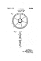
- FIG. 1 is a side elevation of a turbine wheel embodying my invention
- Fig. 2 is a sectional view thereof.
- spokelike reinforcements 3 which, as Will be seen from an inspection of Fig. 1, are disposed at irregular, angular distances from each other and are made of different sizes so as to maintain the position of the center of gravity at the center of the shaft.
- a rotating wheel disk such'as a turbine wheel disk, characterized by the fact that at least one of its surfaces is provided with projections which render non-uniform the distribution of mass in the disk, the distribution of mass being such, however, that the center of gravity is maintained at the center of the disk.
- a rotating wheel disk such as a tur bine wheel disk, characterized by the fact that at least one of its surfaces is provided with radially-extending, spoke-like projections which serve to render non-uniform the distribution of mass in the disk, said projections being so distributed that the center of gravity is maintained at the center of the disk.
Landscapes
- Engineering & Computer Science (AREA)
- Mechanical Engineering (AREA)
- General Engineering & Computer Science (AREA)
- Turbine Rotor Nozzle Sealing (AREA)
Description
- March 31 1925.
- .P; 'MELCHIOR ELASTIC FLUID TURBINE Filed Nov. 4, 1934 His Anzohrtieg- Patented Mar. 31, 1925.
UNITED STATES PATENT oFFIcE.
PAUL MELCHIOR, 0F CHARLOTTZTN'BiaR-G, GERMANY, ASSIGNOR TO ALLGEMEINE ELEKTRIGITATS-GESELLSCHAFT, OF BERLIN, GERMANY.
ELASTIC-FLUID TURBINE.
Application filed. November 4, 1924.
To all whom it may concern:
Be it known that I, PAUL ltlnnornon, a citizen of Germany, residing at Charlottenburg, Dahlmannstrasse 12, Germany. have I invented certain new and useful Improvements in Elastic-Fluid Turbines, of which the following is a specification.
The present invention relates to elastic fluid turbines and especially to turbines of the impulse type wherein the rotor comprises one or more wheels carried by a shaft.
It is now known that rotating wheels, such as, for example, turbine wheels, when subjected periodically to shocks or impacts. as they constitute elastic'bodies, are apt to have vibrations set up in them which travel at right angles to the median plane of symmetry. They then vibrate at very definite frequencies which are denoted as fundamental harmonic vibrations, and to which correspond certain forms of nodal lines.
If the number of impacts or impulses acting upon a wheel per unit of time agrees or substantially agrees with one of these definite frequencies, the vibrations in question become particularly dangerous, for in this case, the nodal waves travel so fast on the wheel disk in a direction opposite to that of rotation that it remains in the shape of a stationary wave with respect to space or to the places from which the impulses start. The deflection of the disk caused by the vibration is then liable to attain proportions such that damage 0r rupture of the disk may occur.
According to the present invention, the foregoing dangerous condition is prevented from occurring by making the lateral faces of the wheel or disk of different shape at different places with the result that the wheel or disk no longer has symmetry of rotation. In this case, the nodal lines are no longer able to travel in the wheel or disk at their own free wills.
In carrying out my invention, I may either add material to or take away material at different places on one or both faces of the disk or wheel, care being taken to ensure that the center of gravity of the disk remains in the middle of the shaft. By this means, the distribution of the mass and the rigidity of the wheel segments becomes nonuniform in the peripheral direction of the wheel.
Serial No. 747,859.
As one specific means of carrying out my invention, I may provide spoke-like reinforcements on one or both sides of the disk or wheel which reinforcements are disposed at irregular, angular distances and are made of such size with relation to one another that the position of the center of gravity remains at the center of the shaft.
In the drawing,Fig. 1 is a side elevation of a turbine wheel embodying my invention, and Fig. 2 is a sectional view thereof. I
Referring to the drawing, 1 indicates the wheel, and 2 the buckets carried by it. On the surface of the wheel on either one or both sides of it there are provided spokelike reinforcements 3 which, as Will be seen from an inspection of Fig. 1, are disposed at irregular, angular distances from each other and are made of different sizes so as to maintain the position of the center of gravity at the center of the shaft.
In accordance with the provisions of the patent statutes, I have described the principle of operation of my invention, together with the apparatus which I now consider to represent. the best embodiment thereof, but I desire to have it understood that the apparatus shown is only illustrative and that the invention may be carried out by other means. i
What I claim as new and desire to secure by Letters Patent of the United States, 1s, I
1. A rotating wheel disk, such'as a turbine wheel disk, characterized by the fact that at least one of its surfaces is provided with projections which render non-uniform the distribution of mass in the disk, the distribution of mass being such, however, that the center of gravity is maintained at the center of the disk.
2. A rotating wheel disk, such as a tur bine wheel disk, characterized by the fact that at least one of its surfaces is provided with radially-extending, spoke-like projections which serve to render non-uniform the distribution of mass in the disk, said projections being so distributed that the center of gravity is maintained at the center of the disk.
In witness whereof, I have hereunto set my hand this 14th,- day of October, 1924.
PAUL LLELCHIOR.
Priority Applications (1)
| Application Number | Priority Date | Filing Date | Title |
|---|---|---|---|
| US747859A US1531968A (en) | 1924-11-04 | 1924-11-04 | Elastic-fluid turbine |
Applications Claiming Priority (1)
| Application Number | Priority Date | Filing Date | Title |
|---|---|---|---|
| US747859A US1531968A (en) | 1924-11-04 | 1924-11-04 | Elastic-fluid turbine |
Publications (1)
| Publication Number | Publication Date |
|---|---|
| US1531968A true US1531968A (en) | 1925-03-31 |
Family
ID=25006944
Family Applications (1)
| Application Number | Title | Priority Date | Filing Date |
|---|---|---|---|
| US747859A Expired - Lifetime US1531968A (en) | 1924-11-04 | 1924-11-04 | Elastic-fluid turbine |
Country Status (1)
| Country | Link |
|---|---|
| US (1) | US1531968A (en) |
Cited By (2)
| Publication number | Priority date | Publication date | Assignee | Title |
|---|---|---|---|---|
| US2888239A (en) * | 1954-03-15 | 1959-05-26 | Chrysler Corp | Turbine wheel construction |
| US2922619A (en) * | 1954-03-15 | 1960-01-26 | Chrysler Corp | Turbine wheel assembly |
-
1924
- 1924-11-04 US US747859A patent/US1531968A/en not_active Expired - Lifetime
Cited By (2)
| Publication number | Priority date | Publication date | Assignee | Title |
|---|---|---|---|---|
| US2888239A (en) * | 1954-03-15 | 1959-05-26 | Chrysler Corp | Turbine wheel construction |
| US2922619A (en) * | 1954-03-15 | 1960-01-26 | Chrysler Corp | Turbine wheel assembly |
Similar Documents
| Publication | Publication Date | Title |
|---|---|---|
| US2916257A (en) | Damping turbine buckets | |
| US1534721A (en) | Construction of elastic-fluid turbines to prevent breakage of blades due to vibrations | |
| Campbell | The protection of steam-turbine disk wheels from axial vibration | |
| US2642263A (en) | Blade apparatus | |
| US2714499A (en) | Blading for turbomachines | |
| US3185441A (en) | Shroud-blading for turbines or compressors | |
| US2347034A (en) | Turbine bucket wheel and the like | |
| US2999669A (en) | Damping apparatus | |
| CN105308266B (en) | rotating body with blades | |
| US1352278A (en) | Elastic-fluid turbine | |
| US1502903A (en) | Steam-turbine rotor and method of avoiding wave phenomena therein | |
| US3572968A (en) | Turbine bucket cover | |
| JP2020060186A (en) | Turbine guide device including guide device with blade | |
| US1531968A (en) | Elastic-fluid turbine | |
| US2948506A (en) | Damping turbine buckets | |
| US1856786A (en) | Bucket wheel and like rotating member | |
| US2809802A (en) | Damping turbine blades | |
| US1534411A (en) | Method and means of counterbalancing crankshafts | |
| US1434414A (en) | Prevention or reduction of vibration in rotating bodies | |
| US2451513A (en) | Oscillation reducing device | |
| Rzadkowski et al. | Multistage Coupling of eight mistuned bladed discs on a solid shaft of the steam turbine, forced vibration analysis | |
| US2255486A (en) | Elastic fluid turbine bucket wheel | |
| US1640788A (en) | Vibration dampener | |
| US1627917A (en) | Vibration dampener | |
| EP3641971B1 (en) | DOUBLE CUTTING DISC WITH CURVED DEFORMATION LINES |