US1531663A - Automobile bed - Google Patents
Automobile bed Download PDFInfo
- Publication number
- US1531663A US1531663A US674948A US67494823A US1531663A US 1531663 A US1531663 A US 1531663A US 674948 A US674948 A US 674948A US 67494823 A US67494823 A US 67494823A US 1531663 A US1531663 A US 1531663A
- Authority
- US
- United States
- Prior art keywords
- seat
- bed
- seats
- bars
- automobile
- Prior art date
- Legal status (The legal status is an assumption and is not a legal conclusion. Google has not performed a legal analysis and makes no representation as to the accuracy of the status listed.)
- Expired - Lifetime
Links
Images
Classifications
-
- B—PERFORMING OPERATIONS; TRANSPORTING
- B60—VEHICLES IN GENERAL
- B60P—VEHICLES ADAPTED FOR LOAD TRANSPORTATION OR TO TRANSPORT, TO CARRY, OR TO COMPRISE SPECIAL LOADS OR OBJECTS
- B60P3/00—Vehicles adapted to transport, to carry or to comprise special loads or objects
- B60P3/32—Vehicles adapted to transport, to carry or to comprise special loads or objects comprising living accommodation for people, e.g. caravans, camping, or like vehicles
- B60P3/36—Auxiliary arrangements; Arrangements of living accommodation; Details
- B60P3/38—Sleeping arrangements, e.g. living or sleeping accommodation on the roof of the vehicle
Definitions
- This invention consists of an automobile bed and has for an object the provision-of 4 suitable mechanism-in an automobile which permits arrangement of the automobile seats into a position where they may be used with facility and expedition as a bed.
- a co-ordinate object of the invention is to a provide incumbersome mechanism which will effectively hold the seats in the desired position, the mechanism being foldable into an inconspicuous position back of the seats when not in use.
- a further object of the invention is to provide mechanism which automatically moves into an operative position when the seats are moved into position for use as a bed and conversely to provide mechanism which automatically moves into an inoperative position when the seats are urged into a normal position in the automobile body.
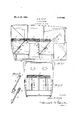
- FIG. 1 is afragmentary longitudinal sectional view of a motor vehicle body illustrating the application of the present invention
- Fig. 2 is a vertical sectional view taken on the line 22 of Fig. 1 looking in the direction of the arrows;
- Fig. 8 is a perspective view of a pair of the bars employed for holding the seats in position as a bed, the bars being shown disconnected.
- an automobile body 4 which may be of standard or any desired construction and in the present instance is shown to be of the touring car type having a front and rear seat.
- the present invention contemplates the employmentof the back 5 of the rear seat, the bottom 6 of the rear seat and the back 7 of the front seat to which latter the metal'covering 8, used under the front seat, is'engaged.
- each bar 9 is rectangular in cross section and is provided at one end with a leaf hinge 11 one of the leaves 12 of which is adapted for securement'to the inner face of the seat back while the opposite leaf is fixedly secured to" the terminal of the bar 9.
- a pair of perforate cars 13 are formed adjacent the opposite end of the bar 9 and are adapted to straddle the bar 10.
- the bar is provided at one end with an inclosed bayonet loop l i in which a pin 15 is adapted to ride.
- the opposite end of the bar 10 is equipped with a hinge 15 one end of which is fixedly secured to'said bar 10 and the opposite end engaged with the rear of the seat frame so as to be hidden from view when the seat back is in its normal position;
- the seat bottom 6 which forms the intermediate part of the bed is positioned between the seat backs 5 and 7 when the latter are in a horizontal position and are supported by the robe rack 17 and bars 9. It will be noted that the hinged leaves 12 of the bars 9 support the front ends of the seat back 5 leaving the other leaf of each hinge'to lie beneath the seat bottom 6.
- Vliat is claimed is 1.
- POTJblODS3- mechanism engage able with the vehicle body and seat portions to retain the latter -in a horizontal position ontop of the seat frames
- @baclis-ano seat frames said bars-beingniovable into a fixed position when thesea-t bacl-Is arenioved to a horizontal plane, to support ...said backs; said barsbeing toldable behind said seat backs when the latter are returned. to their 4101111211 positions.
Landscapes
- Engineering & Computer Science (AREA)
- Health & Medical Sciences (AREA)
- Public Health (AREA)
- Transportation (AREA)
- Mechanical Engineering (AREA)
- Seats For Vehicles (AREA)
Description
Mas-ch 31, 1925. 1,531,663
A. R. KEYE$ AUTOMOBILE BED Filed Nov. 15. 192(3) Patented Mar. 31, 1925.
UNlTED STATES ALLEN R. KEYES, 9F EMIOR-IA, KANSAS.
AUTOBIOBILE BED.
Application filed November 15, 1923. Serial No. 674,948.
To all whom it may concern:
Be it known that I, ALLEN R. KEYEs, a citizen of the United States, residing at Emporia, in the'county of Lyon and State of Kansas, have invented certain new and useful Improvements in Automobile Beds, of which the following is a specification.
This invention consists of an automobile bed and has for an object the provision-of 4 suitable mechanism-in an automobile which permits arrangement of the automobile seats into a position where they may be used with facility and expedition as a bed.
A co-ordinate object of the invention is to a provide incumbersome mechanism which will effectively hold the seats in the desired position, the mechanism being foldable into an inconspicuous position back of the seats when not in use.
A further object of the invention is to provide mechanism which automatically moves into an operative position when the seats are moved into position for use as a bed and conversely to provide mechanism which automatically moves into an inoperative position when the seats are urged into a normal position in the automobile body.
Other objects of the invention will be apparent from the following description of the present preferred form of the invention taken in connection with the accompanying drawings wherein Fig. 1 is afragmentary longitudinal sectional view of a motor vehicle body illustrating the application of the present invention;
Fig. 2 is a vertical sectional view taken on the line 22 of Fig. 1 looking in the direction of the arrows; and
Fig. 8 is a perspective view of a pair of the bars employed for holding the seats in position as a bed, the bars being shown disconnected.
In order to illustrate the application of the present invention an automobile body 4 is shown which may be of standard or any desired construction and in the present instance is shown to be of the touring car type having a front and rear seat. The present invention contemplates the employmentof the back 5 of the rear seat, the bottom 6 of the rear seat and the back 7 of the front seat to which latter the metal'covering 8, used under the front seat, is'engaged.
When it is desired to convert the seats of the automobile body into a bed, as illustrated in Figs. 1 and 2, the backs 5 and 7 of the vehicle seats are swung upwardly into a horizontal position so as to rest on top of the upper margins of the seat frames. The backs are held'in position by suitable mechanism which in the present instance consists of inter-connected bars 9 and 10. Each bar 9 is rectangular in cross section and is provided at one end with a leaf hinge 11 one of the leaves 12 of which is adapted for securement'to the inner face of the seat back while the opposite leaf is fixedly secured to" the terminal of the bar 9. A pair of perforate cars 13 are formed adjacent the opposite end of the bar 9 and are adapted to straddle the bar 10. The bar is provided at one end with an inclosed bayonet loop l i in which a pin 15 is adapted to ride. The opposite end of the bar 10 is equipped with a hinge 15 one end of which is fixedly secured to'said bar 10 and the opposite end engaged with the rear of the seat frame so as to be hidden from view when the seat back is in its normal position; Upon reference to Fig. 1 of the drawings it will be apparent that when the seat backs are in a horizontal position the pin 15 lies in the inner end of the bayonet loop 14, whereas when the seat back is-to be folded into its normal position the end thereof, which is engaged by the bar 9, is first moved upwardly until the pin 15 moves into the outer end of the bayonet groove after which the back is permitted to gravitate into its normal posi tion. This causes the bars 9 and 10 to be folded together and move into a compartment 16 formed in the back of each seat frame. In this way, the'bars 9 and 10 will not be exposed to view when the seat backs are in a normal position. The seat bottom 6 which forms the intermediate part of the bed is positioned between the seat backs 5 and 7 when the latter are in a horizontal position and are supported by the robe rack 17 and bars 9. It will be noted that the hinged leaves 12 of the bars 9 support the front ends of the seat back 5 leaving the other leaf of each hinge'to lie beneath the seat bottom 6. I I
The bars 9 which'are mounted in the front seat of the vehicle have the upper ends thereof hingedly or otherwise connected to the metal cover 8 the latter being adapted for engagement with the steering wheel 18 of the Vehicle and capaoitating as a head rest upon which a pillow=-or the illkQ'blllZtY be positioned.
interconnected bars engaged with the seat From the above it is apparent that the seats of the vehicle may be convertedinto. a bed With facility and expedity Without resorting to the use oi accessories. The con struction is such that a rigid yet comforter ble bed is provided Wlri'olriavill:ably Withi-y stand the strain'iinposed thereon. Mfloreover, the IHQCllZlRlSlllillSLd for supportingtne portions: of ztllBzSGfli): nrpositionas nsed as a b6difl1111f0lllbl6280 as-to occupy a minimum amonntnofi space wheirnot in use, and thebed isn't a SUiilOlell'LuelGVfliLlOIl tO ac connnodatei 1 and. other paraphernalia therebeneath:
Varrousaehanges .inay be made n th1s=de- Viceuespecially; inuthe. details not constr-uo tioirrmionortion .xand iarran 'einent of arts 7 .L n b Within ;thescope ot t'he olaiins hereto appended. Y
Vliat is claimed is 1. In combination with a vehicle body in-= eluding seats with unovable seat POTJblODS3- mechanism engage able with the vehicle body and seat portions to retain the latter -in a horizontal position ontop of the seat frames,
for use as a bed including.
@baclis-ano seat frames said bars-beingniovable into a fixed position when thesea-t bacl-Is arenioved to a horizontal plane, to support ...said backs; said barsbeing toldable behind said seat backs when the latter are returned. to their 4101111211 positions.
3. in combination with an automobilebodyl inol udingni ron backs and bottoms movable independently or the seattranies, ineohanisinato'support-said -i oldable to lie he movable backbaoksand one ofi said bottoms in a llOliZr Zontal plane :011: tooot the seat-ira neto provide a supportin ctnre Without ;al-
term 9" k 3 il the seat bael s' when the latter arein their no bl positions on the seat trainee.
i. In: combination t with; an "automobile body including trainee-equipped' with 'andbottom cushion parts," and a steering Wheel; interconnected bars hing 'edly mounted on ealn'seat tran1e,-and noranally concealed =b nnd the back cushion =0 fr. 1f lna i 1 V each seat, ioi supp-oi ting saio euslnon )ai is,
in COIljUHCilOir with the' tops of the seat frames, in a horizontal plane'on-top-otsaid trainee, and ineans conneeted to oneot said cushion parts and resting upon said s eor- 111g; heel to serve as a head rest.
In testimonywhereofI at I i-nay signature ALLEN nd rear seats havinn' id trainee, said mechanism
Priority Applications (1)
| Application Number | Priority Date | Filing Date | Title |
|---|---|---|---|
| US674948A US1531663A (en) | 1923-11-15 | 1923-11-15 | Automobile bed |
Applications Claiming Priority (1)
| Application Number | Priority Date | Filing Date | Title |
|---|---|---|---|
| US674948A US1531663A (en) | 1923-11-15 | 1923-11-15 | Automobile bed |
Publications (1)
| Publication Number | Publication Date |
|---|---|
| US1531663A true US1531663A (en) | 1925-03-31 |
Family
ID=24708506
Family Applications (1)
| Application Number | Title | Priority Date | Filing Date |
|---|---|---|---|
| US674948A Expired - Lifetime US1531663A (en) | 1923-11-15 | 1923-11-15 | Automobile bed |
Country Status (1)
| Country | Link |
|---|---|
| US (1) | US1531663A (en) |
-
1923
- 1923-11-15 US US674948A patent/US1531663A/en not_active Expired - Lifetime
Similar Documents
| Publication | Publication Date | Title |
|---|---|---|
| US1548334A (en) | Automobile seat bed | |
| US1200852A (en) | Ambulance-trailer body. | |
| US1531663A (en) | Automobile bed | |
| US1527105A (en) | Camping outfit | |
| US1333924A (en) | Folding bed for automobiles | |
| US1599588A (en) | Convertible seat, berth, and table for automobiles and like vehicles | |
| US1315031A (en) | Planooraph co | |
| US1369150A (en) | Convertible seat for automobiles | |
| US1609113A (en) | Automobile bed | |
| US1715308A (en) | Automobile bed | |
| US1722916A (en) | Automobile tourist bed | |
| US1620346A (en) | Automobile bed | |
| US1620433A (en) | Cot for automobiles | |
| US1905605A (en) | Automobile bed | |
| US1584545A (en) | Convertible body for vehicles | |
| US1873525A (en) | Seat construction for sedan type automobiles | |
| US1273977A (en) | Automobile-body. | |
| US1289477A (en) | Baby-carriage seat. | |
| US745108A (en) | Combination cutunder carriage. | |
| US1358784A (en) | Convertible vehicle-body | |
| US1146849A (en) | Seat arrangement for automobiles. | |
| US1768466A (en) | Rumble seat | |
| GB1236647A (en) | Seating in powered vehicles | |
| US1977520A (en) | Automobile combined seat and bed | |
| US3032779A (en) | Play pen or crib accessory for automobiles |