US1528362A - Electrical distribution system - Google Patents
Electrical distribution system Download PDFInfo
- Publication number
- US1528362A US1528362A US717885A US71788524A US1528362A US 1528362 A US1528362 A US 1528362A US 717885 A US717885 A US 717885A US 71788524 A US71788524 A US 71788524A US 1528362 A US1528362 A US 1528362A
- Authority
- US
- United States
- Prior art keywords
- feeders
- station
- supply
- sub
- feeder
- Prior art date
- Legal status (The legal status is an assumption and is not a legal conclusion. Google has not performed a legal analysis and makes no representation as to the accuracy of the status listed.)
- Expired - Lifetime
Links
- 238000009826 distribution Methods 0.000 title description 16
- 230000001681 protective effect Effects 0.000 description 19
- 238000004804 winding Methods 0.000 description 8
- 230000002633 protecting effect Effects 0.000 description 3
- 230000004048 modification Effects 0.000 description 2
- 238000012986 modification Methods 0.000 description 2
- 238000010276 construction Methods 0.000 description 1
- 230000006872 improvement Effects 0.000 description 1
- 229920000136 polysorbate Polymers 0.000 description 1
Images

Classifications
-
- H—ELECTRICITY
- H02—GENERATION; CONVERSION OR DISTRIBUTION OF ELECTRIC POWER
- H02H—EMERGENCY PROTECTIVE CIRCUIT ARRANGEMENTS
- H02H7/00—Emergency protective circuit arrangements specially adapted for specific types of electric machines or apparatus or for sectionalised protection of cable or line systems, and effecting automatic switching in the event of an undesired change from normal working conditions
- H02H7/26—Sectionalised protection of cable or line systems, e.g. for disconnecting a section on which a short-circuit, earth fault, or arc discharge has occured
- H02H7/266—Sectionalised protection of cable or line systems, e.g. for disconnecting a section on which a short-circuit, earth fault, or arc discharge has occured involving switching on a spare supply
Definitions
- This invention relates to electric distribution systems and has particular reference to an arrangement of switch gear at a duplicate supply sub-station connected to a high tension net work.
- the object of the present invention is to give a more secure duplicate supply to a substation with a minimum amount of high tension switch gear thus reducing the cost and avoiding complication, and also improve the general security of the whole system.
- high tension bus bars are dispensed with and the two feeders are connected together through a high tension switch or circuit breaker and are also connected either directly or through fuses or switches of comparatively low rupturing capacity to one or more transformers.
- a duplicate low tension supply from the sub-station is required,
- each feeder is connected to one of the transformers, whilst when a duplicate high tension supply only is required.
- a single transformer may be employed to which the two feeders are connected through achange-over switch.
- each feeder comes from an adjacentand similarly arranged sub-station with one or two transformers, and each feeder section is provided with protective gear for example of the balanced type, the high tension circuit breaker which may be the only circuit breaker of large rupturing capacity in the sub-station) conveniently being included in the protection by overlapping the protective gear.
- the improved arrangement not only reduces the number of high tension circuit breakers necessary for each sub-station but also makes the application of the protective gear more simple than in usual arrangements and enab es the protective gear to embrace the whole of the apparatus so that any fault whatever will be cleared at the substation on either side and thus limit the interruption to the one substation affected.
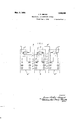
- Figure 1 shows an arrangement giving duplicate high tension and low tension su plies
- FIGS. 2 and 3 show arrangements in which a duplicate high tension supply only is employed.
- the substation A is supplied with high tension current through the two feeders B B coming from adjacent similarly arranged substations A A
- the two feeders B B are connected together through the high tension circuit breaker C and are also respectively connected through fuses D D to two transformers E E.
- Low tension circuit breakers F F are also provided in the low tension supply circuits from the transformers E E.
- Each feeder section B (or B) is provided with balanced protective gear, the pilot circuit L (or in each case being controlled by two current transformers in the substation A and by two similarly arrangedtransformers in the substation A (or A at the other end of the feeder section in question.
- the primary winding of one of these two transformers is disposed, as indicated at G (or G) between the fuse D (or D) and the transformer E (or E) in the circuit adjacent to the protected feeder section, whilst the other primary winding is disposed, as indicated at H (or H) on the side of the high tension circuit breaker C remote from the protected section.
- the feeder B is protected by means of a pilot circuit L controlled from thetwo current transformers G H in the substation A and two corresponding current transformers G H in thesubstation A, the
- the feeder B has similar protection, which also includes the circuit breaker G and the fuse D, the pilot circuit L in this case being controlled from the two current transformers G H and the corresponding current transformers G H? in the substation AP.
- Any suitable type of balanced protective gear such for exaple as the Mer'z-Price type, may be employed.
- FIG 2 the general arrangement is similar to that of Figure 1 with the exception that a single transformer E is cmployed in place of the two transformers E E, this transformer E being connected through a changeover switch J to one or other of its two contacts J or J and thence to the feeder B or B through the fuse D or D.
- the protective gear (of which the secoiidai'y' circuiti's o mitted for the sake of c'l'e'ar'ness) is also arranged as'in Figure l, the two primary windings at G G being disposed between the change-over switch J and the fuses D D respectively.
- the secondary winding G for this primary G is,however, connected up only to one'of the two pilot circuits L L a change-over switch K being provided to determiueto which pilot circuit this secondary G is to be connected.
- the switch K has two separate pairs of arms K K of which the pair K serves to connect the secondary G with one or other of the two pilot circuits L (or L whilst the pair K acts to close the pilot circuit L (or L to which the secondary G is not connected.
- the switch K is preferably mechanically interlocked'with the switch J, so that the two switches move together, the arrangement being such that the secondary winding G is always connected into the pilot circuit pro tecting the feeder section to which the trans former E is connected through the main change-over switch J.
- the switch J is :closed on its right-hand contact J so that the transformer 2 is connected directly to the feeder B.
- the secondary G is connected through the pair K ofswitch arms into the pilot circuit L protecting the feeder B. whilst the pair K of switch arms serves to close the pilot circuit L protecting the feeder B. If new he switch J is thrown over on to its lefthand' contact J, the switch K is also thrown over onto its left-hand contacts, so that the secondary G is now connected into the pilot closed by the switch arms F With this arrangement the fuse D and the main circuit breaker C are again included in the protection.
- substations A A on either side of the substation A have been shown arranged in exactly the same manner as the substation A. It will be understood, however, that the adjacent substations may be arranged in other ways. For instance, a substation A having a single transformer as shown in Figure 2 or Figure 3 may be disposed between two substations, either or each of which has duplicate transformers E E as shown in Fig ure 1, and vice versa.
- An arrangement of circuits for a dupli cate supply sub-station in an electric distribution system including in combination two feeders from which the sub-station is supplied with power, a high tension circuit breaker disposed between and connecting the two feeders, and at least one transformer connected to the two feeders and from which the low tension supply is drawn.
- An arrangement of circuits for a duplicate supply sub-station in an electric distribution system including in combination two feeders from which the sub-station is supplied with power, a high tension circuit breaker disposed between and connecting the two feeders, at least one transformer connected to the two feeders and from which the low tension supply is drawn and at least one fuse of comparatively low rupturing capacity disposed between each transformer and the feeders.
- An arrangement of circuits for a duplicate supply sub-station in an electric distribution system including in combination two feeders from which the sub-station is supplied with power, a high tension circuit breaker disposed between and connecting the two feeders, a single transformer from which the low tension supply is drawn, and means for connecting this transformer to either of the two feeders.
- An arrangement of circuits for a duplicate supply sub-station in an electric distribution system including in combination two feeders from which the sub-station is supplied with power, a high tension circuit breaker disposed between and connecting the two feeders, a single transformer from which the low tension supply is drawn, a changeover switch whose position detertermines to which feeder the transformer is connected, and at least one fuse of comparatively low rupturing capacity disposed bc tween the transformer and the two feeders.
- An arrangement of circuits for a luplicate supply sub-station in an electric distribution system including in combination two feeders from which the sub-station is supplied with power, a high tension circuit breaker disposed between and connecting the two feeders, at least one transformer connected to the two feeders and from which the low tension supply is drawn and electric protective gear for each feeder.
- An arrangement of circuits for a dupli cate supply sub-station in an electric distribution system including in combination two feeders from which the sub-station is supplied with power, a high tension circuit breaker disposed between and connecting the two feeders, at least one transformer connected to the two feeders and from which the low tension supply is drawn and electric protective gear of the balanced type for each feeder so arranged as to include the high tension circuit breaker within each protected section.
- An arrangement of circuits for a duplicate supply sub-station in an electric distribution system including in combination two feeders from which the sub-station is supplied with power, a high tension circuit breaker disposed between and connecting the two feeders, at least one transformer connected to the two feeders and from which the low tension supply is drawn, at least one fuse of comparatively low rupturing capac ity disposed between each transformer and the feeders and electric protective gear for each feeder so arranged as to include the high tension circuit breaker and a fuse with in each protected section.
- An arrangement of circuits for a duplicate supply sub-station in an electric 'distribut-ion system including in combination two feeders from which the sub-station is supplied with power and which each connect the substation with an adjacent substation, a high tension circuit breaker disposed between and connecting the two feeders, at last one transformer connected to the two feeders and from which the low tension supply is drawn and electric protective gear of the balanced type for each feeder.
- An arrangement of circuits for a duplicate supply sub-station in an electric distribution system including in combination two feeders from which the sub-station is supplied with power, a high tension circuit breaker disposed between and connecting the two feeders, a single transformer from which the low tension supply is drawn, meansfor connecting this transformer to either of the two feeders and electric protective gear for each feeder so arranged as to include the high tension circuit breaker within each protected section.
- An arrangement-of circuits for a duplicate supply sub-station in an electric distribution system including in combination two feeders from which the sub-station is supplied with power, a high tension circuit breaker disposed between and connecting the two feeders, a single transformer from which the low tension supply is drawn, a change-over switch whose position determines to which feeder the transformer is connected, at least one fuse of comparatively low rupturing capacity disposed between the transformer and the two feeders, electric protective gear of the balanced type for each feeder, and a switch controlling the secondary circuits of such protective gear.
Landscapes
- Supply And Distribution Of Alternating Current (AREA)
Description
' J. R. BEARD ELECTRICAL DISTRIBUTION SYSTEMS Filed June 4. 1924 2 Sheets-Sheet 1 Mar. 3, 1925.
J. R. BEARD ELECTRICAL DISTRIBUTION sYsT-zsas Filed June 4, 1924 2 Sheets-Sheet 2 mirzwrazp Patented Mar. 3, 1925.
UNITED STATES PATENT OFFICE.
JAMES ROBERT BEARD, OF LONDON. ENGLAND, ASSIGNOR TO ELECTRICAL IMPROVE- MENT$ LIMITED. 03' NE'WGASTLE-UPON-TYIIE, ENGLAND. A BRITISH COMPANY.
ELECTRICAL DISTRIBUTION SYSTEM.
Application filed June 4, 1924. Serial No. 717,885.
To all wiz am it may concern Be it known that I. Janus Ronnu'r BEARD.
a. subject of the King of England, and residing at London, in England, have invented 5 certain new and useful Improvements in Electric Distribution Systems, of which the following as a specification.
This invention relates to electric distribution systems and has particular reference to an arrangement of switch gear at a duplicate supply sub-station connected to a high tension net work.
To aflord adequate protection to such a sub-station it is usual to provide a high tension bus barat the station fed from two high tension feeders and to take the power from the bus bar through two transformers. According to modern practice, in such an arrangement at least four high tension circuit breakers would be used one between each of the feeders and the bus bar and one between the bus bar and each of the transformers. In many cases a fifth switch or circuit breaker would be placed in the bus bar between the two feeding points in order that a fault on the bus bar circuit may be cleared without interrupting the supply to the substation and that the apparatus on either side may be repaired or maintained without interference with the other side.
With such an arrangement a reasonably reliable duplicate supply can be assured provided that the single high tension bus bar remains healthy but the cost of the switch gear is considerable. Further, if the bus bar breaks down, not only is the supply to the particular sub-station interfered with but the supply to other sub-stations on the same net work may also fail.
The object of the present invention is to give a more secure duplicate supply to a substation with a minimum amount of high tension switch gear thus reducing the cost and avoiding complication, and also improve the general security of the whole system.
According to this invention high tension bus bars are dispensed with and the two feeders are connected together through a high tension switch or circuit breaker and are also connected either directly or through fuses or switches of comparatively low rupturing capacity to one or more transformers. In cases where a duplicate low tension supply from the sub-station is required,
two transformers are employed, and each feeder is connected to one of the transformers, whilst when a duplicate high tension supply only is required. a single transformer may be employed to which the two feeders are connected through achange-over switch.
Preferably each feeder comes from an adjacentand similarly arranged sub-station with one or two transformers, and each feeder section is provided with protective gear for example of the balanced type, the high tension circuit breaker which may be the only circuit breaker of large rupturing capacity in the sub-station) conveniently being included in the protection by overlapping the protective gear.
The improved arrangement not only reduces the number of high tension circuit breakers necessary for each sub-station but also makes the application of the protective gear more simple than in usual arrangements and enab es the protective gear to embrace the whole of the apparatus so that any fault whatever will be cleared at the substation on either side and thus limit the interruption to the one substation affected.
The invention may be carried into prac tice in various ways but the accompanying drawings illustrate diagrammatically by way of example some preferred arrangements according thereto. In these drawings,-
Figure 1 shows an arrangement giving duplicate high tension and low tension su plies, and
Figures 2 and 3 show arrangements in which a duplicate high tension supply only is employed.
Like reference letters indicate like parts in the various figures.
In the arrangement shown in Figure 1, the substation A is supplied with high tension current through the two feeders B B coming from adjacent similarly arranged substations A A The two feeders B B are connected together through the high tension circuit breaker C and are also respectively connected through fuses D D to two transformers E E. Low tension circuit breakers F F are also provided in the low tension supply circuits from the transformers E E.
Each feeder section B (or B) is provided with balanced protective gear, the pilot circuit L (or in each case being controlled by two current transformers in the substation A and by two similarly arrangedtransformers in the substation A (or A at the other end of the feeder section in question. The primary winding of one of these two transformers is disposed, as indicated at G (or G) between the fuse D (or D) and the transformer E (or E) in the circuit adjacent to the protected feeder section, whilst the other primary winding is disposed, as indicated at H (or H) on the side of the high tension circuit breaker C remote from the protected section. Thus the feeder B is protected by means of a pilot circuit L controlled from thetwo current transformers G H in the substation A and two corresponding current transformers G H in thesubstation A, the
circuit breaker C and the fuse D together with the corresponding circuit breaker and fuse in the substation A being included withinthe protection. The feeder B has similar protection, which also includes the circuit breaker G and the fuse D, the pilot circuit L in this case being controlled from the two current transformers G H and the corresponding current transformers G H? in the substation AP. Any suitable type of balanced protective gear, such for exaple as the Mer'z-Price type, may be employed.
lVit'h this arrangementboth transformers will normally be in service and a duplicate low tension supply is'thus provided. If one of the feeders, say the feeder B, breaks down, the protective gear controlled by the current transformers G H G H will operate to cut out the faulty feeder B, but the low tension supply will be maintained through the feeder B and the transformer E.
In some cases it is unnecessary to provide a duplicate low'ten'sion' supply, and Figures 2 and 3 show alternative arrangements for such cases.
In Figure 2 the general arrangement is similar to that of Figure 1 with the exception that a single transformer E is cmployed in place of the two transformers E E, this transformer E being connected through a changeover switch J to one or other of its two contacts J or J and thence to the feeder B or B through the fuse D or D. The protective gear (of which the secoiidai'y' circuiti's o mitted for the sake of c'l'e'ar'ness) is also arranged as'in Figure l, the two primary windings at G G being disposed between the change-over switch J and the fuses D D respectively.
With this arrangement only one fuse D or D is normally in service according'to the position of 'the change-ovcr switch J Thus if fault occurs in the feeder B, when the switch-J is closed on its contact J. the protective gear between G H G H will opcrate to cut out the faulty feeder B, but the supply to the sub-station A will be maintained through the feeder B. If however a fault occurs in the feeder B when the switch J is closed on its contact J the supply to the sub-station will be completely interrupted by the operation of theprotective gear betweei'iGJ-I G H Supply can be resumed however up to full capacity by throwing over the switch J on to its other contact J This may be effected automatically, if desired, from the failure of the consumcrs supply. The failure of the single transformer completely interrupts the low tension supply from the sub-station A.
The arrangement shown in Figure 3 only dilfers from that of Figure 2, as far as the main circuit is concerned, in that only one fuse D is employed, the change-over switch J being disposed between this fuse D and the two feeders B B. Some modification of the balanced protective gear is however necessary with this arrangement, and the pilot circuits L L are therefore shown in this figure. The two current transformer primary windings H H one on eachside of the high tension circuit breakcrC are again employed as in the arrangement of Figure 2, but the other two primary windings G G are in this case replaced by a single transformer primary winding G which is common to the two protective gears for the feeder sections B and B. The secondary winding G for this primary G is,however, connected up only to one'of the two pilot circuits L L a change-over switch K being provided to determiueto which pilot circuit this secondary G is to be connected. The switch K has two separate pairs of arms K K of which the pair K serves to connect the secondary G with one or other of the two pilot circuits L (or L whilst the pair K acts to close the pilot circuit L (or L to which the secondary G is not connected. The switch K is preferably mechanically interlocked'with the switch J, so that the two switches move together, the arrangement being such that the secondary winding G is always connected into the pilot circuit pro tecting the feeder section to which the trans former E is connected through the main change-over switch J. Thus in the position shown in the figure the switch J is :closed on its right-hand contact J so that the transformer 2 is connected directly to the feeder B. The secondary G is connected through the pair K ofswitch arms into the pilot circuit L protecting the feeder B. whilst the pair K of switch arms serves to close the pilot circuit L protecting the feeder B. If new he switch J is thrown over on to its lefthand' contact J, the switch K isalso thrown over onto its left-hand contacts, so that the secondary G is now connected into the pilot closed by the switch arms F With this arrangement the fuse D and the main circuit breaker C are again included in the protection.
This arrangement operates in exactly the same manner as the arrangement of Figure 2 with the exception that, when the changeover switch J is thrown over to resume the supply after it has been cut off by the operation of the protective gear, the switch K in the pilot circuits is also thrown over, thus ensuring that the fuse D is always included in the protection. With this arrangement also the switch J may be operated automatically by the failure of the consumers supply from the sub-station.
In all the constructions illustrated the substations A A on either side of the substation A have been shown arranged in exactly the same manner as the substation A. It will be understood, however, that the adjacent substations may be arranged in other ways. For instance, a substation A having a single transformer as shown in Figure 2 or Figure 3 may be disposed between two substations, either or each of which has duplicate transformers E E as shown in Fig ure 1, and vice versa.
The arrangements described and illustrated have been given by w y of example only and modifications may be made without departing from the scope of the invention.
hat I claim as my invention and desire to secure by Letters Patent is 1. An arrangement of circuits for a dupli cate supply sub-station in an electric distribution system, including in combination two feeders from which the sub-station is supplied with power, a high tension circuit breaker disposed between and connecting the two feeders, and at least one transformer connected to the two feeders and from which the low tension supply is drawn.
2. An arrangement of circuits for a duplicate supply sub-station in an electric distribution system, including in combination two feeders from which the sub-station is supplied with power, a high tension circuit breaker disposed between and connecting the two feeders, at least one transformer connected to the two feeders and from which the low tension supply is drawn and at least one fuse of comparatively low rupturing capacity disposed between each transformer and the feeders.
3. An arrangement of circuits for a duplicate supply sub-station in an electric distribution system, including in combination two feeders from which the sub-station is supplied with power, a high tension circuit breaker disposed between and connecting the two feeders, a single transformer from which the low tension supply is drawn, and means for connecting this transformer to either of the two feeders.
t. An arrangement of circuits for a duplicate supply sub-station in an electric distribution system, including in combination two feeders from which the sub-station is supplied with power, a high tension circuit breaker disposed between and connecting the two feeders, a single transformer from which the low tension supply is drawn, a changeover switch whose position detertermines to which feeder the transformer is connected, and at least one fuse of comparatively low rupturing capacity disposed bc tween the transformer and the two feeders.
5. An arrangement of circuits for a luplicate supply sub-station in an electric distribution system, including in combination two feeders from which the sub-station is supplied with power, a high tension circuit breaker disposed between and connecting the two feeders, at least one transformer connected to the two feeders and from which the low tension supply is drawn and electric protective gear for each feeder.
6. An arrangement of circuits for a dupli cate supply sub-station in an electric distribution system, including in combination two feeders from which the sub-station is supplied with power, a high tension circuit breaker disposed between and connecting the two feeders, at least one transformer connected to the two feeders and from which the low tension supply is drawn and electric protective gear of the balanced type for each feeder so arranged as to include the high tension circuit breaker within each protected section.
7 An arrangement of circuits for a duplicate supply sub-station in an electric distribution system, including in combination two feeders from which the sub-station is supplied with power, a high tension circuit breaker disposed between and connecting the two feeders, at least one transformer connected to the two feeders and from which the low tension supply is drawn, at least one fuse of comparatively low rupturing capac ity disposed between each transformer and the feeders and electric protective gear for each feeder so arranged as to include the high tension circuit breaker and a fuse with in each protected section.
8. An arrangement of circuits for a duplicate supply sub-station in an electric 'distribut-ion system, including in combination two feeders from which the sub-station is supplied with power and which each connect the substation with an adjacent substation, a high tension circuit breaker disposed between and connecting the two feeders, at last one transformer connected to the two feeders and from which the low tension supply is drawn and electric protective gear of the balanced type for each feeder.
9. An arrangement of circuits for a duplicate supply sub-station in an electric distribution system, including in combination two feeders from which the sub-station is supplied with power, a high tension circuit breaker disposed between and connecting the two feeders, a single transformer from which the low tension supply is drawn, meansfor connecting this transformer to either of the two feeders and electric protective gear for each feeder so arranged as to include the high tension circuit breaker within each protected section.
10. An arrangement-of circuits for a duplicate supply sub-station in an electric distribution system, including in combination two feeders from which the sub-station is supplied with power, a high tension circuit breaker disposed between and connecting the two feeders, a single transformer from which the low tension supply is drawn, a change-over switch whose position determines to which feeder the transformer is connected, at least one fuse of comparatively low rupturing capacity disposed between the transformer and the two feeders, electric protective gear of the balanced type for each feeder, and a switch controlling the secondary circuits of such protective gear.
In testimony whereof I have signed my name to this specification.
JAMES ROBERT BEARD.
Priority Applications (1)
| Application Number | Priority Date | Filing Date | Title |
|---|---|---|---|
| US717885A US1528362A (en) | 1924-06-04 | 1924-06-04 | Electrical distribution system |
Applications Claiming Priority (1)
| Application Number | Priority Date | Filing Date | Title |
|---|---|---|---|
| US717885A US1528362A (en) | 1924-06-04 | 1924-06-04 | Electrical distribution system |
Publications (1)
| Publication Number | Publication Date |
|---|---|
| US1528362A true US1528362A (en) | 1925-03-03 |
Family
ID=24883883
Family Applications (1)
| Application Number | Title | Priority Date | Filing Date |
|---|---|---|---|
| US717885A Expired - Lifetime US1528362A (en) | 1924-06-04 | 1924-06-04 | Electrical distribution system |
Country Status (1)
| Country | Link |
|---|---|
| US (1) | US1528362A (en) |
-
1924
- 1924-06-04 US US717885A patent/US1528362A/en not_active Expired - Lifetime
Similar Documents
| Publication | Publication Date | Title |
|---|---|---|
| US2209810A (en) | Protection of electric systems | |
| US1528362A (en) | Electrical distribution system | |
| US2306226A (en) | High voltage power transmission | |
| US1871724A (en) | Multifrequency circuit breaker control system and protective system | |
| US1652559A (en) | Protective relay system | |
| US2928995A (en) | Protective means for series capacitors on power lines | |
| US1884444A (en) | Transmission line protective system | |
| US2324451A (en) | Current protective means | |
| US1705687A (en) | Relay system | |
| GB221322A (en) | Improvements in or relating to electric distribution systems | |
| US1023377A (en) | Automatic sectionalizing device. | |
| US1717240A (en) | Protective arrangement | |
| US1295885A (en) | Relay system. | |
| US1798690A (en) | Protective system | |
| US1707269A (en) | Electrical distribution system | |
| US1837033A (en) | Protective relay system using reactors | |
| US1333892A (en) | ackerman | |
| US2246310A (en) | Current-polarized ground-directional relay for parallel lines | |
| US1693402A (en) | Relay system | |
| US2173673A (en) | Electric distribution system | |
| GB172731A (en) | Improvements in and relating to electric power distribution systems | |
| US771891A (en) | Protective system for electric conductors. | |
| US1624729A (en) | Power system | |
| US1896943A (en) | Selective circuit protecting device | |
| US1870784A (en) | Alternating current distribution system |