US1521663A - Drying gabinet - Google Patents
Drying gabinet Download PDFInfo
- Publication number
- US1521663A US1521663A US679191A US67919123A US1521663A US 1521663 A US1521663 A US 1521663A US 679191 A US679191 A US 679191A US 67919123 A US67919123 A US 67919123A US 1521663 A US1521663 A US 1521663A
- Authority
- US
- United States
- Prior art keywords
- casing
- cabinet
- drying
- rack
- burners
- Prior art date
- Legal status (The legal status is an assumption and is not a legal conclusion. Google has not performed a legal analysis and makes no representation as to the accuracy of the status listed.)
- Expired - Lifetime
Links
Images
Classifications
-
- F—MECHANICAL ENGINEERING; LIGHTING; HEATING; WEAPONS; BLASTING
- F26—DRYING
- F26B—DRYING SOLID MATERIALS OR OBJECTS BY REMOVING LIQUID THEREFROM
- F26B9/00—Machines or apparatus for drying solid materials or objects at rest or with only local agitation; Domestic airing cupboards
- F26B9/06—Machines or apparatus for drying solid materials or objects at rest or with only local agitation; Domestic airing cupboards in stationary drums or chambers
Definitions
- Another object of the invention 1 s the provision of a novel form of drying rack
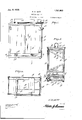
- z- Figure 1 is a front elevation of a cabinet constructed in accordance with the invention, the doors of the cabinet being closed.
- Figure 2 l is a similar view with the doors open.
- Figure 3 is a section on the line 3-3 of Figure 1.
- v Figure 4 is a similar view on the line 4-4 of Figure 1.
- Figure 5 is a section on the line 5 5 of Fgure 3.
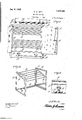
- FIG. 6 is a detail perspective view of the dryingI rack.
- the cabinet is shown as comprising a casing lO which is open at time ' the front and which is adapted to be closed* by'means of hingedly mounted doors 11.
- These doors ha ve theirfree edges overlap-g ping and one of Jthe doors is provided with upper and lower oppositely movable connected to a handle the bolts or latches and ,the doors opened and closed.
- the bottom of the cabinetf 10 has spaced 13, by means of which upwardly therefrom a false or supplemental bottom 14 which is provided with spaced pcrforations and whichis located substantially on a line -with the lower edge of vtheas to provide between this door opening so supplemental bottom and the bottom of the casing 10, a burner compartment 15.
- EX- tending into this compartment [15 are 'boltsfor latches 12 which are operatively may be manipulated l burners A16, whose inner ends are supported upon a bar17, while located above each of the burners beneath the supplemental bot-v tom 14 are battle or heat distributing plates 17.
- Fuel preferably gas is supplied to the sion 19 for connection with a suitable source n yburners through a pipe 18 having an extenlVith the above and other objects in view,.-
- the top of the cabinet 10 is provided with I outlet openings from which extend vshort pipe sections 22, the latter being connected by means ⁇ of a pipe 23 which is preferably flattened to reduce the height of the cabinet.
- One end of the pipe 23 is provided with a removable cap 24: while its opposite end is provided-with a removable section 25 in 21 by means of which the degree of heat may be accuratelyl regumovable frame.
- 3() having a screen cover vided with a baffle plate or false.
- top 27 having perforations therein so that direct draft through the pipes Q2 is prevented and the lation of the heat waves upward throughout the entire area. of the. drier, which circulation acts to thoroughly dry the clothes while the hot air tends to whiten or bleach them.
- the front of the casing is yprovided with transparent covered openings Q8 which are located above valves '129 which control the burners.
- Thisframe Located within the. cas-ing and spaced above the supplemental bottom l-.i is a re- 3l. Thisframe is positioned directly above the bottom la and acts to protect articles within the casing by preventing their contact with the bottom 14.
- a rack 32 which is ⁇ formed of spacedi rectangular frames 33, the latter including oppositely inclined upper and lower bars 34. These bars are connected by rods 35 which actto support the articles to be dried.
- the rack 82 is slidingly mounted within for this purposeithe opposite walls of the latter are provided with upper and lower horizontally arranged ribs-36 which receive the frames' between them.
- the upper ribs are provided With stops 23T to limit the outward movement of the rack.
- a drying cabinet embodying a casing open at the front and provided with an outlet at the top thereof, doors for the front of the casing, a supplemental bottom. having openings therein and spaced from the casing bottom to define a yburner compartment, burners in said-compartment, heat. distributing plates located within the burner compartment over the burners, a dryin v rack, a'valve for controlling the outlet in lie 00p the cabinet and i of the casing and a perforated baffle plate in the top of the cabinet.
- a drying cabinet embodying a casing open at the front, doors for closing the casing, a supplemental bottom having openings therein and spaced from the casing bottom to define a burner compartnient ⁇ burners in said compartment, heat distributing plates located within the burner compartment over the burners.
- a drying rack spaced outlet pi pes extending from the top of the cabinet, a. pipe connecting the outer ends of the outlet pipes, a damper located within the connecting pipe and regulating the draft through the cabinet and a perforated baffle plate in the top of the cabinet.
- a drying cabinet embodying a casing open at the front and providedwith an outlet in the top thereof, doors for closing the p front of the casing, a supplemental bottom having openings therein and spaced from the casing bottom to define a burner compartment, burners in said compartment, heat distributing plates located within the burner compartment over the burners, a drying rack, and a horizontally disposed screen located between the rack and spaced above the supplemental bottom.
- a .drying cabinet embodying a casing open at thel front, doors for the casing, a source of heat at the bottom of the casing, an .outlet at the top of said casing, a drying rack, said rack comprising substantially rectangular end frames, upper and lower spaced rods connecting the frames and horizontally arranged upper and lower guide ribs extending from opposite walls of the casing to slidingly receive the end frames of the rack.”
- a drying cabinet embodying a casing open at the front and having an outlet in the top thereof, doors for the front of the casing, a source of heat at the bottom of the casing, a drying rack, said rack compris.
- substantially rectangular end frames including upper and lower relatively inclined bars, spaced rods connecting the bars and means for removably supporting the rack within the casing.
Landscapes
- Engineering & Computer Science (AREA)
- Mechanical Engineering (AREA)
- General Engineering & Computer Science (AREA)
- Drying Of Solid Materials (AREA)
Description
Jan. 6. 1925..
H. E.l WITT DRYING CABINET Filed Dec. 7, 1923 2 Sheets-Sheet l ATTORNEY Jan. 6. 1925.
H. E. WITT DRYING CABINET Filed Deo. '7. V1923 2 Sheets-Sheet 2 f1-mima@ ATTORNEY WITNESS:
Patented Jan. v6, 1925.
UNITED STATES PATENT -oI-"FicE,`
= yHUGH E. WITT, oFwINoHEsTER, KENTUCKY.
DBYING CABINET.
applic-ation med December 7, 1923. isr'iai No. 679,191. l
To all whom t may oomem: Be it knownthat I, HUGH E. l/Vri'r, a citizen of the United States, residin at Winchester, in the county of Clark an 'State of Kentucky, have invented new and useful Improvements in'Drying Cabinets, of which Another object of the invention is the provision of means for preventing contact of the articles with the source of heat'or :my part of the cabinet which might be heated to an extent where danger of scorchiug'would occur.
Another object of the invention 1s the provision of a novel form of drying rack,
together with means whereby the rack may he slid outward to facilitate hanging and removing the articles.
the invention further includes the follow-v ing novel features and details of construc-l tion, to be hereinafter more fully described, illustrated in the accompanyin drawings and pointed out inv the appends. claims;
In the drawings z- Figure 1 is a front elevation of a cabinet constructed in accordance with the invention, the doors of the cabinet being closed.
Figure 2 lis a similar view with the doors open.
Figure 3 is a section on the line 3-3 of Figure 1.
vFigure 4 is a similar view on the line 4-4 of Figure 1.
Figure 5 is a section on the line 5 5 of Fgure 3.
Figure 6 is a detail perspective view of the dryingI rack. Referring to the vdrawings in detail wherein like characters of reference denote corresponding parts, the cabinet is shown as comprising a casing lO which is open at time ' the front and which is adapted to be closed* by'means of hingedly mounted doors 11. These doors ha ve theirfree edges overlap-g ping and one of Jthe doors is provided with upper and lower oppositely movable connected to a handle the bolts or latches and ,the doors opened and closed.
The bottom of the cabinetf 10 has spaced 13, by means of which upwardly therefrom a false or supplemental bottom 14 which is provided with spaced pcrforations and whichis located substantially on a line -with the lower edge of vtheas to provide between this door opening so supplemental bottom and the bottom of the casing 10, a burner compartment 15. EX- tending into this compartment [15 are 'boltsfor latches 12 which are operatively may be manipulated l burners A16, whose inner ends are supported upon a bar17, while located above each of the burners beneath the supplemental bot-v tom 14 are battle or heat distributing plates 17. These plates act vto spread the heat laterally with respect to the burners and the said burners are so positioned that the heat 'will be distributed upward through all of the openings in the supplemental bottom 14 and an even distribution of heat throughout the area ofthe cabinet will'be assured.
Fuel, preferably gas is supplied to the sion 19 for connection with a suitable source n yburners through a pipe 18 having an extenlVith the above and other objects in view,.-
of supply, while 'a pilot burner 20 extends over the pipe 19 beneath each of the burners. Arranged within the pipe 18 is a heat regulator or thermostat lated 'so'that the articles within the cabinet may be dried'within the' shortest possible ltime without danger of scorching.
The top of the cabinet 10 is provided with I outlet openings from which extend vshort pipe sections 22, the latter being connected by means `of a pipe 23 which is preferably flattened to reduce the height of the cabinet. One end of the pipe 23 is provided with a removable cap 24: while its opposite end is provided-with a removable section 25 in 21 by means of which the degree of heat may be accuratelyl regumovable frame. 3() having a screen cover vided with a baffle plate or false. top 27 having perforations therein so that direct draft through the pipes Q2 is prevented and the lation of the heat waves upward throughout the entire area. of the. drier, which circulation acts to thoroughly dry the clothes while the hot air tends to whiten or bleach them.
The front of the casing is yprovided with transparent covered openings Q8 which are located above valves '129 which control the burners.
Located within the. cas-ing and spaced above the supplemental bottom l-.i is a re- 3l. Thisframe is positioned directly above the bottom la and acts to protect articles within the casing by preventing their contact with the bottom 14.
Located within the cabinet is a rack 32 which is `formed of spacedi rectangular frames 33, the latter including oppositely inclined upper and lower bars 34. These bars are connected by rods 35 which actto support the articles to be dried. The rack 82 is slidingly mounted within for this purposeithe opposite walls of the latter are provided with upper and lower horizontally arranged ribs-36 which receive the frames' between them. The upper ribs are provided With stops 23T to limit the outward movement of the rack.
The invention is susceptible of various changes in its forni, proportions and minor details of construction and the right is herein reserved to make such changes as properly fail Within the scope of the appended claims.
Having described the invention what is claimed is f l. A drying cabinet embodying a casing open at the front and provided with an outlet at the top thereof, doors for the front of the casing, a supplemental bottom. having openings therein and spaced from the casing bottom to define a yburner compartment, burners in said-compartment, heat. distributing plates located within the burner compartment over the burners, a dryin v rack, a'valve for controlling the outlet in lie 00p the cabinet and i of the casing and a perforated baffle plate in the top of the cabinet.
A drying cabinet embodying a casing open at the front, doors for closing the casing, a supplemental bottom having openings therein and spaced from the casing bottom to define a burner compartnient` burners in said compartment, heat distributing plates located within the burner compartment over the burners. a drying rack, spaced outlet pi pes extending from the top of the cabinet, a. pipe connecting the outer ends of the outlet pipes, a damper located within the connecting pipe and regulating the draft through the cabinet and a perforated baffle plate in the top of the cabinet.
:3. A drying cabinet embodying a casing open at the front and providedwith an outlet in the top thereof, doors for closing the p front of the casing, a supplemental bottom having openings therein and spaced from the casing bottom to define a burner compartment, burners in said compartment, heat distributing plates located within the burner compartment over the burners, a drying rack, and a horizontally disposed screen located between the rack and spaced above the supplemental bottom.
4. A .drying cabinet embodying a casing open at thel front, doors for the casing, a source of heat at the bottom of the casing, an .outlet at the top of said casing, a drying rack, said rack comprising substantially rectangular end frames, upper and lower spaced rods connecting the frames and horizontally arranged upper and lower guide ribs extending from opposite walls of the casing to slidingly receive the end frames of the rack."
5. A drying cabinet embodying a casing open at the front and having an outlet in the top thereof, doors for the front of the casing, a source of heat at the bottom of the casing, a drying rack, said rack compris.
ing substantially rectangular end frames including upper and lower relatively inclined bars, spaced rods connecting the bars and means for removably supporting the rack within the casing.
In testimony whereof I affix my signature.
, yHUGH E. WTT.
Priority Applications (1)
| Application Number | Priority Date | Filing Date | Title |
|---|---|---|---|
| US679191A US1521663A (en) | 1923-12-07 | 1923-12-07 | Drying gabinet |
Applications Claiming Priority (1)
| Application Number | Priority Date | Filing Date | Title |
|---|---|---|---|
| US679191A US1521663A (en) | 1923-12-07 | 1923-12-07 | Drying gabinet |
Publications (1)
| Publication Number | Publication Date |
|---|---|
| US1521663A true US1521663A (en) | 1925-01-06 |
Family
ID=24725923
Family Applications (1)
| Application Number | Title | Priority Date | Filing Date |
|---|---|---|---|
| US679191A Expired - Lifetime US1521663A (en) | 1923-12-07 | 1923-12-07 | Drying gabinet |
Country Status (1)
| Country | Link |
|---|---|
| US (1) | US1521663A (en) |
-
1923
- 1923-12-07 US US679191A patent/US1521663A/en not_active Expired - Lifetime
Similar Documents
| Publication | Publication Date | Title |
|---|---|---|
| US1521663A (en) | Drying gabinet | |
| US1814122A (en) | Cooker | |
| US1829951A (en) | Fruit ripening apparatus | |
| US2569084A (en) | Tobacco curing stove with air-heating hood | |
| US1492892A (en) | Combination drier and cooker | |
| US163312A (en) | Improvement in self-heating sad-irons | |
| US1351118A (en) | Apparatus for dehydrating food products | |
| US1164818A (en) | Odorless gas heating-stove. | |
| US1422365A (en) | Iceless refrigerator | |
| US1513597A (en) | Drier | |
| US1132005A (en) | Brooder-heater. | |
| US1064298A (en) | Cooking apparatus. | |
| US917848A (en) | Combined gas range and cooker. | |
| US950924A (en) | Clothes-drier. | |
| US111467A (en) | Improvement in fruit-driers | |
| US1436142A (en) | Apparatus for drying | |
| US166086A (en) | Improvement in portable fruit-driers | |
| US923339A (en) | Cooking and canning tank. | |
| US820323A (en) | Incubator. | |
| US99182A (en) | Heney cfarrett | |
| US927711A (en) | Incubator. | |
| US1719527A (en) | Incubator heater | |
| US1166146A (en) | Smoke-house. | |
| US2561799A (en) | Liquid fuel burning tobacco curing furnace | |
| US1070677A (en) | Hot-air incubator. |