US1521568A - Amusement device - Google Patents
Amusement device Download PDFInfo
- Publication number
- US1521568A US1521568A US599532A US59953222A US1521568A US 1521568 A US1521568 A US 1521568A US 599532 A US599532 A US 599532A US 59953222 A US59953222 A US 59953222A US 1521568 A US1521568 A US 1521568A
- Authority
- US
- United States
- Prior art keywords
- shaft
- platform
- supporting
- amusement device
- frame
- Prior art date
- Legal status (The legal status is an assumption and is not a legal conclusion. Google has not performed a legal analysis and makes no representation as to the accuracy of the status listed.)
- Expired - Lifetime
Links
Images


Classifications
-
- A—HUMAN NECESSITIES
- A63—SPORTS; GAMES; AMUSEMENTS
- A63G—MERRY-GO-ROUNDS; SWINGS; ROCKING-HORSES; CHUTES; SWITCHBACKS; SIMILAR DEVICES FOR PUBLIC AMUSEMENT
- A63G1/00—Roundabouts
- A63G1/38—Roundabouts with rocking turntables
Definitions
- the invention relates to amusement devices and has particular reference to devices commonly known as carrousels and which comprise generally a circular platform revolving about a central shaft or axis and which platform is designed to afford seating accommodations for a plurality of persons.
- One of the objects of my invention is to provide an amusement device of the character described which is provided with a plu I rality of rolling or dipping'motions which in conjunction with the usual rotary mo tionof the carrousel, results ina peculiar sensation and whichis designed to attract the pleasure seeking' public who are in search of something difi'erent than the usual form of merry-go-round or carrousel, in
- a further object of the invention is toprovide an amusement device simply and compactly arranged and in which all the working parts thereof are completely housed within thedevice as a unitary plant or structure, and which device, including its power plant, may be conveniently dismantled and moved from place to place as desired.
- a further object of the invention is to provide an amusement device in which the several motions imparted to the device are ingat r ght anglesv to the same.
- a further object ofthe invention isto, provide an. amusement device, the parts of; which are so proportionaland arranged as to result in a very rugged and durable structure in which the element of danger by reason of failure of the parts to func-' tion is materially reducedv and to also provide structure in which. the parts may operate with a minimum of friction.
- the invention consists in the parts and combinations thereof hereinafter set forth] and claimed, with the understanding that the several necessary elementsconstituting the. same may be varied in proportions and arrangement without departing from the nature and scope of the invention.
- Fig. 2 is a plan view of the'same.
- Fig. 3 is an enlarged fragmentary sec- .tional. view partially in elevation, of the centrally disposed vertical supporting tiltable shaft shown in Fig. l I
- Fig. 4 is a view similar to Fig. 3 look;
- Fig. 5 isan enlarged detail viewiofthe Fig. 6- is a plan view of the same.
- Fig. 7 1s a plan view of one of the rocking cra'dle members. 1
- Fig. 8 is a bottom plan view of the supporting anti-friction table on which the revolving elements of the structure are 'de-' I signed to rotate.
- j I I I I Fig. 9 is an enlargedsectional View on line 9 9.of Fig. 1.
- Fig. 10. is a section m1 line 10- l0 of .Referr irig; to the cirawirige, l fdesigna'tes generally a suitable supporting base com prising members 2 extending at right angles to one another and provided near the outer ends thereof with a plurality of suitable upwardly extending inclined supporting members 3 securely bolted as at 4 at their 7 upper ends to an annular supporting table member 5 having a centrally disposed circular aperture 6.
- the members 3 are further provided intermediate their length with one or more tie bolts 7 bolted or otherwise secured as at 8 to the members 3 and constituting WltlltllB latter, the bolt 5 and the base 1, a rigid unitary supporting structure.
- a shaft supporting member or casting 10 Rotatably mounted on and anti-friction ally supported as by a ball race 9 is a shaft supporting member or casting 10.
- the member 10 is preferably machined and provided witha depending hub portion 11 arranged to revolveyvithin the guiding aperture 6 of the table 5 and is further provided with annular grooves 12 forming a suitable guide for the ball race 9.
- the table 10 is provided on its upper surface with similar'annular ball-retaining grooves 13, opposing the grooves 12.
- the member 10 is further provided on its upper surface with oppositely disposed grooves or recesses 14 forming a rocking seat for trunnions 15 on a shaft sup porting cradle member 16.
- the member 16 is provided with machined grooves or recesses 17 disposed at right angles to the trunnions 15 and these grooves 17 provide arocking support for trunnions 18 inte- .-grally formed with a shaft supporting sleeve member or casting 19.
- the member 19 is provided with a central longitudinally extending aperture 20 in which is rigidly secured for longitudinal adjustment as by the bolt 22, a substantially vertical rotatable uppersuoporting shaft 21.
- the member 10 is provided with an outer annular shoulder or depression 23 forming a seat for a horizontally disposed gear 24 rigidly connected, preferably by shrinking, to the member 10.
- the table 5 is provided on its lower surface with a plurality of depend'ng flanged reinforcing web members 25 by means of which the table 5 is securely bolted to the frame members 3.
- the table 5 is further provided on the horizontal portion thereof with an aperture 26 through which passes a' vertically disposed drive shaft 27.
- the shaft 27 is provided at its upper end with a nut and washer 28 suitably spaced 'by means of a housing member 29 from the table 5' and. antifrictionally spaced from said housingby a thrust bearlng 30.
- a pinion 31 meshing with the gear 24.
- the shaft 27 is further held in fixedrelation to the table 25 by a ournaled bearing support 32 forming an integral portion of one of the flange members 25 of the table member 5.
- the cradle supporting member 10 is suitably centrally apertured asat .33 to accommodate the reels ing movement of the shaft 21 and sleeve 10 on the oppositely disposed pairs of trunnions 18 and 15.
- the upper portion of the member 19 integrally formed with an annular supporting plate 34 having a continuous upturned outer flange portion 35 in which are adapted to be secured a plurality of supporting eye and bolt members, 36.
- the latter provide means for attachment for a plurality of guides or supporting tie members or ropes 37 which are rigidly secured as at 38 to a rotating platform 39.
- the platform 39 is in the form of an annular ring being centrally apertured as at 40 to permit the supporting structure above described to extend therethrough.
- the annular portion 39 of the platform isdesigned toprovide seats for persons who are to be amused by the device.
- the lower end of the shaft 27 is ournaled in a bearing 41 and is provided'at its lower end with a universal connection 42 with the upper end of an intermediate inclined shaft 43 having at its'lower end a similar universal connection 44 with the upper end of a stud shaft 45.
- the latter is rotatably sup ported at its upper end by the journal bracket46 attached to the member 3 and at its lower end is suitably journaled as at 47 in the base 1 of the machine (Fig. 1).
- a bevel pinion 48 is rigidly secured near the lower end of the shaft and meshes with a second pinion 49 rigidly mounted on one end of the horizontally disposed power shaft 50.
- the latter is rotatable and horizontally supported by bearings 51 and 52 secured in any desired manner within the base of the supporting structure. From the foregoing it will be seen that when the amusement device is in operation the shaft 21 is rotated by means of the cooperative driving relation of the power shaft 50, gears 48 and 49. shafts 43, 45 and 27, pinion 31 and gear 24
- a shaft 53 is rotatably mounted in a vertical position within the base 1 of the supporting frame structure, being journaled at its lower end in a suitable bearing 54 attached to said base and similarly journaled near its upper end within said frame structure. It will be observed that when the upper shaft 21 is in its normalvertical position the same is in al meld with the shaft 53, there being no positive driving engagement between the respective shafts.
- the upper end of the shaft 53 has rigidly secured thereto at its upper .end a dip bracket member 55 comprising a hub portion 55 and an upper curved guide portion 56 having an elongated slot 57 arranged centrally thereof.
- the lower end of the shaft 21 is apertured and threaded as in Fi 2 twelve sets of these u s or an porting members 37 extending radially to suitable connections on the platform 39.
- the latter is further provided with a plurality of upwardly extending reinforcing members Ti. and equal number of transversely crossing supports 72 inclined thereto and serving to reinforce the platform structureas an en tirety.
- the upper end of the shaft 21 has a rigid supporting plate 73 mounted thereon and having a continuous annular flange Tl similar to the flange on the plate 341:.
- an equal number of guy wires 37 extend radially from different eye and bolt connections T5 of the annular flange 74 to suitable ears 76 'orpoints of support on the upstanding members Ti.
- FIGs. 1, 2, 9 and 10 the operation of my amusement device is con trolled from a single source of power.
- the latter may be a motor or gasoline engine and illustrated in the drawings 1 have shown an internal combustion engine of any desired form indicated at 77 and preferably located within the base of the supporting structure.
- Power from the plant 7'? is supplied by a belt/78 to a pulley 79 on one end of a shaft 80 mounted on the base of the structure.
- the other, end of the shaft 80 is provided with a pinion 81 meshing with and driving a gear 82 mounted intermediate the length of a second shaft 88 supported at either end by bearings 84 on the base of the device and having a plurality of pulleys 85 and 85. thereon.
- Power to the shaft 50 is supplied from the shaft 83 by a belt 86 passing over a drum clutch 87 on the inner end of the shaft 50.
- the rotation of the shaft 50 may be controlled by actuation of the drum clutch 87 and the rotation of the shaft 50 and shaft 21 may be stopped independently of the shaft 53 and other rotating elements of the mecha nism.
- the clutch 88 further comprising a central cone portion 91 keyed to the shaft 67.
- a central cone portion 91 keyed to the shaft 67 Referring to Fig. 9, when it is desired to rotate the shaft 67 and shaft 53 geared thereto at a comparative slow rate of speed I move the control lever 70 and slide rod 92 connected thereto tothe left.
- the cone portion 91 keyed to the shaft 67 is moved by the fingers 93 into frictional driving engagement with the previously loosely rotating member 89 of the clutch and this driving engagement is imparted to the shaft 67 and shaft 53, geared thereto.
- Suitable bra-king mechanism for the device have been provided on the shaft 45 and comprise a brake drum 94: mounted on said shaft and having a brake shoe 95 loosely bearing thereagainst and having a suitable connection to the lower end of a hand control lever 96.
- a brake drum 94 mounted on said shaft and having a brake shoe 95 loosely bearing thereagainst and having a suitable connection to the lower end of a hand control lever 96.
- An amusement device comprising a frame. a pair of rotatable cradles supported by said frame, one of said cradles being movable in vertical planes relative to the other, an upper shaft journaled in said movable cradle, and movable in vertical planes at right angles to the planes of movement of said movable cradle, a lower shaft journaled insaid frame and having means engaging said upper shaft, whereby said upper shaft is carried around with said lower shaft, a rotatable platform carried by said upper shaft, and means for rotating said shafts.
- a frame a rotary cradle held from vertical movement supported by said frame, a second rotary cradle supported by said frame and movable in vertical planes relative to said first mentioned cradle, an upper shaft journaled in said second cradle and movable in vertical planes relative thereto, a lower shaft journaled in said frame, a yoke carried by said lower shaft and engaging the lower end of said upper shaft to limit the oscillatory movement thereof, a rotatable platform carried by said upper shaft, and means for rotating said upper and lower shafts.
- An amusement device comprising in combination: a supporting frame including a shaft, a rotatable platform carried by said frame, a table mounted in the upper end of said frame, a gear supporting member rotatably mounted on said table, a gear carried by said rotatable member, a cradle member mounted for oscillatory movement Within said rotatable member, a sleeve mounted for oscillatory movement in said cradle member, and adjustably carrying said shaft, and means for continuously rotating.
- said gear and said rotatable member on said table whereby oscillatory movement of said shaft is permitted in planes at right angles to one another during the rotation of said rotatable member, said oscillatory movement of said shaft being transmitted to said platform during the rotation of the latter.
- An amusement device comprising in combination: a supporting frame including a shaft, a rotatable platform carried by said frame, a table secured to the upper portion of said frame, a rotatable member carried by said table, anti-friction means interposed between said rotatable member and said table, diametrically opposed recesses dis-v posed in said rotatable member, a cradle member mounted for oscillationin said rosaid lower shaft and carrying said plat-' form, guiding means connecting said shafts whereby said upper shaft and said platform are carried around with said lower shaft, means for rotating said upper shaft 1nde-' pendently of said lower shaft, means for rotating said lower shaft independently of said upper shaft, said upper and lowershaft rotating means being separately controlled and operated from a common source, and means for braking said shafts.
- An amusement device comprising in:
- a platform'continuous around a center anupwardly extending lower shaft arranged Within said platform, an upper shaft pivot-ally supported at a point above said lower shaft and carrying said plat form, guiding means connecting said shafts whereby said upper shaft and said platform are carried around with.
- said lower shaft means for rotating said upper shaft independently of said lower shaft, means for rotating said lower shaft at variable speeds, said upper and lower shaft rotating means being separately controlled and operated from a common source, and means for braking said shafts.
Description
Dec. 30. 1924.
T. L. STINE AMUSEMENT DEVI CE 5 Sheets-Sheet 1 Filed Nov. 7, 1922 I T. L. ST-INE v Filed Nov. 7,, 1922 5 Sheets-Sheet 2 Dec; 30'. .924- 1,521,568
I T. L. STINE AMUSEMENT DEVI CE Filed NOV. '7, 1922 5 Shets-Sheet 3 III III D so. 1924. 1,521,568
T. L. ST! N E AMUSEMENT DEVICE Fi led Nov. 7, 1922 5 Sheets-Sheet 4 Dec. 30. 1924.
' 1,521,568 T. STINE AMUSEMENT DEVICE Filed Nov. 7, 1922 5 Sheets-Sheet 5 x3 0 g/va a: 64 I 3 I l if 'J I t1 i i a mummnm I l 66 i8 9/ 90 67 3 Patented Dec. 39, 1924-.
I IIFF'IcE;
THOMAS L. s'rmn, or rnneo, MARYLAND; HERBERT e. srmn'nmvirms'ranron or SAID THOMAS L. s'r'ri'vn, 'nincnns nn.
AHIUSEMENT DEVEC'E.
To all whom it may concern:
Be it known that I, THoMAs S'rnvn,
a citizen of the United States, residing at Trego, in. the county of Washington and Stateof Maryland, have invented certainnew and useful Improvements in Amuse ment Devices of which the following is a specification. i
The invention relates to amusement devices and has particular reference to devices commonly known as carrousels and which comprise generally a circular platform revolving about a central shaft or axis and which platform is designed to afford seating accommodations for a plurality of persons.
One of the objects of my invention is to provide an amusement device of the character described which is provided with a plu I rality of rolling or dipping'motions which in conjunction with the usual rotary mo tionof the carrousel, results ina peculiar sensation and whichis designed to attract the pleasure seeking' public who are in search of something difi'erent than the usual form of merry-go-round or carrousel, in
which latter type only the usual monotonous rotating motion is produced.
A further object of the invention is toprovide an amusement device simply and compactly arranged and in which all the working parts thereof are completely housed within thedevice as a unitary plant or structure, and which device, including its power plant, may be conveniently dismantled and moved from place to place as desired. r I
A further object of the invention. is to provide an amusement device in which the several motions imparted to the device are ingat r ght anglesv to the same.
readily controlled by a single operator standing within ready access of thevarious j d p bracket;
which dipping ,is caused the platform. e ee er es r t e hori n al P ac 1 2 two occasions in each revolution of the platform.
A further object ofthe invention isto, provide an. amusement device, the parts of; which are so proportionaland arranged as to result in a very rugged and durable structure in which the element of danger by reason of failure of the parts to func-' tion is materially reducedv and to also provide structure in which. the parts may operate with a minimum of friction. I I
With such objects in View, as well as other advantages which maybe incident to the use of theimprovements, the invention consists in the parts and combinations thereof hereinafter set forth] and claimed, with the understanding that the several necessary elementsconstituting the. same may be varied in proportions and arrangement without departing from the nature and scope of the invention.
In order to make the invention more clearlyunderstood there are shown in theaccompanying drawings means for carrying: the same into practical effect, Without limiting the improvements, in their .useful applications, to the particular constructions which, for the purpose of explanation, have been made the subject of illustration. In
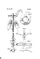
the same drawings 1-- Figure 1 is a central vertical section,
through the revolvingplatform of the device, the central working parts thereof being shown in elevation. I
Fig. 2 is a plan view of the'same. Fig. 3 is an enlarged fragmentary sec- .tional. view partially in elevation, of the centrally disposed vertical supporting tiltable shaft shown in Fig. l I
Fig. 4 is a view similar to Fig. 3 look; Fig. 5 isan enlarged detail viewiofthe Fig. 6- is a plan view of the same. Fig. 7 1s a plan view of one of the rocking cra'dle members. 1
8 is a bottom plan view of the supporting anti-friction table on which the revolving elements of the structure are 'de-' I signed to rotate. j I I I Fig. 9 is an enlargedsectional View on line 9 9.of Fig. 1. Fig. 10. is a section m1 line 10- l0 of .Referr irig; to the cirawirige, l fdesigna'tes generally a suitable supporting base com prising members 2 extending at right angles to one another and provided near the outer ends thereof with a plurality of suitable upwardly extending inclined supporting members 3 securely bolted as at 4 at their 7 upper ends to an annular supporting table member 5 having a centrally disposed circular aperture 6. The members 3 are further provided intermediate their length with one or more tie bolts 7 bolted or otherwise secured as at 8 to the members 3 and constituting WltlltllB latter, the bolt 5 and the base 1, a rigid unitary supporting structure.
Rotatably mounted on and anti-friction ally supported as by a ball race 9 is a shaft supporting member or casting 10. The member 10 is preferably machined and provided witha depending hub portion 11 arranged to revolveyvithin the guiding aperture 6 of the table 5 and is further provided with annular grooves 12 forming a suitable guide for the ball race 9. The table 10 is provided on its upper surface with similar'annular ball-retaining grooves 13, opposing the grooves 12. As best seen in Fig. 3 the member 10 is further provided on its upper surface with oppositely disposed grooves or recesses 14 forming a rocking seat for trunnions 15 on a shaft sup porting cradle member 16. The member 16 is provided with machined grooves or recesses 17 disposed at right angles to the trunnions 15 and these grooves 17 provide arocking support for trunnions 18 inte- .-grally formed with a shaft supporting sleeve member or casting 19. The member 19 is provided with a central longitudinally extending aperture 20 in which is rigidly secured for longitudinal adjustment as by the bolt 22, a substantially vertical rotatable uppersuoporting shaft 21.
The member 10 is provided with an outer annular shoulder or depression 23 forming a seat for a horizontally disposed gear 24 rigidly connected, preferably by shrinking, to the member 10. The table 5 is provided on its lower surface with a plurality of depend'ng flanged reinforcing web members 25 by means of which the table 5 is securely bolted to the frame members 3. The table 5 is further provided on the horizontal portion thereof with an aperture 26 through which passes a' vertically disposed drive shaft 27. The shaft 27 is provided at its upper end with a nut and washer 28 suitably spaced 'by means of a housing member 29 from the table 5' and. antifrictionally spaced from said housingby a thrust bearlng 30. 'Rigidly secured to the shaft 27 within the housing 29 is a pinion 31 meshing with the gear 24. The shaft 27 is further held in fixedrelation to the table 25 by a ournaled bearing support 32 forming an integral portion of one of the flange members 25 of the table member 5. The cradle supporting member 10 is suitably centrally apertured asat .33 to accommodate the reels ing movement of the shaft 21 and sleeve 10 on the oppositely disposed pairs of trunnions 18 and 15.
The upper portion of the member 19 integrally formed with an annular supporting plate 34 having a continuous upturned outer flange portion 35 in which are adapted to be secured a plurality of supporting eye and bolt members, 36. The latter provide means for attachment for a plurality of guides or supporting tie members or ropes 37 which are rigidly secured as at 38 to a rotating platform 39. The platform 39 is in the form of an annular ring being centrally apertured as at 40 to permit the supporting structure above described to extend therethrough. The annular portion 39 of the platform isdesigned toprovide seats for persons who are to be amused by the device.
The lower end of the shaft 27 is ournaled in a bearing 41 and is provided'at its lower end with a universal connection 42 with the upper end of an intermediate inclined shaft 43 having at its'lower end a similar universal connection 44 with the upper end of a stud shaft 45. The latter is rotatably sup ported at its upper end by the journal bracket46 attached to the member 3 and at its lower end is suitably journaled as at 47 in the base 1 of the machine (Fig. 1). A bevel pinion 48 is rigidly secured near the lower end of the shaft and meshes with a second pinion 49 rigidly mounted on one end of the horizontally disposed power shaft 50. The latter is rotatable and horizontally supported by bearings 51 and 52 secured in any desired manner within the base of the supporting structure. From the foregoing it will be seen that when the amusement device is in operation the shaft 21 is rotated by means of the cooperative driving relation of the power shaft 50, gears 48 and 49. shafts 43, 45 and 27, pinion 31 and gear 24.
As best seen in Figs. 1 and 4 a shaft 53 is rotatably mounted in a vertical position within the base 1 of the supporting frame structure, being journaled at its lower end in a suitable bearing 54 attached to said base and similarly journaled near its upper end within said frame structure. It will be observed that when the upper shaft 21 is in its normalvertical position the same is in al nement with the shaft 53, there being no positive driving engagement between the respective shafts. The upper end of the shaft 53 has rigidly secured thereto at its upper .end a dip bracket member 55 comprising a hub portion 55 and an upper curved guide portion 56 having an elongated slot 57 arranged centrally thereof. The lower end of the shaft 21 is apertured and threaded as in Fi 2 twelve sets of these u s or an porting members 37 extending radially to suitable connections on the platform 39. The latter is further provided with a plurality of upwardly extending reinforcing members Ti. and equal number of transversely crossing supports 72 inclined thereto and serving to reinforce the platform structureas an en tirety. The upper end of the shaft 21 has a rigid supporting plate 73 mounted thereon and having a continuous annular flange Tl similar to the flange on the plate 341:. Preferably an equal number of guy wires 37 extend radially from different eye and bolt connections T5 of the annular flange 74 to suitable ears 76 'orpoints of support on the upstanding members Ti.
As best seen in Figs. 1, 2, 9 and 10 the operation of my amusement device is con trolled from a single source of power. The latter may be a motor or gasoline engine and illustrated in the drawings 1 have shown an internal combustion engine of any desired form indicated at 77 and preferably located within the base of the supporting structure. Power from the plant 7'? is supplied by a belt/78 to a pulley 79 on one end of a shaft 80 mounted on the base of the structure. The other, end of the shaft 80 is provided with a pinion 81 meshing with and driving a gear 82 mounted intermediate the length of a second shaft 88 supported at either end by bearings 84 on the base of the device and having a plurality of pulleys 85 and 85. thereon. Power to the shaft 50 is supplied from the shaft 83 by a belt 86 passing over a drum clutch 87 on the inner end of the shaft 50. By operating the lever 69 the rotation of the shaft 50 may be controlled by actuation of the drum clutch 87 and the rotation of the shaft 50 and shaft 21 may be stopped independently of the shaft 53 and other rotating elements of the mecha nism. I have provided two operating speeds for the shaft 53 and consequently may vary the speed of the table dipping motion of the platform 39. To this end I have provided intermediate the shaft 67 a double cone clutch indicated at 88, and comprising idler portions 89 and 90 loosely revolving at different speeds on the shaft 67 by reason of the difference in size of the pulleys 85 and 85. The clutch 88 further comprising a central cone portion 91 keyed to the shaft 67. Referring to Fig. 9, when it is desired to rotate the shaft 67 and shaft 53 geared thereto at a comparative slow rate of speed I move the control lever 70 and slide rod 92 connected thereto tothe left. The cone portion 91 keyed to the shaft 67 is moved by the fingers 93 into frictional driving engagement with the previously loosely rotating member 89 of the clutch and this driving engagement is imparted to the shaft 67 and shaft 53, geared thereto. When it is desired to increase the speed after the device has been. in operation I move the control lever 70 to the right and I effect a similar driving operation of the keyed portion 91 of the clutch with the loosely rotating pulley member 90 and by reason of the increase in speed between the pulleys 89 and 90 I efiect an increased speed' of theshaft 67 and conse quently the shaft 53 and the speed of the dipping motion is proportionately increased. Any desired number of speed reductions may be employed by increasing the number of pulleys shown in Fig. 9 and any desired speed ratio may be obtained by varying the size of the several'pulleys described.
Suitable bra-king mechanism for the device have been provided on the shaft 45 and comprise a brake drum 94: mounted on said shaft and having a brake shoe 95 loosely bearing thereagainst and having a suitable connection to the lower end of a hand control lever 96. Referring to Fig. 9 when it is desired to brake the mechanism to bring the platform 39 to a stop the movement of the brake lever 96 to the right brings the brake shoe 95 into tight frictional engagement with the drum 94 resulting in cessation of rotation of the shaft 4L5 and connections thereabove. This braking operation is performed after the shaft 50 has been disen gaged from the power plant by a movement of the control lever 69.
What is claimed is: v 1. An amusement device comprising a frame. a pair of rotatable cradles supported by said frame, one of said cradles being movable in vertical planes relative to the other, an upper shaft journaled in said movable cradle, and movable in vertical planes at right angles to the planes of movement of said movable cradle, a lower shaft journaled insaid frame and having means engaging said upper shaft, whereby said upper shaft is carried around with said lower shaft, a rotatable platform carried by said upper shaft, and means for rotating said shafts.
2.-An amusement device comprising in combination: a frame, a rotary cradle held from vertical movement supported by said frame, a second rotary cradle supported by said frame and movable in vertical planes relative to said first mentioned cradle, an upper shaft journaled in said second cradle and movable in vertical planes relative thereto, a lower shaft journaled in said frame, a yoke carried by said lower shaft and engaging the lower end of said upper shaft to limit the oscillatory movement thereof, a rotatable platform carried by said upper shaft, and means for rotating said upper and lower shafts.
3. An amusement device comprising in combination: a supporting frame including a shaft, a rotatable platform carried by said frame, a table mounted in the upper end of said frame, a gear supporting member rotatably mounted on said table, a gear carried by said rotatable member, a cradle member mounted for oscillatory movement Within said rotatable member, a sleeve mounted for oscillatory movement in said cradle member, and adjustably carrying said shaft, and means for continuously rotating. said gear and said rotatable member on said table, whereby oscillatory movement of said shaft is permitted in planes at right angles to one another during the rotation of said rotatable member, said oscillatory movement of said shaft being transmitted to said platform during the rotation of the latter.
4. An amusement device comprising in combination: a supporting frame including a shaft, a rotatable platform carried by said frame, a table secured to the upper portion of said frame, a rotatable member carried by said table, anti-friction means interposed between said rotatable member and said table, diametrically opposed recesses dis-v posed in said rotatable member, a cradle member mounted for oscillationin said rosaid lower shaft and carrying said plat-' form, guiding means connecting said shafts whereby said upper shaft and said platform are carried around with said lower shaft, means for rotating said upper shaft 1nde-' pendently of said lower shaft, means for rotating said lower shaft independently of said upper shaft, said upper and lowershaft rotating means being separately controlled and operated from a common source, and means for braking said shafts.
6. An amusement device comprising in:
combination: a platform'continuous around a center, anupwardly extending lower shaft arranged Within said platform, an upper shaft pivot-ally supported at a point above said lower shaft and carrying said plat form, guiding means connecting said shafts whereby said upper shaft and said platform are carried around with. said lower shaft, means for rotating said upper shaft independently of said lower shaft, means for rotating said lower shaft at variable speeds, said upper and lower shaft rotating means being separately controlled and operated from a common source, and means for braking said shafts. In testimony whereof I affix my'signature. THOMAS L. STINE;
Priority Applications (1)
| Application Number | Priority Date | Filing Date | Title |
|---|---|---|---|
| US599532A US1521568A (en) | 1922-11-07 | 1922-11-07 | Amusement device |
Applications Claiming Priority (1)
| Application Number | Priority Date | Filing Date | Title |
|---|---|---|---|
| US599532A US1521568A (en) | 1922-11-07 | 1922-11-07 | Amusement device |
Publications (1)
| Publication Number | Publication Date |
|---|---|
| US1521568A true US1521568A (en) | 1924-12-30 |
Family
ID=24400001
Family Applications (1)
| Application Number | Title | Priority Date | Filing Date |
|---|---|---|---|
| US599532A Expired - Lifetime US1521568A (en) | 1922-11-07 | 1922-11-07 | Amusement device |
Country Status (1)
| Country | Link |
|---|---|
| US (1) | US1521568A (en) |
-
1922
- 1922-11-07 US US599532A patent/US1521568A/en not_active Expired - Lifetime
Similar Documents
| Publication | Publication Date | Title |
|---|---|---|
| US2229966A (en) | Amusement machine | |
| US815211A (en) | Amusement-vehicle. | |
| US2294166A (en) | Amusement device | |
| US2765168A (en) | Carousel | |
| US1521568A (en) | Amusement device | |
| US2274956A (en) | Operating mechanism for amusement devices | |
| US1402368A (en) | Amusement apparatus | |
| US2667227A (en) | Variable speed counter-rotating rotor system for helicopters and control means therefor | |
| US946639A (en) | Rotary swing. | |
| US1529512A (en) | Carrousel | |
| US938283A (en) | Carousel. | |
| US1996923A (en) | Merry-go-round | |
| US2895734A (en) | Combination see-saw and merry-go-round | |
| US3187461A (en) | Wheel actuated roundabout toy | |
| US1037453A (en) | Roundabout. | |
| US1382181A (en) | Gyrating-machine | |
| US3506260A (en) | Plural axes carnival ride | |
| US2035168A (en) | Intermittent grip device | |
| US871744A (en) | Amusement apparatus. | |
| US841424A (en) | Merry-go-round. | |
| US1433285A (en) | Rotary swing | |
| US1523871A (en) | Amusement apparatus | |
| US660168A (en) | Merry-go-round. | |
| US1248327A (en) | Cheese-stirring machine. | |
| US2389456A (en) | Merry-go-round on water |