US151663A - Improvement in brick-machines - Google Patents
Improvement in brick-machines Download PDFInfo
- Publication number
- US151663A US151663A US151663DA US151663A US 151663 A US151663 A US 151663A US 151663D A US151663D A US 151663DA US 151663 A US151663 A US 151663A
- Authority
- US
- United States
- Prior art keywords
- brick
- molds
- head
- cross
- followers
- Prior art date
- Legal status (The legal status is an assumption and is not a legal conclusion. Google has not performed a legal analysis and makes no representation as to the accuracy of the status listed.)
- Expired - Lifetime
Links
- 230000006872 improvement Effects 0.000 title description 3
- 239000011449 brick Substances 0.000 description 15
- 239000004927 clay Substances 0.000 description 9
- 239000007787 solid Substances 0.000 description 3
- 239000005441 aurora Substances 0.000 description 2
- 230000007246 mechanism Effects 0.000 description 2
- 239000002184 metal Substances 0.000 description 2
- 229910052751 metal Inorganic materials 0.000 description 2
- 230000001105 regulatory effect Effects 0.000 description 2
- 229910000760 Hardened steel Inorganic materials 0.000 description 1
- 230000009471 action Effects 0.000 description 1
- 238000010276 construction Methods 0.000 description 1
- 230000003467 diminishing effect Effects 0.000 description 1
- 230000014759 maintenance of location Effects 0.000 description 1
- 229930187329 perforatin Natural products 0.000 description 1
- BJMYIAUNRHAYSL-UHFFFAOYSA-N perforatine Natural products CC1(C)OC2(O)C(=O)C13OC(=O)C=CC3(C)C4CCC5(C)C(OC(=O)C6OC56C24C)c7cocc7 BJMYIAUNRHAYSL-UHFFFAOYSA-N 0.000 description 1
- 230000007480 spreading Effects 0.000 description 1
Images
Classifications
-
- B—PERFORMING OPERATIONS; TRANSPORTING
- B30—PRESSES
- B30B—PRESSES IN GENERAL
- B30B11/00—Presses specially adapted for forming shaped articles from material in particulate or plastic state, e.g. briquetting presses, tabletting presses
- B30B11/02—Presses specially adapted for forming shaped articles from material in particulate or plastic state, e.g. briquetting presses, tabletting presses using a ram exerting pressure on the material in a moulding space
- B30B11/04—Presses specially adapted for forming shaped articles from material in particulate or plastic state, e.g. briquetting presses, tabletting presses using a ram exerting pressure on the material in a moulding space co-operating with a fixed mould
Definitions
- Patented Japanese Patented )une 2,1874.
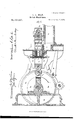
- FIG. 1 is a perspective view of my improved machine as arranged for use.
- Fig. 2 is an elevation of one end of the same, a portion of the frame being broken away to show the arrangement of the operative mechanism.
- Fig. 3 is a vertical central section upon line of Fig. 2.
- Fig. 4 is a like view upon line z z of Fig. 3; and
- Fig. 5 is a perspective view of a brick produced by my machine.
- the design of my invention is to improve the operation and increase the durability of mechanism for producing brick, and also to render such product stron ger and more durable; and it consists, principally, in the means employed for giving to the followers a positive verticalmotion without side pressure, substantially as and for the purpose hereinafter shown. It consists, further, in the means employed for regulating the quant-ity of clay delivered to the molds, substantially as and for the purpose hereinafter set forth. It consists, further, in the means employed for imparting the required pressure to the clay within the molds, substantially as is hereinafter shown and described. It consists, further, in the means employed for adjusting the vertical position of the followers, and thereby regulating the thickness of the brick, substantially as is hereinafter specified.
- a and A representtwo standards, which are secured to and extend upward from a suitable base-plate, B, with their faces arranged upon parallel lines.
- a horizontal plate, C which extends between and is secured to said standards, and furnishes a support for a series of molds, D, that have the usual form, internally, except that they have no bottoms.
- a vertical slot, A' within which is fitted a slide, E, that has free vertical movement, and contains one end of a journal, j', that is formed upon the end of a cross-head, F, said journal being rigidly secured within said slide, so as to prevent said cross-head and slide from changing their relative positions.
- a second shaft, L is journaled within bearings a and a at one side of the standards A and A, and is provided with pinions l and l, which mesh with the gear-wheels II and' Il, by which means a rotary movement of said shaft L will be communicated through said pinions l and l, gear-wheels II and H, shaft I, and connections Gr and G, to the crosshcad F, and cause the latter to reciprocate vertically within the slots or ways a and a.
- a slotted guide, M which extends downward nearly to the gear-wheel H, and contains the correspondingly-shaped bearing end n of a second cross-head, N, which latter has a vertical motion, and is provided upon its upper side with followers N and N that lit within the lower ends of the molds D and D.
- the lower followers i and N perform several offices, viz: They close the lower ends of the A'rEN'r OFFICE.
- Vmetal bar or plate, Q is journaled at one end vupon each ⁇ iournal f of the cross-head F, and
- a lug, a' that has a wedgesliaped form from above downward, and at its lower broad end is horizontal, so that when the cross-head F moves downward the lowerv divided end of the bar Q will be spread apart until the shoulders q and q have passed below said lug, when said bar will close together so as to cause said shoulders to engage with said lug. If, now, the cross-head F is moved upward, the bars Q, and Q, operating through the lugs a', will raise the cross-headN directly upward, the motion thus imparted being in a vertical line and free from any side pressure.
- two bearing-plates, N and N formed of hardened steel, are bolted securely upon the lower side of said cross-head N, and receive the impact and ,pressure of the upper end of the bar O.
- Clay for the molds is placed within a hopper, U, that is attached to suitable supports above and in rear of the same,which clay from said hopper passes downward into a series of boxes, o and e, that are formed within a sweep, V, which slides within suitable guides YV and NV, between said hopper and molds.
- the feed-boxes t and e correspond to the like features of the molds D and D, while vertically said boxes have such depth as to enable each to contain charge sufficient to forni the largest size of brick.
- Motion is imparted to the sweep by means of two bell-craii ks, X and X, which are secured to or upon a shaft, X', that is jouriialed upon the rear side of the standards A and A, the lon arin of each crank being contained' within a slot formed in the lower side of said sweep, while its short end extends forward and downward, and is provided with a frictioii-roller,
- an angle-plate, e' is fitted within the forward end of each box lv, with its 'long vertical arm filling said end, while its short horizontal arm projects forward within a corresponding groove formed in the edge of said box.
- a screw, t passing horizontally inward through the forward end of each box t, has its inner threaded end contained within a corresponding opening provided in the plate c', and furnishes a means whereby the latter may be conned in place.
- each mold D a metal bar, D', and within the same secure in a vertical position a number of round studs or pins, d and d, which extend upward to the upper side of said mold, and at their upper ends are pointed, as shown.
- the followers F' and N are provided with openings which correspond in number, size, and position to the pins d and d, so as to enable them to move freely within the molds, said lower follower N' being entirely above the plate D', and operated by means of standards n' and n', that pass upward between the edges of said plate and the sides of the mold.
- the plates D' and D' are secured in place by means of screws d' and d', so as to enable the same and the pins d and d to be removed when desired.
- the operation of the pins is to force the clay outward, and increase its density, and to prevent the retention of air within the brick, both of which results are obtained at an additional cost that is considerably less than the saving effected in the quantity of clay.
- the brick is capable of forming a firmer bond when placed within a wall than can be formed by solid brick.
- the means employed for operating the combined sweep and feeding-box consisting oi the bell-cranks vX and X, friction-rollers Y and Y, and gear-wheels H and H, provided with the cam-grooves h' and h', constructed and combined in the manner and for the purpose set forth.
Landscapes
- Engineering & Computer Science (AREA)
- Mechanical Engineering (AREA)
- Press-Shaping Or Shaping Using Conveyers (AREA)
Description
4 Sheets--Sheet1. I. L`. HILT.
BrickMachines.
Patented June 2.1874.
W'LTNES 5Is= -f/a/J.
4 Sheets--Sheet 2.
Brick-Machines.
LQ'HILT.
Patented )une 2,1874.
4 Sheet's--Shet 3. l. L. HILT.
Brick-Machines. No.1`51,663. Patentedlune 2,1874.
4 Sheets--Sheet 4.
I. L. HILT. BrickjMachines.
UNITED' STATES.
IsAAc L. nur, or AURORA, ILL'rNois.
IMPROVEMENT IN BRICK-MACHINES.
Specification forming part of Letters Patent No. 151,663, dated June 2, 1874; application filed March 18, 1874.
To all whom it may concern:
Be it known that I, ISAAC L. HILT, of Aurora, in the county of Kane and in the State of Illinois, have invented certain new and useful Improvements in Brick-l iachines; and do hereby declare that the following is a full, clear, and exact description thereof, reference heilig had to the accompanying drawings making a part of this specification, in which- Figure l is a perspective view of my improved machine as arranged for use. Fig. 2 is an elevation of one end of the same, a portion of the frame being broken away to show the arrangement of the operative mechanism. Fig. 3 is a vertical central section upon line of Fig. 2. Fig. 4 is a like view upon line z z of Fig. 3; and Fig. 5 is a perspective view of a brick produced by my machine.
Letters of like name and kind refer to like parts in each of the figures.
The design of my invention is to improve the operation and increase the durability of mechanism for producing brick, and also to render such product stron ger and more durable; and it consists, principally, in the means employed for giving to the followers a positive verticalmotion without side pressure, substantially as and for the purpose hereinafter shown. It consists, further, in the means employed for regulating the quant-ity of clay delivered to the molds, substantially as and for the purpose hereinafter set forth. It consists, further, in the means employed for imparting the required pressure to the clay within the molds, substantially as is hereinafter shown and described. It consists, further, in the means employed for adjusting the vertical position of the followers, and thereby regulating the thickness of the brick, substantially as is hereinafter specified. It consists, further, in the peculiar construction of the followers and perforatin gcores, and their combination with each other and the molds, substantially as and for the purpose hereinafter shown. It consists, finally, in the means employed for operating the combined feeding-box and sweep, substantially as and for the purpose hereinafter set forth.
In the annexed drawings, A and A representtwo standards, which are secured to and extend upward from a suitable base-plate, B, with their faces arranged upon parallel lines.
.At a point midway between the upper and lower ends of the standards A and A is placed a horizontal plate, C, which extends between and is secured to said standards, and furnishes a support for a series of molds, D, that have the usual form, internally, except that they have no bottoms. From a point at or near the lower side of the molds D, upward to or near the upper end of each standard, is formed a vertical slot, A', within which is fitted a slide, E, that has free vertical movement, and contains one end of a journal, j', that is formed upon the end of a cross-head, F, said journal being rigidly secured within said slide, so as to prevent said cross-head and slide from changing their relative positions. Upon the lower side of said cross-head F are secured.
or formed a number of followers, F and F', which correspond in size, shape, and horizontal position to the molds D and D, and lill the latterv when said cross-head is moved downward. Motion is imparted to the cross-head F by means of two connecting-bars, G and G, one of which is pivoted at one end to or upon one of the journals f, and, at its opposite end, isjournaled upon a crank-pin, h, that is -secured within and extends outward from the face of a gear-wheel, H, said gear-wheel being attached to or upon one end of a shaft, I, that is suitably journaled within a bearing, K, which is attached to or upon the upper side of the base-plate B. A second shaft, L, is journaled within bearings a and a at one side of the standards A and A, and is provided with pinions l and l, which mesh with the gear-wheels II and' Il, by which means a rotary movement of said shaft L will be communicated through said pinions l and l, gear-wheels II and H, shaft I, and connections Gr and G, to the crosshcad F, and cause the latter to reciprocate vertically within the slots or ways a and a. Attached to the lower side and at each end of the plate C is a slotted guide, M, which extends downward nearly to the gear-wheel H, and contains the correspondingly-shaped bearing end n of a second cross-head, N, which latter has a vertical motion, and is provided upon its upper side with followers N and N that lit within the lower ends of the molds D and D. The lower followers i and N perform several offices, viz: They close the lower ends of the A'rEN'r OFFICE. v
tains an eccentric, P, which eccentric is secured upon and revolves with the shaft I. The position of the eccentric l) with relation to the shaft I is such as to cause it to raise the bar O and cross-head N for a short distance at the instant that the upper cross-head F has reached the limit of its downward motion, by which means the final pressure is given to the contents of the molds D and D. After the clay is pressed its lateral expansion within the molds causes it to adhere so firmly to the saine as to render necessary, in order to loosen and raise the brick, the use of far more force than has heretofore beenapplied to the lower crosshead 5 and, as the application of such excessivepower by the direct action of cams or other like means would have a tendency to force said cross-head and its followers so firmly against one side of the slotted guides M and M and of the molds D and D, it is found necessary to apply the raising-power from above and in a vertical line. To accomplish such result, a
Vmetal bar or plate, Q, is journaled at one end vupon each `iournal f of the cross-head F, and
extending downward alon the end of the molds D and D, and the outer side of the guide M is slottedfroin near its lower end upward to or near its journalcd end. At its lower end the bar Q is divided and the ends of the sections rouiided, while, as the lower end of the slot qis square, there is formed within each section a right-aiigled shoulder, q', as seen in Fig. 2. Upon the end of the bearing a ofthe cross-head F is fixed a lug, a', that has a wedgesliaped form from above downward, and at its lower broad end is horizontal, so that when the cross-head F moves downward the lowerv divided end of the bar Q will be spread apart until the shoulders q and q have passed below said lug, when said bar will close together so as to cause said shoulders to engage with said lug. If, now, the cross-head F is moved upward, the bars Q, and Q, operating through the lugs a', will raise the cross-headN directly upward, the motion thus imparted being in a vertical line and free from any side pressure. lVhen the followers N and Nl have been raised until their upper surfaces are nearly flush with the upper side ofthe molds D and D, two camsliaped projections, q and q, formed upon the sides and near the longitudinal center of the slot q, engage with a lozenge-shaped lug, R, that is affixed to the end of said molds, and, by spreading the bar Q, release its shoulders q from engagement with the lug a', after which the remaining upward movement of said followers is effected by means of two camplates, S and S, that are affixed to the inner faces of the gear-wheels H and H, and engage with two friction-rollers, T and T, that are pivoted upon the lower side of the cross-head N, said cam-plates holding said eross-headin such elevated position for the necessary length of time, and then permitting it to drop to its lower position. In order that the accuracy of the movements of the lower cross-head N may be insured, and opportunityafforded for chan ing its vertical position-with relation to the upper cross-head F, so as to vary the thickness of the brick, two bearing-plates, N and N, formed of hardened steel, are bolted securely upon the lower side of said cross-head N, and receive the impact and ,pressure of the upper end of the bar O. By iiiereasin or diminishing the thickness of said bearing-plates N and N, the height to which said cross-head and its followers will be raised may be varied at will. Clay for the molds is placed within a hopper, U, that is attached to suitable supports above and in rear of the same,which clay from said hopper passes downward into a series of boxes, o and e, that are formed within a sweep, V, which slides within suitable guides YV and NV, between said hopper and molds. In position and horizontal dimensions the feed-boxes t and e correspond to the like features of the molds D and D, while vertically said boxes have such depth as to enable each to contain charge sufficient to forni the largest size of brick.
Motion is imparted to the sweep by means of two bell-craii ks, X and X, which are secured to or upon a shaft, X', that is jouriialed upon the rear side of the standards A and A, the lon arin of each crank being contained' within a slot formed in the lower side of said sweep, while its short end extends forward and downward, and is provided with a frictioii-roller,
Y, that fits into a cam-groove, h, formed in the outer face of each gear-wlicel H, the shape of said cam-grooves being such as to cause said sweep to move forward as soon as the lower followers N and N have reached the upper end of the molds D and D, and return to its rear position when the charges of clay have fallen into said molds. After one series of brick has been made, and the saine have been aised to the upper side of the molds, the sweep V, upon its forward movement, pushes said bricks from said mold forward upon a table, Z, from whence they are conveyed to the kiln. In order that the size of each charge of clay may be adapt-ed to the thickness of the brick to be made an angle-plate, e', is fitted within the forward end of each box lv, with its 'long vertical arm filling said end, while its short horizontal arm projects forward within a corresponding groove formed in the edge of said box. A screw, t, passing horizontally inward through the forward end of each box t, has its inner threaded end contained within a corresponding opening provided in the plate c', and furnishes a means whereby the latter may be conned in place. By loosening the screw e", and inserting thin plates of metal between the plate e' and the end of the box e, any desired diminution of the length of the latter may be effected.
In the making of an ordinary solid brick many difficulties arise, among which are the presence of air in its interior, by means of which a fracture is occasioned the long time required for burning, and, in consequence, its excessive cost; and lastly, its great weight in proportion to its strength.
lo remedy these objections I attach to the bottom of each mold D a metal bar, D', and within the same secure in a vertical position a number of round studs or pins, d and d, which extend upward to the upper side of said mold, and at their upper ends are pointed, as shown.
The followers F' and N are provided with openings which correspond in number, size, and position to the pins d and d, so as to enable them to move freely within the molds, said lower follower N' being entirely above the plate D', and operated by means of standards n' and n', that pass upward between the edges of said plate and the sides of the mold.
The plates D' and D' are secured in place by means of screws d' and d', so as to enable the same and the pins d and d to be removed when desired.
As thus constructed the operation of the pins is to force the clay outward, and increase its density, and to prevent the retention of air within the brick, both of which results are obtained at an additional cost that is considerably less than the saving effected in the quantity of clay.
When in the kiln so large a proportion of the brick is brought into direct contact with the heat as to render the burning a matter which requires but a small proportion of the time usually necessary; the brick is more thoroughly burned; and, from the increased extent of its exterior or glazed surface, possesses greater strength than would be possible if it were made solid.
In addition to the above-named advantages the brick is capable of forming a firmer bond when placed within a wall than can be formed by solid brick.
Having thus fully set forth the nature and merits of my invention, what I claim as new 1sl. In combination with the vertically-moving cross-head N and followers N' and N', the bars Q and Q, provided with the slats q and q, shoulders q' and q', and projections q" and q", pivoted upon the journals f andf, engaging with the lugs u' fn' and R, substantially as and for the purpose shown.
2. In combination with the feed-boxes e and fv the angle-plate c', made adjustable longitudinally and horizontally Within the said feedboxes, in the manner and for the purpose substantially as set forth. n
3. In combination with the cross-head N,
and with theV followers N' and N', working vertically within the molds D and D, the bar O, eccentric I), and shaft I, substantially as and for the purpose shown and described.
4. In combination with the cross-head N and pressure-bar O, the bearing-plates N" and N", secured to or upon said cross-head, substantially as and for the purpose specified.
5. rIhe perforated followers I1" and N', molds D and D, plates D' and D', and pins or cores d and d, said parts being` constructed and combined in the manner and for the purpose substantially as shown.
6. The means employed for operating the combined sweep and feeding-box, consisting oi the bell-cranks vX and X, friction-rollers Y and Y, and gear-wheels H and H, provided with the cam-grooves h' and h', constructed and combined in the manner and for the purpose set forth.
In testimony that I claim the foregoing I have hereunto set my hand this 19th day of January, 1874.
ISAAC L. HILT.
Witnesses:
GEO. S. PRINDLE, WILLIAM FITCH.
Publications (1)
| Publication Number | Publication Date |
|---|---|
| US151663A true US151663A (en) | 1874-06-02 |
Family
ID=2221075
Family Applications (1)
| Application Number | Title | Priority Date | Filing Date |
|---|---|---|---|
| US151663D Expired - Lifetime US151663A (en) | Improvement in brick-machines |
Country Status (1)
| Country | Link |
|---|---|
| US (1) | US151663A (en) |
-
0
- US US151663D patent/US151663A/en not_active Expired - Lifetime
Similar Documents
| Publication | Publication Date | Title |
|---|---|---|
| US151663A (en) | Improvement in brick-machines | |
| US694A (en) | Machine fob molding and pressing bricks | |
| US74207A (en) | Improved brick-machine | |
| US229247A (en) | Brick-machine | |
| US150924A (en) | williams | |
| US70585A (en) | Stephen w | |
| US272224A (en) | pitzpatriok | |
| US553885A (en) | Brick-machine | |
| US54610A (en) | Improved brick-machine | |
| US55432A (en) | Improvement in brick-machines | |
| US82116A (en) | Daniel hess | |
| US61108A (en) | William a | |
| US809250A (en) | Cement-brick machine. | |
| US254525A (en) | woodwaed | |
| US52674A (en) | Improved brick-machine | |
| US361464A (en) | Eeginald stanley | |
| US289882A (en) | bennor | |
| US555349A (en) | wallace | |
| US141855A (en) | Improvement in brick-machines | |
| US150292A (en) | Improvement in brick-presses | |
| US830111A (en) | Machine for making and re-pressing bricks. | |
| US8780A (en) | speissegger | |
| US791262A (en) | Brick-machine. | |
| US234101A (en) | Brick-machine | |
| US2619A (en) | Brick-press |