US1515791A - Printing press - Google Patents
Printing press Download PDFInfo
- Publication number
- US1515791A US1515791A US666598A US66659823A US1515791A US 1515791 A US1515791 A US 1515791A US 666598 A US666598 A US 666598A US 66659823 A US66659823 A US 66659823A US 1515791 A US1515791 A US 1515791A
- Authority
- US
- United States
- Prior art keywords
- roll
- impression
- cylinder
- type
- cam
- Prior art date
- Legal status (The legal status is an assumption and is not a legal conclusion. Google has not performed a legal analysis and makes no representation as to the accuracy of the status listed.)
- Expired - Lifetime
Links
- 230000007246 mechanism Effects 0.000 description 15
- 230000008878 coupling Effects 0.000 description 2
- 238000010168 coupling process Methods 0.000 description 2
- 238000005859 coupling reaction Methods 0.000 description 2
- 230000000994 depressogenic effect Effects 0.000 description 2
- XLYOFNOQVPJJNP-UHFFFAOYSA-N water Substances O XLYOFNOQVPJJNP-UHFFFAOYSA-N 0.000 description 2
- 101150109517 Camlg gene Proteins 0.000 description 1
- BFPSDSIWYFKGBC-UHFFFAOYSA-N chlorotrianisene Chemical compound C1=CC(OC)=CC=C1C(Cl)=C(C=1C=CC(OC)=CC=1)C1=CC=C(OC)C=C1 BFPSDSIWYFKGBC-UHFFFAOYSA-N 0.000 description 1
- ZPUCINDJVBIVPJ-LJISPDSOSA-N cocaine Chemical compound O([C@H]1C[C@@H]2CC[C@@H](N2C)[C@H]1C(=O)OC)C(=O)C1=CC=CC=C1 ZPUCINDJVBIVPJ-LJISPDSOSA-N 0.000 description 1
- 239000012634 fragment Substances 0.000 description 1
- 230000002093 peripheral effect Effects 0.000 description 1
Images

Classifications
-
- B—PERFORMING OPERATIONS; TRANSPORTING
- B41—PRINTING; LINING MACHINES; TYPEWRITERS; STAMPS
- B41F—PRINTING MACHINES OR PRESSES
- B41F15/00—Screen printers
- B41F15/08—Machines
- B41F15/12—Machines with auxiliary equipment, e.g. for drying printed articles
-
- B—PERFORMING OPERATIONS; TRANSPORTING
- B41—PRINTING; LINING MACHINES; TYPEWRITERS; STAMPS
- B41L—APPARATUS OR DEVICES FOR MANIFOLDING, DUPLICATING OR PRINTING FOR OFFICE OR OTHER COMMERCIAL PURPOSES; ADDRESSING MACHINES OR LIKE SERIES-PRINTING MACHINES
- B41L21/00—Devices for conveying sheets or webs of copy material through the apparatus or machines for manifolding, duplicating, or printing
- B41L21/02—Devices for conveying sheets or webs of copy material through the apparatus or machines for manifolding, duplicating, or printing for conveying sheets
- B41L21/06—Grippers
Definitions
- My present invention relates to printing and more particularly to printing presses and it has for its object to provide a machine of this character and of the rotary type that will combine the facilities of a rotary press and a reciprocating bed press and be capable of ordinary printing, color work, duplicating and such operations as are not ordinarily performed on a single press.
- My improvements are directed in part toward arrangements whereby auxiliary mechanisms are all controlled from the type roll and toward the mechanism for gripping and stripping the paper.
- the invention resides in certain improvements and combinations of parts all as will be hereinafter more fully described, the novel features being pointed out in the claims at the end of the specification.
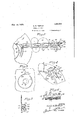
- Figure 1 is a side view of a rotary printing press constructed in accordance with and illustrating one embodiment of my invention, portions of the inking and feeding mechanisms being broken away.
- Figure2 is a. side view of a fragment of the type roll and the inking mechanism.
- Fii' ure 3 is an elevation of the gripper cam for t e impression roll viewed from the inside of the frame.
- Figure 4C is an enlarged fragmentary elevation of the gripper mechanism.
- Figure 5 is an enlarged detail section on the line 5-5 of Figure 1.
- Figure 6 is a fragmentary plan view of the gripper.
- Figure 7 is a fragmentary view partly in section of the coupling between the type cylinder and the impression cylinder and Figure 8 is an enlarged perspective view of an element of said gearing.
- A indicates the type cylinder and B the impression roll which are geared together as indicated by the dotted lines 1 and 2 to work in unison.
- the type cylinder is mounted on a. shaft 3 and the impression roll turns on a shaft 4 carried by eccentric supports 5 so that the impression roll may be carried toward and from the type roll into and out of printing contact through the operation of devices hereinafter described.
- rIhe raised contact surface G of the type cylinder equals half of its circumference and t-he type cylinder makes two revolutions of the impression roll while making one revolution of its own. In this way, the impression roll makes one revolution in Contact with the type roll while the impression is being made. During the next revolution of the impression roll the roll is out of Contact with the type cylinder.
- the sheets C to be printed upon are fed from a table 7 under the control of a detentor arresting ⁇ device in the present form of a linger 8 pivoted at 9 and normally held by a spring 10 in a notch 11 of the table 7 to prevent the sheet from moving into the printing ⁇ couple at other than the proper moment.
- a roller 12 on the nger cooperates with a cam 13 on the end of the type cylinder A which cam, at the proper time, depresses the linger and releases the sheet.
- the latter is gripped by a gripper 14 located in a cavity 15 in the impression roll B. It is adapted to grip the sheet as shown in Figure 1 along an edge of the cavity throughY the influence of a. spring 1G connected to it below its pivot 17.
- a link 19 terminating in a roller 20 that cooperates with a cam ring 21 suitablv fixed stationarily to the frame of the machine.
- the point 22 of the cam 21 is pivoted at 23 to be raised and lowered by a link 24 terminating at its upper end in a roller 25 adapted to be engaged by a cam 26 also on the end of the type cylinder A.
- a spring 27 tends to hold the cam point 22 raised as in Figure 3.
- the jaw 14.- is held open by its link roller 20 travelling on the inside of the fixed cam ring 21.
- the roller 20 reaches the end 28 and the spring 16 is no longer restrained, the gripper 14 engages the edge of a sheet which has just previously been released b y the linger S.
- the ca-m 26 immediately de'presses the movable cam point 22 and the roller 2O rides outside of the cam ring 21 during a revolution of the impression roll B during which the impression is made through contact with the .type carrying portion oiE the the type roll A.
- a stripper 29 that is normally held raised by a spring 30 and is depressed at the proper time by a link 31 having a roller 82 at its upper end engaged by a cam l33 on the type roll A.
- the stripper passes the sheet on to a conveyor 34 on the roll shaft of which the stripper is pivoted.
- This shatt also carries a gear 36 meshing with a. gear 37 by which it is driven trom the gear 2 on the impression roll B.
- a detector lever 38 pivoted at 39 in the cavity 15 has fingers 40 against which the sheet is gripped by the gripper 14 but which are interspersed with the fingers 41 of the gripper as shown in Figure 6. Consequently, if no sheet is interposed the detector tinger 40 occupies the raised position 'of Figure 4 being held against a stop 41? by a spring 42. This carries a toot 43 on the detector into a position in which it will engage with a bell crank detent 44 having a fixed pivot 45 on the frame.
- the inking mechanisms shown in Figures 1 and 2 includes in the present instan-ce a reservoir 56 provided with an ink roll 5T having a ratchet 58 actuated by a pawl 5f) connected by links 60 with a liiik ($1 terminating in a roller (i2 thatisengagedbya cam G3 on the end ot the type cylinder .f ⁇ .
- a doctor roll (S4 is oscillated between this ink roll 5T and intermediate rolls (S5 and 6V which have a reversing endwise movement on opposite sides ot a Vxed roll e? to mix the ink.
- rl ⁇ h ⁇ e doctor roll is carried ou a pivoted arm GS and moved in one direction by a spring G9 and in the other direction by a link TO terminating in a roller 7l actuated by a cam 72 on the end ot the type cylinder A.
- a water feeding roll T9 running in a water tray 8O feeds to a distributing roll S1 through a doctor roll S2 pivoted at S3 and vibrated by means of a spring S4 and a link 85 havinga roller S6 engaged by a caml ST on the type roll A.
- the con'ibination with rotary type and in'lpression cylinders and paper teeding and stripping mechanism and inking mechanism therefor ⁇ oit a plurality of cams on the end Atace ot one ot said cylinders for actuating ⁇ said mechanisms.
Landscapes
- Engineering & Computer Science (AREA)
- Mechanical Engineering (AREA)
- Supply, Installation And Extraction Of Printed Sheets Or Plates (AREA)
Description
C. R. REDNER PRINTING PRESS Filed Oct. 4. 1923 INVENToR. Qciedne Patented Nov. 18, 1924.
GECIL R. REDNER, OF ROCHESTER, NEW' YORK.
PRINTING PRESS.
Application filed October 4, 1923. Serial No. 666,598.
i. To all whom t may concern.
.y this specification, and/to the reference numerals marked thereon..
My present invention relates to printing and more particularly to printing presses and it has for its object to provide a machine of this character and of the rotary type that will combine the facilities of a rotary press and a reciprocating bed press and be capable of ordinary printing, color work, duplicating and such operations as are not ordinarily performed on a single press. My improvements are directed in part toward arrangements whereby auxiliary mechanisms are all controlled from the type roll and toward the mechanism for gripping and stripping the paper. To these and other ends the invention resides in certain improvements and combinations of parts all as will be hereinafter more fully described, the novel features being pointed out in the claims at the end of the specification.
In the drawings:
Figure 1 is a side view of a rotary printing press constructed in accordance with and illustrating one embodiment of my invention, portions of the inking and feeding mechanisms being broken away.
Figure2 is a. side view of a fragment of the type roll and the inking mechanism.
Fii' ure 3 is an elevation of the gripper cam for t e impression roll viewed from the inside of the frame.
Figure 4C is an enlarged fragmentary elevation of the gripper mechanism.
Figure 5 is an enlarged detail section on the line 5-5 of Figure 1.
Figure 6 is a fragmentary plan view of the gripper.
Figure 7 is a fragmentary view partly in section of the coupling between the type cylinder and the impression cylinder and Figure 8 is an enlarged perspective view of an element of said gearing.
Similar reference numerals throughout the several views indicate the same parts.
Referring more particularly to the drawings A indicates the type cylinder and B the impression roll which are geared together as indicated by the dotted lines 1 and 2 to work in unison. The type cylinder is mounted on a. shaft 3 and the impression roll turns on a shaft 4 carried by eccentric supports 5 so that the impression roll may be carried toward and from the type roll into and out of printing contact through the operation of devices hereinafter described. rIhe raised contact surface G of the type cylinder equals half of its circumference and t-he type cylinder makes two revolutions of the impression roll while making one revolution of its own. In this way, the impression roll makes one revolution in Contact with the type roll while the impression is being made. During the next revolution of the impression roll the roll is out of Contact with the type cylinder.
The sheets C to be printed upon are fed from a table 7 under the control of a detentor arresting` device in the present form of a linger 8 pivoted at 9 and normally held by a spring 10 in a notch 11 of the table 7 to prevent the sheet from moving into the printing` couple at other than the proper moment. A roller 12 on the nger cooperates with a cam 13 on the end of the type cylinder A which cam, at the proper time, depresses the linger and releases the sheet. At this point the latter is gripped by a gripper 14 located in a cavity 15 in the impression roll B. It is adapted to grip the sheet as shown in Figure 1 along an edge of the cavity throughY the influence of a. spring 1G connected to it below its pivot 17. Above its pivot or turning center there is pivoted to it at 18 a link 19 terminating in a roller 20 that cooperates with a cam ring 21 suitablv fixed stationarily to the frame of the machine. The point 22 of the cam 21 is pivoted at 23 to be raised and lowered by a link 24 terminating at its upper end in a roller 25 adapted to be engaged by a cam 26 also on the end of the type cylinder A. A spring 27 tends to hold the cam point 22 raised as in Figure 3.
Assuming the parts of the gripper mechanism to be in the positions of Figure Ll, the jaw 14.- is held open by its link roller 20 travelling on the inside of the fixed cam ring 21. During this revolution of the impression roll it is passing the blank portion of the type roll A. IlVhen the roller 20 reaches the end 28 and the spring 16 is no longer restrained, the gripper 14 engages the edge of a sheet which has just previously been released b y the linger S. The ca-m 26 immediately de'presses the movable cam point 22 and the roller 2O rides outside of the cam ring 21 during a revolution of the impression roll B during which the impression is made through contact with the .type carrying portion oiE the the type roll A. Upon the completion oit that revolution the roller 2O on the gripper again rims otl:l of the fixed end 28 of the cam 21 and the gripper opens releasing the sheet C as at this time the link 24 is not depressed because the cam 2G is on the opposite side of its circular path. Consequently, the gripper' roller 2O passes beneath the movable point 22 and takes'the inside vot the cam 21 on the next revolution, as in the iirst instance and as shown in Figure 4.
Asthe sheet is released by the gripper, it is picked up by a stripper 29 that is normally held raised by a spring 30 and is depressed at the proper time by a link 31 having a roller 82 at its upper end engaged by a cam l33 on the type roll A. The stripper passes the sheet on to a conveyor 34 on the roll shaft of which the stripper is pivoted. This shatt also carries a gear 36 meshing with a. gear 37 by which it is driven trom the gear 2 on the impression roll B.
Means are provided for throwing the impression roll out of printing relationship with the type roll in case the feeding and gripping devices fail to work. A detector lever 38 pivoted at 39 in the cavity 15 has fingers 40 against which the sheet is gripped by the gripper 14 but which are interspersed with the fingers 41 of the gripper as shown in Figure 6. Consequently, if no sheet is interposed the detector tinger 40 occupies the raised position 'of Figure 4 being held against a stop 41? by a spring 42. This carries a toot 43 on the detector into a position in which it will engage with a bell crank detent 44 having a fixed pivot 45 on the frame. rlhe detent under the influence of a spring 46 normally enga-ges an abutment 47 von the eccentric support 5 of the shaft 4 and prevents it from turning under the influence of a spring 48 eccentrically connected to the shaft 4 at 49 and to the fixed frame of the machine at 50. Vhen tripped by the detector, however, the detent is released from the abutment and the eccentric 5 is turned sutlicient-ly by the spring 48 to throw the impression roll B out of printing contact with the type cylinder A. It is returned by a link 51 pivoted at 52 to an arm 5?) on the eccentric and having,` a roller 54 at its upper end engaged by a cam on the end of the type cylinder A.
It is convenient to use a diametric sliding connection between the drivii'ig gear ot the impression cylinder and the cylinder itself to maintain a constant peripheral speed when the impression cylinder is thrown out of printing relationship with the type cylinder. I have illustrated in Figures 7 and 8 a known form ot sliding clutch connection of this character embodying a slotted. hub
88 on the cylinder B, a similar hub 89 on the gear 2 but slotted in a relatively transverse direction and a coupling washer 5)() intel'- posed between the two and having relatively transverse lugs 91 respectively cooperating with the slots to give the required rotary drive at the same time permitting a sliding movement transverse to the axis ot rotation.
The progressively oii'set arrangement ot the various cams on the printing cylinder whereby the actuating links do not interfiere with each other is shown in section Vin Figure The inking mechanisms shown in Figures 1 and 2 includes in the present instan-ce a reservoir 56 provided with an ink roll 5T having a ratchet 58 actuated by a pawl 5f) connected by links 60 with a liiik ($1 terminating in a roller (i2 thatisengagedbya cam G3 on the end ot the type cylinder .f\. A doctor roll (S4 is oscillated between this ink roll 5T and intermediate rolls (S5 and 6V which have a reversing endwise movement on opposite sides ot a Vxed roll e? to mix the ink. rl`h`e doctor roll is carried ou a pivoted arm GS and moved in one direction by a spring G9 and in the other direction by a link TO terminating in a roller 7l actuated by a cam 72 on the end ot the type cylinder A. The rolls G5 and (it are oscillated by universal joint connections Til with the ends of the pivoted T shaped member T4 to the stem of which is pivoted at T5 a link 7G terminating in a roller 7T actuated by a cam TS on the end of the type cylinder A, the type cylinder thus carrying all ot the actuating mechanism tor the different parts o't the press.
A water feeding roll T9 running in a water tray 8O feeds to a distributing roll S1 through a doctor roll S2 pivoted at S3 and vibrated by means of a spring S4 and a link 85 havinga roller S6 engaged by a caml ST on the type roll A.
I claim as my invention:
1. In a printing press, the con'ibination with rotary type and in'lpression cylinders and paper teeding and stripping mechanism and inking mechanism therefor` oit a plurality of cams on the end Atace ot one ot said cylinders for actuating` said mechanisms.
2. In a printing press, the combination with rotary type and impression cylinders and paper feeding and stripping mechanism and inking n'iechanism therefor. ot a plu-- rality ot cams on the end tace ot the type cylinder tor actuating said mechanisms.
3. In a printing press, the combination with rotary type and impression cylinders and paper feeding and strippingmechanism and inking mechanism therefor, of a plurality of progressively oifset cams on the end face oi' the type cylinder for actuating said mechanisms.
4. In a printing press, the combination with a type cylinder and an impression cylinder geared together and a shiftable support for the impression cylinder adapted to throw it in and outl of printing relationship, of a detent for the support to hold the impression cylinder in such relationship, a sheet gripping device on the impression cylinder and a sheet detector cooperating therewith and adapted to trip the detent When the gripper fails to act upon a sheet.
5. In a printing press, the combination with a type cylinder and an impression cylinder geared together and an eccentric support for the impression cylinder adapted to throw it in and out or" printing relationship, of a detent normally maintaining the eccentric support in a position in which the impression cylinder is in such relationship, a sheet gripping device on the impression cylinder and a sheet detector cooperating there- With and adapted to trip the detent when the gripper iails to act upon a sheet.
6. In a printing press, the combination with a type cylinder and an impression cylinder geared together and an eccentric support for the impression cylinder adapted to throw it in and out of printing relationship, of a detent normally maintaining the eccentric support in a position in which the impression cylinder is in such relationship, a sheet gripping device on the impression cylinder, a sheet detector cooperating there- With and adapted to trip the detent When the gripper fails to act, and means actuated by the type cylinder for returning the eccentric support to normal position.
7. In a printing press, the combination with a type cylinder and an impression cylinder, a paper feeding device and a gripper on the impression cylinder having an actuating link provided with a roller, of a fixed cam ring having a shiftable end portion and means on the type roll for shifting the latter to direct the link roller to the inside or outside of the cam and maintain the same in either open or closed position.
8` In a printing press, the combination with a type cylinder and an impression cylinder geared together and an eccentric support for the impression cylinder adapted to throWit in and out of printing relationship, oit a detent normally maintaining the eccentric support in a position in which the impression cylinder is in such relationship, a sheet gripping device on the impression cylinder embodying a plurality of fingers, a sheet detector cooperating therewith and embodying a plurality of ingers interspersed with those on the gripper and adapted to trip the detent when the gripper fails to act upon a sheet.
OECIL REDNER.
Priority Applications (1)
| Application Number | Priority Date | Filing Date | Title |
|---|---|---|---|
| US666598A US1515791A (en) | 1923-10-04 | 1923-10-04 | Printing press |
Applications Claiming Priority (1)
| Application Number | Priority Date | Filing Date | Title |
|---|---|---|---|
| US666598A US1515791A (en) | 1923-10-04 | 1923-10-04 | Printing press |
Publications (1)
| Publication Number | Publication Date |
|---|---|
| US1515791A true US1515791A (en) | 1924-11-18 |
Family
ID=24674677
Family Applications (1)
| Application Number | Title | Priority Date | Filing Date |
|---|---|---|---|
| US666598A Expired - Lifetime US1515791A (en) | 1923-10-04 | 1923-10-04 | Printing press |
Country Status (1)
| Country | Link |
|---|---|
| US (1) | US1515791A (en) |
Cited By (4)
| Publication number | Priority date | Publication date | Assignee | Title |
|---|---|---|---|---|
| US2539382A (en) * | 1941-08-11 | 1951-01-30 | Davidson Corp | Sheet detector control mechanism for printing presses |
| US2775196A (en) * | 1952-09-03 | 1956-12-25 | William B Miles | Rotary printing machine with flat printing plate |
| US4085673A (en) * | 1974-08-12 | 1978-04-25 | Xerox Corporation | Sheet feeding apparatus |
| US6205924B1 (en) * | 1998-10-27 | 2001-03-27 | Toshiba Tec Kabushiki Kaisha | Sheet unloading apparatus |
-
1923
- 1923-10-04 US US666598A patent/US1515791A/en not_active Expired - Lifetime
Cited By (4)
| Publication number | Priority date | Publication date | Assignee | Title |
|---|---|---|---|---|
| US2539382A (en) * | 1941-08-11 | 1951-01-30 | Davidson Corp | Sheet detector control mechanism for printing presses |
| US2775196A (en) * | 1952-09-03 | 1956-12-25 | William B Miles | Rotary printing machine with flat printing plate |
| US4085673A (en) * | 1974-08-12 | 1978-04-25 | Xerox Corporation | Sheet feeding apparatus |
| US6205924B1 (en) * | 1998-10-27 | 2001-03-27 | Toshiba Tec Kabushiki Kaisha | Sheet unloading apparatus |
Similar Documents
| Publication | Publication Date | Title |
|---|---|---|
| US2798425A (en) | Inking and dampening means for offset presses | |
| US2397053A (en) | Printing press | |
| US1515791A (en) | Printing press | |
| US2845860A (en) | Two-color offset printing press | |
| US2289161A (en) | Machine for tearing off bill folders | |
| US1558686A (en) | Printing press | |
| US2539382A (en) | Sheet detector control mechanism for printing presses | |
| US746124A (en) | Shoo-fly for printing-presses. | |
| US2990768A (en) | Automatic plate exchanger for printing machines | |
| US1026936A (en) | Printing-machine. | |
| US2280799A (en) | Printing press | |
| DE1188618B (en) | Rotation multiplier for line-by-line and section-wise printing of printing forms attached to a printing drum on sheets, cards or the like. | |
| US1140883A (en) | Stencil-duplicating machine. | |
| US1128390A (en) | Printing-press. | |
| US3313538A (en) | Automatic guide-out for printed papers from a rolling press | |
| US3191529A (en) | Successive interruption for letterpress printing machines | |
| US2722176A (en) | Control for printing presses | |
| US929293A (en) | Sheet-feeding apparatus. | |
| US1174414A (en) | Duplicator and the like. | |
| US2396390A (en) | Register operating mechanism | |
| US1468462A (en) | Registration-feed-board-operating mechanism | |
| US638237A (en) | Printing-press. | |
| US1153587A (en) | Printing-press. | |
| US1481860A (en) | Printing machine | |
| US1545184A (en) | Printing machinery |