US1510941A - Merry-go-round - Google Patents
Merry-go-round Download PDFInfo
- Publication number
- US1510941A US1510941A US683423A US68342323A US1510941A US 1510941 A US1510941 A US 1510941A US 683423 A US683423 A US 683423A US 68342323 A US68342323 A US 68342323A US 1510941 A US1510941 A US 1510941A
- Authority
- US
- United States
- Prior art keywords
- track
- car
- descent
- car carrying
- gap
- Prior art date
- Legal status (The legal status is an assumption and is not a legal conclusion. Google has not performed a legal analysis and makes no representation as to the accuracy of the status listed.)
- Expired - Lifetime
Links
- 230000035807 sensation Effects 0.000 description 3
- XLYOFNOQVPJJNP-UHFFFAOYSA-N water Substances O XLYOFNOQVPJJNP-UHFFFAOYSA-N 0.000 description 3
- 238000013459 approach Methods 0.000 description 2
- 238000010276 construction Methods 0.000 description 2
- 230000000694 effects Effects 0.000 description 2
- 241000507564 Aplanes Species 0.000 description 1
- 241000182988 Assa Species 0.000 description 1
- 229910000746 Structural steel Inorganic materials 0.000 description 1
- 230000000994 depressogenic effect Effects 0.000 description 1
- 238000007689 inspection Methods 0.000 description 1
- 238000004519 manufacturing process Methods 0.000 description 1
- 239000002184 metal Substances 0.000 description 1
- 229910052751 metal Inorganic materials 0.000 description 1
- 238000005192 partition Methods 0.000 description 1
Images

Classifications
-
- A—HUMAN NECESSITIES
- A63—SPORTS; GAMES; AMUSEMENTS
- A63G—MERRY-GO-ROUNDS; SWINGS; ROCKING-HORSES; CHUTES; SWITCHBACKS; SIMILAR DEVICES FOR PUBLIC AMUSEMENT
- A63G3/00—Water roundabouts, e.g. freely floating
Definitions
- This invention relates to a class of roundabouts or merry-go-rounds, of the type that are used commercially as amusement devices in parks and pleasure resorts, and has for an object the production of a device of this general class which is intended to increase the excitement of the riders, as compare with the result of rides of this kind now in common use or known.
- Figure 2 illustratesa sectional view thereof
- Figure '3 illustrates a'sectional view on the line 3-3 of Fig 2; I I
- Figure 4 illustrates "a sectional view on the'line' 4- of Fig. l with parts broken away and other parts omitted;
- Figure 5' illustrates a view similar to Fig. 4 except that the parts are in different positions of adjustments;
- Figure 6 illustrates a detail view of 1 a modified car arresting device
- Figure 7 illustrates a view in elevation of one 'ofthe faces of the arresting device d shown in Fig. 6, showing partsassociated with'i t.
- the base or framework or trellis 10 is circular, other configurations.
- a series 'of journalbearings or brackets 11 are located on the frame and journals of conical rollers 12, having flanges 12*" constituting guides, are rotatably "mounted o5 therein.
- a track holding frame 13 is supplied by whichthe track is supported in an drawing is intended to although obviously it can have inclined position, the lowermost portion or point thereof being preferably in spaced relation to that end of the track" having the greatest elevation, and for convenience of illustration, the lowermost part of the track is indicated by the numeral 14, whcreasthat" portion of the. track having the greatest,
- Awvheel is mounted n therollers and any suitable mechanism-may be provided for driving the frame andcausing it;to;rotate on a horizontal plane, r on: an approximately horizontal plane, and; in the present embodiment of 1 the invent-ion, the wheel has what mightberegarded [as a central section orhub 16, withflangesi 17 and 18.
- Radial bracesor spokes 19 are pro videdan-d they have; their inner; ends attached to the flanges 171and 18., There is an upper flanged ring 20 to which; the outer ends of the upper braces are connected- ;and a lower ring; 21 to which the outer' ends of the lower braces are connected.
- The-ring 21 is preferably in the nature-of :a channel iron whose lowerflangerides on the-rollers 12 during the rotation of the frame or wheel.
- Theiupper ringanddower ring are connected by a plurality. of ribs or strips 22 which arec-preferab ly-of metal and these, in the present embodiment of theinvention, are arranged in pairs and, constitute-guides.
- each arm oscillatesbetween themembers of each pair ofguides andthe inner end .of each arm is oscillatably connected to the hub 16,-as by a pivot 24
- Eachyarm has a bracket 25 on its lower gside in which a roller 26 is journaled, and thesrolle'r travels on the track to which: reference has already been made, the said trackncting as a sup.- port for the arms as the frame or wheel is rotated.
- A. car. 27' is suspended or. slung from;.z.each arm at its outer end andprefer b y each ear;isgloosely suspended rom-the, in
- Cheek piecesiBlr andjz32iare connectec 5 to theschannel bars I re pect v y, and; converge iBFQZIlJOVGu. They areconnected:bya piv t 33 on which a piston rod 34: is oscillatable,
- the said piston rod being connected to pisto1r35 that operates in a cylinder 36.
- The'cylinder is provided with trunnions 3'? and 38 that are journaled in brackets 39 secured in appropriate manner to the lower series of spokes 19 It is the purpose of the inventor that the mechanism just described shall operate as a cushioning device or somewhat in the nature of a dashpot wherein the descent of the piston in the cylinder compresses air. in the bottom. which serves to gradually arrest the descent of the arm to cushion the fall from the high end of the track to the plane approximately that of the low end of the track.
- the pool is identified by the numeral 40, the partition over which the wat8].'.fi'OWS'iIO produce the falls 41, and the lower pool. to which thewater descends is; identified by thenumeral 42.
- the relation of these pools and the fall to the elevated and depressed end of the track may bechanged to suit particular require ments, and the space available for the creation of the marine scene.
- the lower spokes l9 oscillatably support guides 4 each of which has a zigzag channel in its inner face.
- the arms are arranged in pairs i-n the present embodiment of the invention, and the channels in the two faces are compl'ementah
- an arm 4.4 has a hanger e5 oscillatably connected;to,it and the hanger is provided witlaapin or shaft- 46 on which roller 47 is rotatable, the said roller being of a size which will travel :in the Zigzag chain neland causethe: to descend more Slowly" than'it would if: the descent were unobstructed.
- This modified arm arresting device would give a somewhat: jarring or vibrating action to the descending; arm and the sensation resulting; from itsuse would be-diiferent from that of the cushioning: device shown inFigs. t-and i From an inspection of the drawing and i from "the foregoing ured.
- Figs. 4 and 5 provides for arrest-ing the piston or the descent of the arm by the action of air, it is understood that the inventor contemplates that spring cushioning means could be substituted as an equivalent mechanical device for accomplishing the same result as that contemplated by the use of the pneumatic device.
- a roundabout having a substantially circular track, a car carrying means adapted to be supported by the track and with relation to which track the said means travels, means adapted to be driven carrying the said first mentioned means with relation to the track, the said track having a gap where the said car carrying means is unsupported and into which gap the car carrying means descends precipitously, and means for arresting the car carrying means in its descent.
- a roundabout having a substantially circular track, a car supporting element for traveling in engagement with the track whereby the said element is supported, means ror moving the said element around the track, the said track having a gap where the element is unsupported and into which gap the element descends precipitously, and means for arresting and cushioning the car carrying element in its descent.
- a track arranged substantially circular with a gap therein whereby two ends of the track are present, means for supporting the track on an incline whereby one end is materially higher than the other end, a car carrying element including means supported by the track, means for driving the car carrying element around the track until it runs from the high end of the track and from which it falls, and means for cushioning the fall of the said car carrying element in its descent.
- a roundabout having a substantially circular track, a car carrying means adapted to be supported by the track and with relathan will permit the rollers While the cushion device as shown in thetrack, the said traclchaving a gap where the said car carrying mean-s is'unsupported andinto which gap; the car carryingineans descends precipitously, means for arresting the car carrying means in its descent, anda water-fall having its course of descent at the gapfin the track in a position back of the course traveled by the 'carbarr'ying means in'its descent.
- a track arranged subby two ends of the track are present, means 't'or supporting the track on an incline whereby oneend is materially higher than the "other end, a' car carrying 'element'including means supported by the track, means for driving the car carrying element around the track until it runs from the high end of the track and from which it falls, means for cushioning the fall of the said car carrying element in its descent, and a water-fall having its course of descent at the gap in the track in a position back of the course traveled by the car carrying means in its descent.
- a roundabout having a substantially circular track, a car carrying means adapted to be supported by the track and with relation to which track the said means travels, means adapted to be driven carrying the said first mentioned means with relation to the track, the said track having a gap where the said car carrying means is unsupported and into which gap the car carrying means descends precipitously, means for arresting the car carrying means in its descent, a simulated pool at the high end of the track and a simulated water-fall therefrom past which the car carrying means and the car descend when it leaves the track.
- a roundabout having a substantially circular track, a car carrying means adapted to be supported by the track and with relation to which track the said means travels, means adapted to be driven carrying the said first mentioned means with relation to the track, the said track having a gap where the said car carrying means is unsupported and into which gap the car carrying means descends precipitously, and a water-fall having its course of descent at the gap in the track in a position back of the course traveled by the car carrying means in its descent.
- a roundabout having a substantially circular track, a car carrying means adapted to be supported by the track and with relation to which track the said means travels, means adapted to be driven carrying the said first mentioned means withirelation to the track, the said track having a gap where the said car carrying means is unsupported and into which gap the car carrying; means; descends precipitously, a-
- the ear carrying means carriesthe car and, approximately parallel with the course of theWater-fall the car carrying, means descends precipitously.
- a roundabout comprising a. rotatably mounted frame, arms extending" radially therefrom and pivoted to the frameforlvertical movement, a track-substantially concentric with the periphery of the frame, said trackbeing; supported on an incline with a :gapbetween the highest and lowest portionsof thetraclgflrotatahlei devices; on the arms supported (by the track,- ears-suspended from. the arn 1s,, and; means, for cushioning thedeseent of,.-'tl1'e arms when the said arm supporting; device leayesthe track.
Landscapes
- Platform Screen Doors And Railroad Systems (AREA)
Description
Oct. 7, 1924. 1,510,941
-' 'l. W. JONES MERRY-GO ROUND Filed Dec. 29, 1923 2 Sheets-Sheet l Oct. 7 1924.
1,510,941 I. w. JONES MERRY-GO HOUND Filed Dec. 29 1923 2 Sheets-Sheet 2 3 wuzwtoz Z2 attorney Patented Oct. 7, 1924:
* isiaeai rvon w. JONES, or Brier/unseen, ALABAMA.
MEBRY-GO-ROUNZD. I
Application filed December 29, 1923. Serial No. G83,4=23. i
T all whom it may COIYCWLf Be it known that I, Ivon W. J ONES, a citizen of the United States of America, and resident of Birmingham, in the county 0 '5 Jefferson and State of Alabama,,have invented certain new and useful Improvements in Merry-Go-Rounds, of which the following is a specification.
This invention relates to a class of roundabouts or merry-go-rounds, of the type that are used commercially as amusement devices in parks and pleasure resorts, and has for an object the production of a device of this general class which is intended to increase the excitement of the riders, as compare with the result of rides of this kind now in common use or known.
It is furthermore an object of this invention to produce a roundabout having improved scenic effects as compared with those now known, and improved pleasure exciting means in order that the occupant or occupants of a car of the device may have a real thrill, as the car passes over a pool or body of water from which a water-fall is flowing and into which the carwith the occupants apparently shoots in itstravel, that is to say, the car with the occupants takes a precipitous descent practically vertically, al- 0 though, of course, there is a slight movement forwardly while the car is descending, due to the momentum which the car has attained. I
It is a furtherobject of this invention to produce a merry-go-round having means for supporting a car while it is traveling aroun an axis and to permit the car to fall after its supporting devices have become disengaged one from the other; and it is a further object to provide cushioning means whereby when the practical limit of the descent has-been reached, there will be a cushioning effect to absorb any jar or vibration incident 7 to the arrest of the downward movement of the car. 7
It is a further object of this invention to produce cushioning devices which may serve to arrest the descent of the car, the said cushioning devices having. means whereby the car will be momentarily arrested and then released intermittently during its descent in order that the said descent will be somewhat jerky, although, under certain conditions of use, it might be desirable to 'ing parts in the several employ a check or cushioning device which dld not have 'the jerky action.
It is a further object of this invention to f produce a roundabout of the character indicated that will impart an -entirely new impression to occupants of thecar, as compared with devices now in common use.
With the foregoing and other objects in view, the inventionconsists --in the details of construction, and inthe arrangement and combination of parts to be herein-after more fully set forth and claimed.
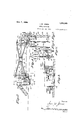
In describing the inventionin' detail, reference will be had to the accompanying d drawings forming part of this application wherein like characters denote correspondviews, and in which f Figure 1 illustrates aplan view of a erry go-round showing a device embody ing the invention;
Figure 2 illustratesa sectional view thereof;
Figure '3 illustrates a'sectional view on the line 3-3 of Fig 2; I I
Figure 4 illustrates "a sectional view on the'line' 4- of Fig. l with parts broken away and other parts omitted;
Figure 5' illustrates a view similar to Fig. 4 except that the parts are in different positions of adjustments; I
Figure 6 illustrates a detail view of 1 a modified car arresting device; and
Figure 7 illustrates a view in elevation of one 'ofthe faces of the arresting device d shown in Fig. 6, showing partsassociated with'i t.
The accompanying illustrate one embodiment of the invention and the inventor does not wish to be limited with respect [to the details, except as they may be specified by the annexed claims,
As illustrated'in the accompanying drawing, the base or framework or trellis 10 is circular, other configurations. a
A series 'of journalbearings or brackets 11 are located on the frame and journals of conical rollers 12, having flanges 12*" constituting guides, are rotatably "mounted o5 therein. j
Concentric with the framework just described, a track holding frame 13 is supplied by whichthe track is supported in an drawing is intended to although obviously it can have inclined position, the lowermost portion or point thereof being preferably in spaced relation to that end of the track" having the greatest elevation, and for convenience of illustration, the lowermost part of the track is indicated by the numeral 14, whcreasthat" portion of the. track having the greatest,
height is indicated by the numeral 15;
Suitable loading andfiunloading platforms with appropriate approaches and exitswill, of course, be includedas a. part of the structurefor convenifinceoffo-peration, bu-t'the inventor does 1 notiwish-to be limited vwith respect to these features their number,- or. their arrangement.
Awvheel is mounted n therollers and any suitable mechanism-may be provided for driving the frame andcausing it;to;rotate on a horizontal plane, r on: an approximately horizontal plane, and; in the present embodiment of 1 the invent-ion, the wheel has what mightberegarded [as a central section orhub 16, withflangesi 17 and 18. Radial bracesor spokes 19 are pro videdan-d they have; their inner; ends attached to the flanges 171and 18., There is an upper flanged ring 20 to which; the outer ends of the upper braces are connected- ;and a lower ring; 21 to which the outer' ends of the lower braces are connected. The-ring 21 is preferably in the nature-of :a channel iron whose lowerflangerides on the-rollers 12 during the rotation of the frame or wheel. Theiupper ringanddower ring are connected by a plurality. of ribs or strips 22 which arec-preferab ly-of metal and these, in the present embodiment of theinvention, are arranged in pairs and, constitute-guides.
An, arm oscillatesbetween themembers of each pair ofguides andthe inner end .of each arm is oscillatably connected to the hub 16,-as by a pivot 24 Eachyarm has a bracket 25 on its lower gside in which a roller 26 is journaled, and thesrolle'r travels on the track to which: reference has already been made, the said trackncting as a sup.- port for the arms as the frame or wheel is rotated.
In the interests'of clearness ofdescription and :to avoid alternative terms as designating the rotatable iframe or wheeh it will be hereafter-referred .to assa wheel-77, since it approaches a wheel in-:- its construction; and is rotatably supported...
A. car. 27' is suspended or. slung from;.z.each arm at its outer end andprefer b y each ear;isgloosely suspended rom-the, in
Each?- 23 cornprises :t we channel; bars other and the cliannel bars are conneetedtb'y a bolt 30 from which the car is suspended.
Cheek piecesiBlr andjz32iare connectec 5 to theschannel bars I re pect v y, and; converge iBFQZIlJOVGu. They areconnected:bya piv t 33 on which a piston rod 34: is oscillatable,
the said piston rod being connected to pisto1r35 that operates in a cylinder 36. The'cylinder is provided with trunnions 3'? and 38 that are journaled in brackets 39 secured in appropriate manner to the lower series of spokes 19 It is the purpose of the inventor that the mechanism just described shall operate as a cushioning device or somewhat in the nature of a dashpot wherein the descent of the piston in the cylinder compresses air. in the bottom. which serves to gradually arrest the descent of the arm to cushion the fall from the high end of the track to the plane approximately that of the low end of the track.
It will be apparent that an occupant of a car thatileaves the high end of the track and falls precipitously in an unsupported device will have a sensation .quite different from. those who occupy cars that are travelingon inclinedtracksin which the car is constantly supported. To aid in developing the descending sensation and imparting a thrill .to the ride, the car is caused to travel over. a pool of water-on a rela tively high elevation, from which the water escapes in a manner to simulate a. falls, and it.is the purpose of the. inventor that. the car shall descend or. fall just after the end of the pool has been reached and that the. car shall: descend practically parallel with the course of the water in its descent from. thehigher to the lower level. In the drawing, the pool is identified by the numeral 40, the partition over which the wat8].'.fi'OWS'iIO produce the falls 41, and the lower pool. to which thewater descends is; identified by thenumeral 42. Of course the relation of these pools and the fall to the elevated and depressed end of the track may bechanged to suit particular require ments, and the space available for the creation of the marine scene.
In, themodified device for cushioning the descent of the arm and the car, the lower spokes l9 oscillatably support guides 4 each of which has a zigzag channel in its inner face. The armsare arranged in pairs i-n the present embodiment of the invention, and the channels in the two faces are compl'ementah In his modificatioin an arm 4.4: has a hanger e5 oscillatably connected;to,it and the hanger is provided witlaapin or shaft- 46 on which roller 47 is rotatable, the said roller being of a size which will travel :in the Zigzag chain neland causethe: to descend more Slowly" than'it would if: the descent were unobstructed. This modified arm arresting device would give a somewhat: jarring or vibrating action to the descending; arm and the sensation resulting; from itsuse would be-diiferent from that of the cushioning: device shown inFigs. t-and i From an inspection of the drawing and i from "the foregoing ured.
description, it will apit a wheel isproperly' driven or rotated, it will carry the cars around the track, and" that when the' end of the track is reached the car will 'fall, although its descent will'be controlled in'or'der that the occupants of 'thecar will not be in- It is desirable,:of' course, that the be' allowed to descend to a parent that car should not greater extent on the arms't'o 'register with the upper surface of the lower end of the track, for it is the intention ofthe inventor that after vstantially circular with-a gap therein wherethe descent, the arms shall be immediately supported again by the track in "order that the cars may be elevated as the wheelrotates.
Figs. 4 and 5 provides for arrest-ing the piston or the descent of the arm by the action of air, it is understood that the inventor contemplates that spring cushioning means could be substituted as an equivalent mechanical device for accomplishing the same result as that contemplated by the use of the pneumatic device.
I claim:
1. A roundabout having a substantially circular track, a car carrying means adapted to be supported by the track and with relation to which track the said means travels, means adapted to be driven carrying the said first mentioned means with relation to the track, the said track having a gap where the said car carrying means is unsupported and into which gap the car carrying means descends precipitously, and means for arresting the car carrying means in its descent.
2. A roundabout having a substantially circular track, a car supporting element for traveling in engagement with the track whereby the said element is supported, means ror moving the said element around the track, the said track having a gap where the element is unsupported and into which gap the element descends precipitously, and means for arresting and cushioning the car carrying element in its descent.
3. In a roundabout, a track arranged substantially circular with a gap therein whereby two ends of the track are present, means for supporting the track on an incline whereby one end is materially higher than the other end, a car carrying element including means supported by the track, means for driving the car carrying element around the track until it runs from the high end of the track and from which it falls, and means for cushioning the fall of the said car carrying element in its descent.
4. A roundabout having a substantially circular track, a car carrying means adapted to be supported by the track and with relathan will permit the rollers While the cushion device as shown in thetrack, the said traclchaving a gap where the said car carrying mean-s is'unsupported andinto which gap; the car carryingineans descends precipitously, means for arresting the car carrying means in its descent, anda water-fall having its course of descent at the gapfin the track in a position back of the course traveled by the 'carbarr'ying means in'its descent. v
' 5. In a roundabout, a track arranged subby two ends of the track are present, means 't'or supporting the track on an incline whereby oneend is materially higher than the "other end, a' car carrying 'element'including means supported by the track, means for driving the car carrying element around the track until it runs from the high end of the track and from which it falls, means for cushioning the fall of the said car carrying element in its descent, and a water-fall having its course of descent at the gap in the track in a position back of the course traveled by the car carrying means in its descent.
6. A roundabout having a substantially circular track, a car carrying means adapted to be supported by the track and with relation to which track the said means travels, means adapted to be driven carrying the said first mentioned means with relation to the track, the said track having a gap where the said car carrying means is unsupported and into which gap the car carrying means descends precipitously, means for arresting the car carrying means in its descent, a simulated pool at the high end of the track and a simulated water-fall therefrom past which the car carrying means and the car descend when it leaves the track.
7. A roundabout having a substantially circular track, a car carrying means adapted to be supported by the track and with relation to which track the said means travels, means adapted to be driven carrying the said first mentioned means with relation to the track, the said track having a gap where the said car carrying means is unsupported and into which gap the car carrying means descends precipitously, and a water-fall having its course of descent at the gap in the track in a position back of the course traveled by the car carrying means in its descent. I
8. A roundabout having a substantially circular track, a car carrying means adapted to be supported by the track and with relation to which track the said means travels, means adapted to be driven carrying the said first mentioned means withirelation to the track, the said track having a gap where the said car carrying means is unsupported and into which gap the car carrying; means; descends precipitously, a-
the ear carrying meanscarriesthe car and, approximately parallel with the course of theWater-fall the car carrying, means descends precipitously.
9.- A roundabout comprising a. rotatably mounted frame, arms extending" radially therefrom and pivoted to the frameforlvertical movement, a track-substantially concentric with the periphery of the frame, said trackbeing; supported on an incline with a :gapbetween the highest and lowest portionsof thetraclgflrotatahlei devices; on the arms supported (by the track,- ears-suspended from. the arn 1s,, and; means, for cushioning thedeseent of,.-'tl1'e arms when the said arm supporting; device leayesthe track.
10. Aroundabout:comprising a rotatably mounted frame, arms, extending radially therefrom andnpiyotedito theframefor vertical mo em'en-t, a" track -substantially concentricwith. the periphery. of the frame, saidztraek; being supported on an incline With a gapi'betweenthe highestand lowest portions 5 of v' the: track,- rotatable devices. on therarmscwsupported:hy thetrack, cars suspendedfromthearmS, and means for cushioning, the descent of the arms W11 en unsupported. by, the trackv and for maintaining them in position to be engag eclvby the low end of the track as the frame rotates IVOB W; JONES.
Priority Applications (1)
| Application Number | Priority Date | Filing Date | Title |
|---|---|---|---|
| US683423A US1510941A (en) | 1923-12-29 | 1923-12-29 | Merry-go-round |
Applications Claiming Priority (1)
| Application Number | Priority Date | Filing Date | Title |
|---|---|---|---|
| US683423A US1510941A (en) | 1923-12-29 | 1923-12-29 | Merry-go-round |
Publications (1)
| Publication Number | Publication Date |
|---|---|
| US1510941A true US1510941A (en) | 1924-10-07 |
Family
ID=24743981
Family Applications (1)
| Application Number | Title | Priority Date | Filing Date |
|---|---|---|---|
| US683423A Expired - Lifetime US1510941A (en) | 1923-12-29 | 1923-12-29 | Merry-go-round |
Country Status (1)
| Country | Link |
|---|---|
| US (1) | US1510941A (en) |
Cited By (2)
| Publication number | Priority date | Publication date | Assignee | Title |
|---|---|---|---|---|
| DE1217829B (en) * | 1960-10-26 | 1966-05-26 | Norman Bartlett | Shock absorber system for carousel gondolas suspended on a rotating mast, partly running on the ground, partly free-floating |
| US20130130812A1 (en) * | 2009-11-17 | 2013-05-23 | Mack Rides Gmbh & Co. Kg | Rotating water amusement ride |
-
1923
- 1923-12-29 US US683423A patent/US1510941A/en not_active Expired - Lifetime
Cited By (4)
| Publication number | Priority date | Publication date | Assignee | Title |
|---|---|---|---|---|
| DE1217829B (en) * | 1960-10-26 | 1966-05-26 | Norman Bartlett | Shock absorber system for carousel gondolas suspended on a rotating mast, partly running on the ground, partly free-floating |
| US20130130812A1 (en) * | 2009-11-17 | 2013-05-23 | Mack Rides Gmbh & Co. Kg | Rotating water amusement ride |
| US8777766B2 (en) * | 2009-11-17 | 2014-07-15 | Mack Rides Gmbh & Co. Kg | Rotating water amusement ride |
| US9095780B2 (en) | 2009-11-17 | 2015-08-04 | Mack Rides Gmbh & Co. Kg | Rotating water amusement ride |
Similar Documents
| Publication | Publication Date | Title |
|---|---|---|
| US2294166A (en) | Amusement device | |
| US1510941A (en) | Merry-go-round | |
| US771322A (en) | Ball-coaster. | |
| US2828128A (en) | Amusement ride device | |
| US2203971A (en) | Amusement device | |
| US1791227A (en) | Merry-go-round | |
| US1583287A (en) | Roundabout | |
| US1354436A (en) | Amusement apparatus | |
| US1361449A (en) | Mechanical toy | |
| US1568424A (en) | Ferris wheel | |
| CN204182123U (en) | Revolving flying chair for amusement | |
| NL2022973B1 (en) | FLOAT ATTRACTION WITH CONTROLS FOR CONTROLLING THE Sway | |
| US1590845A (en) | Inclined merry-go-round | |
| US2399332A (en) | Amusement ride | |
| US1640038A (en) | Passenger car for amusement rides | |
| US2570981A (en) | Vertical axis circular swing | |
| US2841395A (en) | Occupant propelled roundabout | |
| US878400A (en) | Amusement device. | |
| US1518288A (en) | Amusement device | |
| US625074A (en) | weber | |
| US1651487A (en) | Amusement device | |
| US2200864A (en) | Roundabout | |
| US1564952A (en) | Rotary amusement device | |
| US898056A (en) | Amusement apparatus. | |
| US1466963A (en) | Amusement device |