US1508317A - Motorless aerial winged torpedo - Google Patents
Motorless aerial winged torpedo Download PDFInfo
- Publication number
- US1508317A US1508317A US382932A US38293220A US1508317A US 1508317 A US1508317 A US 1508317A US 382932 A US382932 A US 382932A US 38293220 A US38293220 A US 38293220A US 1508317 A US1508317 A US 1508317A
- Authority
- US
- United States
- Prior art keywords
- torpedo
- winged
- steering
- distance
- aerial
- Prior art date
- Legal status (The legal status is an assumption and is not a legal conclusion. Google has not performed a legal analysis and makes no representation as to the accuracy of the status listed.)
- Expired - Lifetime
Links
- 230000000087 stabilizing effect Effects 0.000 description 8
- 241000251729 Elasmobranchii Species 0.000 description 7
- XLYOFNOQVPJJNP-UHFFFAOYSA-N water Substances O XLYOFNOQVPJJNP-UHFFFAOYSA-N 0.000 description 7
- 210000000056 organ Anatomy 0.000 description 5
- 239000000725 suspension Substances 0.000 description 5
- 230000005484 gravity Effects 0.000 description 3
- 230000001105 regulatory effect Effects 0.000 description 3
- 230000001276 controlling effect Effects 0.000 description 2
- 238000000034 method Methods 0.000 description 2
- 230000001174 ascending effect Effects 0.000 description 1
- 238000005452 bending Methods 0.000 description 1
- 238000007664 blowing Methods 0.000 description 1
- 230000001419 dependent effect Effects 0.000 description 1
- 238000007598 dipping method Methods 0.000 description 1
- 238000004880 explosion Methods 0.000 description 1
- 239000002360 explosive Substances 0.000 description 1
- 230000004048 modification Effects 0.000 description 1
- 238000012986 modification Methods 0.000 description 1
- 230000002028 premature Effects 0.000 description 1
- 230000000284 resting effect Effects 0.000 description 1
Images


Classifications
-
- F—MECHANICAL ENGINEERING; LIGHTING; HEATING; WEAPONS; BLASTING
- F42—AMMUNITION; BLASTING
- F42B—EXPLOSIVE CHARGES, e.g. FOR BLASTING, FIREWORKS, AMMUNITION
- F42B17/00—Rocket torpedoes, i.e. missiles provided with separate propulsion means for movement through air and through water
Definitions
- loTonLsss Azam. wmen Tonrzno mma may 2q., 1920 5 sheets-sheet 1 /V VE N TORS, GA: 7a4/v0 ,An Tuna C poc C0,
- Aerial bombardments must often be carried out against strongly defended places as cities or other important points provided) with antiaerial defence, or against naturally strong places supplied with their own means of defence as fortified positions, batteries, warships ⁇ and the like.
- the present invention refers toV aerial bombs and torpedoes that incases as the aforesaid may be dropped from aircraft (airships and aeroplaneslupon targets that are out of their vertical line, even at a great distance.
- the bomb shaped almost like a torpedo. or exactly like it when it is to be used against ships, and provided with steering surfaces which can be adjusted during its flight, is also supplied with supporting surfaces or wings shaped like those of an aeroplane allowing it to follow in a sliding flight a preestablished course up to a distance just enough to reach'I5 the target which is to be hit, or to descend to the surface of the water to lay down the torpedo which must afterwards follow its way until it reaches the ship to loe torpedoed.
- the aotin of the device which control the rudders can be made dependent on any of the variable elements along the'way: for instance on the time of the fall, on the length of the way covered, on the pressure of the air, on the speed reached, or on the angle that the longitudinal axis of the torpedo forms the vertical line of descent.
- the torpedo In a second time the torpedo, righted by the de th rudders, covers a trajectory slightly inc ⁇ ned, in asteady sliding 'iiight until it reaches the target; the length of this second distance depends on the distance of the target itself and must be regulated every time if not employing torpedoes destined to be dropped from a constant distance from the target.
- the operation is simplified when the taret is a shipagainst which a torpedo must e launched, for in such a case the descent on the wings may be limited to its flight as far as to reach the surface of the sea where, as it will be explained hereunder, the torpedo abandonsits winged sup-port and begins its submerged course in the rusual way towards ⁇ the target.
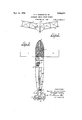
- Fig. 1 shows a typical form of the tra- 'l ietory
- Fig. 2 is a horizontal axial section of the torpedo
- FIG. 3 is a rear view in elevation of same;
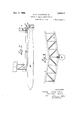
- Flg. 4 shows a usual aerial torpedo oarr1ed by an independent winged support;
- Fig. 5 shows a top view of a torpedo carried kby an independent winged support whlch is seen in section for better showing the arrangement of the interior;
- Figs. 6, .7 and 8 show a top view, a side and a front elevation respectively of a modification of the torpedo in an independent winged support;
- Fig. 9 1s a detail of the control organs Ofltthe steering surfaces of the winged sup P0 s Fig. 10 is a detail of the attachment of the torpedo according to Figs. 6- 8 to the wlnged'support,
- the aerial torpedo, Fig.-2 in its more general form, consi ts of a casing 1 shaped like a torpedo body and carrying in its head the explosive charge 2 with vits fusee 3.
- bearing surfaces 4 which, to lessen the encumbrance are biplane and arranged in the shape ⁇ o an open V towards the upper lIart so as to concur in ensuring the lateral stability.
- the steering surfaces are mounted on the tail of the torpedo-shaped body behind the usual cross shaped fins and comprise a depth rudder 5 and a steering rudder 6.
- the steering rudder 6 is connected to the rod of the piston of a compressed air auxiliary motor 12 fed by a reservoir 13 and controlled by a spring gyroscope 14 of the same kind as those used for similar purposes in torpedoes so that it is not necessary to describe it here in more in detail.
- Both of the two stabilizing fins 15 show a little window to allow free passage to tlie'blades ofthe distance measuring propeller 16, which, in the example illustrated in the drawing constitutes the organ that, in connection with the distance covered, must operate the depth rudder.
- a cam 2O conveniently shaped in accordance with the course that the torpedo must follow.
- the suspension system is preferably sup# ported on a. revolving pivot so as to allow that the dropping action may take place in any direction whatsoever without having to change the course of the aircraft if the target should not be on its line of flight.
- the suspension device As soon as the aeroplane, or the airship, has reachedpthe distance required from the target, the suspension device is released and while the torpedo gets free from its fastenings, the steering gyroscope whose spring had been wound up beforehand, begins to work.
- the steering cam keeps the rudders in the normal position, even while it continues to advance with a uniformv motion along the screwthreaded shaft.
- the cam operates the rudders so as to cause the bending of the trajectory downwards, i. e., along the course s3 which corresponds to the horizontal distance da'.
- the torpedo and its rudders are in such a position that the wing action is stopped and the torpedofalls vertically upon the target F, without changinrr its course any more whatever the height -hmay be.
- the torpedoes already existing and destined to be dropped vertically may be useful in practice to make use of the torpedoes already existing and destined to be dropped vertically.
- the result may be obtained by building separately the torpedo-shaped body with the winged supporting surface, the stabiliz- .ing surfaces, and the steering organs, and
- the torpedo 26 is introduced into the torpedo-shaped casing 1, formed of an external winged sheath-Fig. -in the same manner as in a torpedo launching tube, and it maybe extracted therefrom at the moment in which the wing surfaces 4 meet with the water which, by its resistance stops them, in the same way as it issues from the tube above mentioned, when it is being launched, and it is in that moment therefore that enter into action, in the manner already known, the gyroscope and the propelling apparatus which is to carry it upon the target, free from whatsoever appendages.
- FIGs. 6, 7 and 8. A very convenient form of connection of the torpedo with the winged support is that shown in Figs. 6, 7 and 8. 'As it may be seen, the torpedo-shaped bodv 1 of the sheath is substituted with a tube 27 which constitutes in the same time the compressed air tank for the gyroscope auxiliary-motor, and the connection of the bearing biplane surface 4 with the stabilizing device 15-28 and caudal steering surfaces.
- the depth rudder may be omitted as a separate element and formed into one piece together with the horizontal stabilizing device 15 conveniently sloping.
- the suspension of the torpedo to the winged support is obtained by means of a pin 29 passing through holes 'made in an eX- tension or short dorsal fin 30 with which the torpedo is supplied, Fig. 10, and in the cheeks of a saddle-shaped seat or upset cradle 31 carried by the biplane cell.
- the saddle-shaped seat is enough to keep in its place the torpedo, however, another seat 32 Fig. 7, placed under the end of tube 27 and resting on the vertical stabilizing fin 33 of the torpedo insures the rigidity -of the con nection.
- the torpedo plunges first into the sea and then follows the winged support: the resistance of the pin 29 is regulated in such a way so as to ensure the breaking through the resistance that the water makes against the wings, thus the torpedo gets free while the gyroscope and the propelling apparatus begin to work and runs towards the target leaving behind itself the winged support.
- An aerial torpedo to be dropped from an aircraft upon a target lying far from the vertical line of said aircraft and comprising a body with supporting wings, a depth rudder provided on the body, a distance measuring propeller, a cam member, means for operating the cam from the measuring propeller, and means controlled by the cam member for operating said rudder.
Landscapes
- Engineering & Computer Science (AREA)
- Chemical & Material Sciences (AREA)
- Aviation & Aerospace Engineering (AREA)
- Combustion & Propulsion (AREA)
- General Engineering & Computer Science (AREA)
- Control Of Position, Course, Altitude, Or Attitude Of Moving Bodies (AREA)
Description
sem., g, '1924, Lsosl 7 G. A. cRocco ET Al.
loTonLsss Azam. wmen Tonrzno mma may 2q., 1920 5 sheets-sheet 1 /V VE N TORS, GA: 7a4/v0 ,An Tuna C poc C0,
Sept, 9 ,508,317
G. A. cROCco ET 'AL mo'roRLass AERIAL WINGED Tomzno um May 2Qf 1920 l5 lsnee's-snewz z l/VVE/VTURS,
Gas nwo ARTURO CRocco,
ALEsANDRo Gu/Dom, 2,5 6,, 47' TOR/VE V5 Sepa.. g A1924. 1,508,311
G. A. CROCCO ET AL v HOTORLESS AERIAL WINGED TORPEDO 5 sheets-sheet' F1194 Nay 20 4 5 .OL v/ rHw R m66 m v o N WR w o RM AM 0S Nw MA M G Sept 9 G. ,A. cRocco ET AL MOTORLESS AERIAL WINC'ED TORPEDO mlm my 20, 1920 5 sneetjs-sheez 5 /m/E/v To/as Ann/Ro CRocco,
GAETA/v0 ALESSANDRO GU/Do/w;
Patented Sept. 9, 1924.
UNITED STATES PATENT OFFICE.
i MOTOR/LESS AERIAL WINGED TORPEDO.
Application led May 20,
To all whom t may concern:
Be it known that We, GAETANO ARTURO CRoooo, colonel of the Italian Army, and ALESSANDRO GUIDoNI, engineer, .both subjects of the King of Italy, and residing at Rome, in the Kingdom of Italy, have invented certain new and useful Improvements in M0- torless Aerial Winged Torpedoes, of which the following is'a description.
Aerial bombardments must often be carried out against strongly defended places as cities or other important points provided) with antiaerial defence, or against naturally strong places supplied with their own means of defence as fortified positions, batteries, warships` and the like.
In such cases it is difficult for aircraft to approach thevertical of the target and remain there permanently in order't carry out the bombardmentand this must necessarily be done by keeping out of the vertical line of the target itselfand possibly at a great distance therefrom.
The present invention refers toV aerial bombs and torpedoes that incases as the aforesaid may be dropped from aircraft (airships and aeroplaneslupon targets that are out of their vertical line, even at a great distance.
For such a purpose the bomb, shaped almost like a torpedo. or exactly like it when it is to be used against ships, and provided with steering surfaces which can be adjusted during its flight, is also supplied with supporting surfaces or wings shaped like those of an aeroplane allowing it to follow in a sliding flight a preestablished course up to a distance just enough to reach'I5 the target which is to be hit, or to descend to the surface of the water to lay down the torpedo which must afterwards follow its way until it reaches the ship to loe torpedoed.
lVith the above mentioned objects in view the aerial torpedo, according to the present invention, is provided with controlling means which during ,its flight ensure the steadiness of the course and limit the range of the flight as required; and, differently from other devices of the same kind, it does not carry propelling machinery and is pi'opelled solelylby the action of its weight. 'V
Besides, for the purpose of reducing to a minimum the drift due to the wind eventu- 1920. Serial No. 382,932.
ally blowing and also for reducing the dimensions and the incumbrance of the apparatus, to its bearing wings a very limited surface is assigned, so that to the gliding or sliding flight corresponds a very high speed, and, in order that this speed may be attained in a short time, the arrangement is such that from the very beginning of its Hight the torpedo falls almost vertically -until it acquires the necessary speed while losing height, and, when therequired speed has been reached, begin to enter into action certain devices which, acting upon the steering surfaces,- depth rudders,-it will vary the position of them in such a way as to oblige the craft to proceed on` its way in a` sliding flight.
If there were not provided controlling devices o-f the depth rudders and the latter were from the very beginning of the launching arranged in the position of the sliding flight, it is known that the apparatus would tend to acquire, in sliding downwards, an excessive speed which would cause it to rise agairy'afterwards and successively roceed according to a wavy trajectory of escending and ascending movements in wide sinuosities, Y
The action of-the depth rudder set at the convenient angle and in due time, controlsv therefore the descent bringing in va Ver,v short time the' apparatus in the proper position for thefsliding flight.
The aotin of the device which control the rudders can be made dependent on any of the variable elements along the'way: for instance on the time of the fall, on the length of the way covered, on the pressure of the air, on the speed reached, or on the angle that the longitudinal axis of the torpedo forms the vertical line of descent.
In the form of execution ofthe torpedo which will be described by `-way of example, there will be shown a device whose action is controlled by the length of the dittance covered: it is understood, however, that any of the other methods mentioned above might start its flight by dipping* down in rapid descent for a distance sufcient to attain just as well be conveniently adopted as they x the necessary speed, a distance-which is always the same whatever the distance from the target and the height of the aircraft, -from which it is dropped, may be.
In a second time the torpedo, righted by the de th rudders, covers a trajectory slightly inc `ned, in asteady sliding 'iiight until it reaches the target; the length of this second distance depends on the distance of the target itself and must be regulated every time if not employing torpedoes destined to be dropped from a constant distance from the target.
At the end of this second stretch of its course the torpedo bends its trajectory downwards and descends vertically. In order to secure this result it is necessary to produce a considerable centripetal force by arranging the wings at an angle of negative incidence and this may be obtained by operating the depth rudder always set in the aforesaid manner in connection with one of the elements variable along the course.
It is understood that the result obtained by operating the rudders can be equally reachedl by varying the incidency of the wings. Whichever the method followed be, when the trajectory of the bomb is thus reduced to be vertical, it needs a third action ofthe rudders in order to preserve the obtained verticality of the falling line.
The operation is simplified when the taret is a shipagainst which a torpedo must e launched, for in such a case the descent on the wings may be limited to its flight as far as to reach the surface of the sea where, as it will be explained hereunder, the torpedo abandonsits winged sup-port and begins its submerged course in the rusual way towards `the target.
n the drawing attached hereto illustratlng schematically a form of execution of the aerial torpedo, according to the present inventlon:
Fig. 1 shows a typical form of the tra- 'l ietory;
Fig. 2 is a horizontal axial section of the torpedo;
3 is a rear view in elevation of same; Flg. 4 shows a usual aerial torpedo oarr1ed by an independent winged support;
Fig. 5 shows a top view of a torpedo carried kby an independent winged support whlch is seen in section for better showing the arrangement of the interior;
Figs. 6, .7 and 8 show a top view, a side and a front elevation respectively of a modification of the torpedo in an independent winged support; i
Fig. 9 1s a detail of the control organs Ofltthe steering surfaces of the winged sup P0 s Fig. 10 is a detail of the attachment of the torpedo according to Figs. 6- 8 to the wlnged'support,
The aerial torpedo, Fig.-2, in its more general form, consi ts of a casing 1 shaped like a torpedo body and carrying in its head the explosive charge 2 with vits fusee 3.
To the casing are attached the bearing surfaces 4 which, to lessen the encumbrance are biplane and arranged in the shape `o an open V towards the upper lIart so as to concur in ensuring the lateral stability. On
the other side both the size of thel wingsV and thatof the steering'surfaces, is rather limited owingto the high speed assigned to this torpedo in its sliding flight.
The steering surfaces are mounted on the tail of the torpedo-shaped body behind the usual cross shaped fins and comprise a depth rudder 5 and a steering rudder 6.
fThrough an articulated system of links and angle levers 7--8--9-10-11 the steering rudder 6 is connected to the rod of the piston of a compressed air auxiliary motor 12 fed by a reservoir 13 and controlled by a spring gyroscope 14 of the same kind as those used for similar purposes in torpedoes so that it is not necessary to describe it here in more in detail.
Both of the two stabilizing fins 15 show a little window to allow free passage to tlie'blades ofthe distance measuring propeller 16, which, in the example illustrated in the drawing constitutes the organ that, in connection with the distance covered, must operate the depth rudder.
For this purpose the shaft 17, on which the propeller is keyed by means of a set of gears designed to reduce the number of revolutions, transmits its movement to anoth"'r`shaft 19 bearing a screw-thread up to a c rtain portion of its length. Along this thread slides, during the Vrevolving motion of the propeller a cam 2O conveniently shaped in accordance with the course that the torpedo must follow.
Againstthe cam rests, with an antifriction roller, one of the arms of an angle lever 21, the other arm of'which is continually pulled by a spring 22 and at the other end connected, through an articulated system of links and levers 23--24-25 with the depth rudder 5.
The working of the torpedo is as follows :l
through a convenient suspension system it is preferably carried at the lower side of the aircraft in a horizontal position, so that, during the flight, its weight is partially supported by the action of the wind which impinges against the wings 4.
The suspension system is preferably sup# ported on a. revolving pivot so as to allow that the dropping action may take place in any direction whatsoever without having to change the course of the aircraft if the target should not be on its line of flight.
As soon as the aeroplane, or the airship, has reachedpthe distance required from the target, the suspension device is released and while the torpedo gets free from its fastenings, the steering gyroscope whose spring had been wound up beforehand, begins to work.
In the first portion SL of the trajectory, Fig. 1, extending' from the starting point A whence the fall begins, up to point B at which the torpedo after having reached the required speed starts with the regular sliding Hight the distance-measuring propeller shifting the cam 20 operates the depth rudder in such a way as to cause the passage of the torpedo from its initial to its normal flying position. A
During the sliding fiight, that is to say, within the distance s2. comprised between point B in which it starts and point C whence its downward movement begins, the steering cam keeps the rudders in the normal position, even while it continues to advance with a uniformv motion along the screwthreaded shaft.
Lastly, when the torpedo has reached point C, that is to say after having covered the distance s1}s2, corresponding to the horizontal course dft-d2, the cam operates the rudders so as to cause the bending of the trajectory downwards, i. e., along the course s3 which corresponds to the horizontal distance da'. At the end of this bent portion, at point E, the torpedo and its rudders are in such a position that the wing action is stopped and the torpedofalls vertically upon the target F, without changinrr its course any more whatever the height -hmay be.
In order to regulate the course of the torpedo it will suffice to know the total horizontal distance D2051 -l-d'Z-j-d, interceding between the vertical line AAof the aircraft at the moment in which it is dropped and that of the target F. As the sum of .the distances dfi-032 is an experiment-al fixed quantity independent from the distance of the target and the height of the aircraft which drops the torpedo, the position of the cam is regulated according to the distance (l, which is to be covered during the sliding Hight.
This distance is assumed to be aI preestablished and invariable one in the example given in the drawing, but it will be easily understood that the steering cam 2O may be shaped in such a way so as to enable to change at will the length of the distance corresponding thereto.
In the same manner the movement of the distance measuring propeller mav be caused to release, by one of the known ways, a safety device designed to prevent the premature explosion of the torpedo while itis still near the aircraft.
In the abo-ve said it has been assumed, for greater generality, that the case referred to an aerial torpedo built completely anew. But
it may be useful in practice to make use of the torpedoes already existing and destined to be dropped vertically. The result may be obtained by building separately the torpedo-shaped body with the winged supporting surface, the stabiliz- .ing surfaces, and the steering organs, and
by applying afterwards to this torpedo shaped body, instead of charge 2 contained within-as shown in Fig. 2- a complete torpedo 26 as shown in Fig. 4. The other organs, with which the torpedo-shaped body is provided, bearing surfaces 4, compressed a1r tank 13, gyro-scope with its auxiliary motor and movable steering cam schematically shown by G and S, and the stabilizing device at the tail with the steering surfaces, remain unaltered. This arrangement, which is already very convenient for common bombs and torpedoes, for it allows to apply to the winged support torpedoes ready for use, and also of different patterns, eventually detachable from the winged support towards the end of their course, is mo-st important in the case in which it is necessary to drop the torpedo against a ship for it allowsV of using the torpedo, a very com plicated device, just as it is without change in any of its parts.
The torpedo 26 is introduced into the torpedo-shaped casing 1, formed of an external winged sheath-Fig. -in the same manner as in a torpedo launching tube, and it maybe extracted therefrom at the moment in which the wing surfaces 4 meet with the water which, by its resistance stops them, in the same way as it issues from the tube above mentioned, when it is being launched, and it is in that moment therefore that enter into action, in the manner already known, the gyroscope and the propelling apparatus which is to carry it upon the target, free from whatsoever appendages.
It is to be remarked moreover that in the case of a torpedo to be launched against a ship, the only parts which are needed of the whole trajectory shown in Fig. 1, are the A portion s, and, eventually, part of the sliding flight 82 if by change the apparatus were too high at the moment the torpedo is dropped. In this first part of the trajectory the steering organs connected with the winged casing 1, work in the identical manner of that explained before in describing the trajectory represented at Fig. 1.
A very convenient form of connection of the torpedo with the winged support is that shown in Figs. 6, 7 and 8. 'As it may be seen, the torpedo-shaped bodv 1 of the sheath is substituted with a tube 27 which constitutes in the same time the compressed air tank for the gyroscope auxiliary-motor, and the connection of the bearing biplane surface 4 with the stabilizing device 15-28 and caudal steering surfaces.
These are simplified for, supposing practically to limit the speed of Hight to values near that of the aircraft which drops the device, the depth rudder may be omitted as a separate element and formed into one piece together with the horizontal stabilizing device 15 conveniently sloping.
As a-moveable piece there remains only the steering rudder 6 fastened to the vertical stabilizing surface 8 and therefore the movable steering cam 20, is done away with as well as the distance measuring propeller and there remains no other device but the steering gyroscope 14 which, with the compressed air auxiliary motor, controls in the usual manner the flight course rudder 6 during the descent.
The suspension of the torpedo to the winged support is obtained by means of a pin 29 passing through holes 'made in an eX- tension or short dorsal fin 30 with which the torpedo is supplied, Fig. 10, and in the cheeks of a saddle-shaped seat or upset cradle 31 carried by the biplane cell. The saddle-shaped seat is enough to keep in its place the torpedo, however, another seat 32 Fig. 7, placed under the end of tube 27 and resting on the vertical stabilizing fin 33 of the torpedo insures the rigidity -of the con nection.
In its fall the torpedo plunges first into the sea and then follows the winged support: the resistance of the pin 29 is regulated in such a way so as to ensure the breaking through the resistance that the water makes against the wings, thus the torpedo gets free while the gyroscope and the propelling apparatus begin to work and runs towards the target leaving behind itself the winged support.
The disengaging devices necessary to initiate such a working have not been included in the drawing for simplicitys sake.
Claimsl. An aerial torpedo to be dropped from aircraft upon targets lying distant from the vertical line of said aircraft, upon which targets it shall reach through the sole action of the gravity, comprising bearing surfaces sufficient to support it when in sliding Hight, adjustable steering surfaces and means acting in correspondence to the distance traversed, and which control the position of said steering surfaces during the Hight so as to steer .the torpedo along a predetermined route in a vertical plane, the steering surfaces being successively set in such a manner that, as soon as the torpedo is left to itself,
it descends almost vertically in order to acquire a high speed with which to proceed then in a sliding Hight until it reaches the vicinity of the target.
2. An aerial torpedo to be dropped from an aircraft upon a target lying far from the vertical line of said aircraft and comprising a body with supporting wings, a depth rudder provided on the body, a distance measuring propeller, a cam member, means for operating the cam from the measuring propeller, and means controlled by the cam member for operating said rudder.
3., The combination of a winged support with stabilizing devices and steering surfaces, a tubular casing carried by said support, a complete self-moving water torpedo with steering and propelling means contained in said casing, means as a distance measuring propeller acting on the steering means of the winged support to control its course while it moves downward under the action of the gravity alone, and `means to allow the torpedo leaving its casing and to start against a Hoating target, as soon as the whole deviceplunges into the water.
4. The combination of a winged support with stabilizing devices and steering surfaces, a complete self-moving water torpedo with steering and propelling means freely suspended beneath said winged support, a breakable pin connecting the torpedo to the winged support, means as a distance measuring propeller acting on the steering means of the winged support to control its course while, under the action of the gravity alone, it moves downward against a Hoating target, the suspension pin breaking and releasing the torpedo when the wings come into contact with the water.
In testimony whereof we affix our signatures in the presence of two witnesses.
Signed by the first named applicant at Rome, in the Kingdom of Italy, this 31st day of March, 1920.
GAETANOy ARTURO CROCCO.
Witnesses yfor` 'the first named applicant, Gaetano Arturo Crocco:
LETTERN LUnsoUTAs, ANTONIO LUBsoUTAs.
Signed by the second named applicant at Washington, in the District of Columbia, this 17th day of May, 1920.
ALESSANDRO GUIDONI.
Witnesses for the second named applicant, Allesandro Guidoni:
GIUSEPPE A. F. SPARARRE. W. E. BECK, Jr.
Priority Applications (1)
| Application Number | Priority Date | Filing Date | Title |
|---|---|---|---|
| US382932A US1508317A (en) | 1920-05-20 | 1920-05-20 | Motorless aerial winged torpedo |
Applications Claiming Priority (1)
| Application Number | Priority Date | Filing Date | Title |
|---|---|---|---|
| US382932A US1508317A (en) | 1920-05-20 | 1920-05-20 | Motorless aerial winged torpedo |
Publications (1)
| Publication Number | Publication Date |
|---|---|
| US1508317A true US1508317A (en) | 1924-09-09 |
Family
ID=23511012
Family Applications (1)
| Application Number | Title | Priority Date | Filing Date |
|---|---|---|---|
| US382932A Expired - Lifetime US1508317A (en) | 1920-05-20 | 1920-05-20 | Motorless aerial winged torpedo |
Country Status (1)
| Country | Link |
|---|---|
| US (1) | US1508317A (en) |
Cited By (5)
| Publication number | Priority date | Publication date | Assignee | Title |
|---|---|---|---|---|
| US2423090A (en) * | 1943-08-25 | 1947-07-01 | Fink Rudolph | Controllable gliding attachment for bombs |
| US2432421A (en) * | 1942-01-08 | 1947-12-09 | John H Homrighous | Directional control for bombs |
| US2517860A (en) * | 1946-10-22 | 1950-08-08 | Robert H Forgy | Device for protecting the occupants and contents of vehicles |
| US2943568A (en) * | 1944-12-18 | 1960-07-05 | Henry C Pavian | Stabilizing device |
| US2992794A (en) * | 1950-12-13 | 1961-07-18 | William H A Boyd | Guided missile |
-
1920
- 1920-05-20 US US382932A patent/US1508317A/en not_active Expired - Lifetime
Cited By (5)
| Publication number | Priority date | Publication date | Assignee | Title |
|---|---|---|---|---|
| US2432421A (en) * | 1942-01-08 | 1947-12-09 | John H Homrighous | Directional control for bombs |
| US2423090A (en) * | 1943-08-25 | 1947-07-01 | Fink Rudolph | Controllable gliding attachment for bombs |
| US2943568A (en) * | 1944-12-18 | 1960-07-05 | Henry C Pavian | Stabilizing device |
| US2517860A (en) * | 1946-10-22 | 1950-08-08 | Robert H Forgy | Device for protecting the occupants and contents of vehicles |
| US2992794A (en) * | 1950-12-13 | 1961-07-18 | William H A Boyd | Guided missile |
Similar Documents
| Publication | Publication Date | Title |
|---|---|---|
| US12078459B1 (en) | Methods for extended-range, enhanced-precision gun-fired rounds using g-hardened flow control systems | |
| US6286410B1 (en) | Buoyantly propelled submerged canister for air vehicle launch | |
| US2470120A (en) | Method of bombing from fast moving planes | |
| US4408737A (en) | Method and apparatus enabling a horizontal landing of a flying body | |
| KR890000530B1 (en) | Armory delivery system and method comprising a remotely controlled or programmable aircraft equipped with a yaw turn guidance system | |
| US6471159B1 (en) | Airship shaped space craft | |
| CN104691748A (en) | Gun-launched unmanned helicopter and expansion method thereof | |
| US3000597A (en) | Rocket-propelled missile | |
| US1508317A (en) | Motorless aerial winged torpedo | |
| US20150284080A1 (en) | Special forces replenishment vehicle | |
| US2390677A (en) | Catapult device for autonomous aerial torpedoes | |
| US3298639A (en) | Gliding parachute | |
| US2434187A (en) | Stabilizing and steering of aerial torpedoes or bombs | |
| US2285574A (en) | Aerial bomb | |
| GB582845A (en) | Improvements in or relating to marine torpedoes launched from aircraft | |
| US1297273A (en) | Aerial torpedo or mine. | |
| US1209625A (en) | Torpedo. | |
| GB582841A (en) | Improvements in or relating to aerial bombs | |
| RU2796086C1 (en) | Rocket glider with homing underwater projectile | |
| Fujiwara et al. | Flight plan and flight test results of experimental SST vehicle NEXST-1 | |
| US3038406A (en) | Mooring device | |
| US431210A (en) | Subaquatic projectile | |
| RU2716515C1 (en) | Aircraft with additional dropping wing | |
| US818987A (en) | Automobile torpedo. | |
| US1287158A (en) | Flying-machine. |