US1491663A - Sand-blast apparatus - Google Patents
Sand-blast apparatus Download PDFInfo
- Publication number
- US1491663A US1491663A US510462A US51046221A US1491663A US 1491663 A US1491663 A US 1491663A US 510462 A US510462 A US 510462A US 51046221 A US51046221 A US 51046221A US 1491663 A US1491663 A US 1491663A
- Authority
- US
- United States
- Prior art keywords
- barrel
- sand
- castings
- yoke
- latch
- Prior art date
- Legal status (The legal status is an assumption and is not a legal conclusion. Google has not performed a legal analysis and makes no representation as to the accuracy of the status listed.)
- Expired - Lifetime
Links
- 238000005266 casting Methods 0.000 description 12
- 239000004576 sand Substances 0.000 description 3
- 238000010276 construction Methods 0.000 description 2
- MXBCYQUALCBQIJ-RYVPXURESA-N (8s,9s,10r,13s,14s,17r)-13-ethyl-17-ethynyl-11-methylidene-1,2,3,6,7,8,9,10,12,14,15,16-dodecahydrocyclopenta[a]phenanthren-17-ol;(8r,9s,13s,14s,17r)-17-ethynyl-13-methyl-7,8,9,11,12,14,15,16-octahydro-6h-cyclopenta[a]phenanthrene-3,17-diol Chemical compound OC1=CC=C2[C@H]3CC[C@](C)([C@](CC4)(O)C#C)[C@@H]4[C@@H]3CCC2=C1.C1CC[C@@H]2[C@H]3C(=C)C[C@](CC)([C@](CC4)(O)C#C)[C@@H]4[C@@H]3CCC2=C1 MXBCYQUALCBQIJ-RYVPXURESA-N 0.000 description 1
- 241000320892 Clerodendrum phlomidis Species 0.000 description 1
- NGPDZEACIWDCKX-UHFFFAOYSA-N Tauremesin Natural products CC1(O)C=CC(=O)C2(C)C1C1OC(=O)C(C)C1CC2 NGPDZEACIWDCKX-UHFFFAOYSA-N 0.000 description 1
- NGPDZEACIWDCKX-DHKWMEDESA-N Tauremizin Natural products C([C@@]1(O)C)=CC(=O)[C@@]2(C)[C@H]1[C@H]1OC(=O)[C@@H](C)[C@@H]1CC2 NGPDZEACIWDCKX-DHKWMEDESA-N 0.000 description 1
- NGPDZEACIWDCKX-WUDKWMPASA-N Vulgarin Chemical compound C([C@]1(O)C)=CC(=O)[C@@]2(C)[C@H]1[C@H]1OC(=O)[C@@H](C)[C@@H]1CC2 NGPDZEACIWDCKX-WUDKWMPASA-N 0.000 description 1
- 238000005422 blasting Methods 0.000 description 1
- 239000000428 dust Substances 0.000 description 1
- 230000001788 irregular Effects 0.000 description 1
- 230000004048 modification Effects 0.000 description 1
- 238000012986 modification Methods 0.000 description 1
Images
Classifications
-
- B—PERFORMING OPERATIONS; TRANSPORTING
- B24—GRINDING; POLISHING
- B24C—ABRASIVE OR RELATED BLASTING WITH PARTICULATE MATERIAL
- B24C3/00—Abrasive blasting machines or devices; Plants
- B24C3/18—Abrasive blasting machines or devices; Plants essentially provided with means for moving workpieces into different working positions
- B24C3/26—Abrasive blasting machines or devices; Plants essentially provided with means for moving workpieces into different working positions the work being supported by barrel cages, i.e. tumblers; Gimbal mountings therefor
- B24C3/28—Apparatus using nozzles
Definitions
- Our invention relatesto sand blast apparatus, and particularly to apparatus of the ⁇ rotary barrel type,
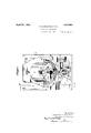
- the object of lour invention is to provide a tilting barrel having certain features: of improvement in construction and operationhereinafter pointed out or illustrated in the accompanying drawings, in which 4 o Fig.V 1 is a broken elevation of an apparapus in which our invention is embodied in one orm;
- Fig. 2 is a broken section on the line 2-2, Fig. 1;
- Fig. 3 is a section on the line 3-3, Fig. 1.
- thev present blast barrel 5 is housed within a casing 6, in which suitable openings, not shown, are provided for the introduction and removal of the castings.
- a sand-blast nozzle 7 also projects into the 59 casing in suitable position to operate upon the castings during the rotation of the barrel.
- the barrel is pivotally supported on opposite arms of the yoke 8 by means of trunnions 9.
- the yoke in turn is carried by an inclinedhollow shaft 10, to which a rotary motion is imparted through the bevel gear 11 fast on the shaft and meshing with a bevel pinion 12, on the shaft of which are fast and loose belt pulleys 13 and 14C.
- Both 0 bearings 15 and 16 for the shaft lie outside the casings and are thus protected from the dust and grit therein.
- the bearing vsupport may be of any suitable character, that shown being of simple form and comprising a casting, the leg 17 ot which carries the bearing 15, and is longer than the leg 18 which carries the bearing 16.
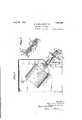
- an arcuate yokey 19 having a center ⁇ of curvature substantially 5 co-axial with the trunnions 9, but lying in a plane substantially at right angles to that of the barrel supporting fork 8. At suitable points in the yoke 19 apertures 20 are formed to receive the ,lathing bar 21- The.
- the stem 23 extends through the lower endlof the shaft 1() and carries a grooved pulley 24 engaged by a latch shifter 25.
- the latter is l fast'ona spindle 25 pivoted on lthe lower portion of the leg 18 of the base casting.
- crank arni 27 fast on the shaft 26 serves to rockthe latch shifter.
- Any suitable means may be used to actuate the crank arm'27', such for instance as a connecting rod 28, which may be operated by hand, or by power, as desired.
- a barrel for the reception of castings, or the like means having a fixed inclination Yfor Asupporting and rotating the barrel, and
- an inclined spindle for supporting and rotating'tlie barrel, and cooperating latch! ing elements on said barrel and support for holding the barrel With its axis at different inclinations to the axis of the'spindle in combination with a stationary casing surrounding the barrel, and Within which it rotates, and a Vblast nozzle adaptedwto play upon the castings Within the barrel during the rotation of Vthe latter.
- y 'Y In testimony Whereotwe have signed-our naines to this specification.
Landscapes
- Engineering & Computer Science (AREA)
- Mechanical Engineering (AREA)
- Finish Polishing, Edge Sharpening, And Grinding By Specific Grinding Devices (AREA)
Description
Apri 22 1924.
1,491,663 C. E. BILLINGS ETvAL SAND BLAST APPARATUS Filed oct. 26.
1921 2 sheets-sheet 1 April 2z 1924. 1,491,663
C. E. BILLINGS ET AL SAND BLAST APPARATUS Filed 0G13. 26 1921 2 Sheets-Sheet 2 JWM Patented pr, 22, 1924.
CLARENCE E. BILLINGS. A.0F NEW HAVEN,
j Latas omiso; startsA PATE-Nr oF-FlcpE-j.;
AND Dorman sruanrsaninrs, on sanar,- roaD, CONNECTICUT, Assrc-nonsmo THE NEW HAVEN SAND BLAST COMPANY; or Y Naw van, CoNNnC'rCn'r, .ay conroaa'rron-orCoNNnCrICU'r.
' SAND-BLAST APPARATUS.
Application filled october 2e, 1921. serank No. 53.1),462. Y
To all whom t may Concern."
Be it known that we, CLARENCE E. BILL- INGs and DONALD S. SAMMIs, citizens of the United States of America, residing, respectively, at New Haven, in the county of New Haven and State of Connecticut, and Stratford, in the county of Fairfield and State of Connecticut, havey invented certain new and useful improvements in Sand-Blast Apparatus, of which the following is a specification.
Our invention relatesto sand blast apparatus, and particularly to apparatus of the `rotary barrel type, The object of lour invention is to provide a tilting barrel having certain features: of improvement in construction and operationhereinafter pointed out or illustrated in the accompanying drawings, in which 4 o Fig.V 1 is a broken elevation of an apparapus in which our invention is embodied in one orm;
Fig. 2 is a broken section on the line 2-2, Fig. 1; and
Fig. 3 is a section on the line 3-3, Fig. 1. As here illustrated thev present blast barrel 5 is housed within a casing 6, in which suitable openings, not shown, are provided for the introduction and removal of the castings. A sand-blast nozzle 7 also projects into the 59 casing in suitable position to operate upon the castings during the rotation of the barrel. The barrel is pivotally supported on opposite arms of the yoke 8 by means of trunnions 9. The yoke in turn is carried by an inclinedhollow shaft 10, to which a rotary motion is imparted through the bevel gear 11 fast on the shaft and meshing with a bevel pinion 12, on the shaft of which are fast and loose belt pulleys 13 and 14C. Both 0 bearings 15 and 16 for the shaft lie outside the casings and are thus protected from the dust and grit therein. The bearing vsupport may be of any suitable character, that shown being of simple form and comprising a casting, the leg 17 ot which carries the bearing 15, and is longer than the leg 18 which carries the bearing 16.
Mounted on the barrel is an arcuate yokey 19 having a center` of curvature substantially 5 co-axial with the trunnions 9, but lying in a plane substantially at right angles to that of the barrel supporting fork 8. At suitable points in the yoke 19 apertures 20 are formed to receive the ,lathing bar 21- The.
latter` is housed within the hollow shaftlO and is normally pressed into lengagement with the yoke 19 by a spring 22 surrounding* the stem 23 of the latch and interposed between the latch 21and the bottom of the:
recess 'in which the latch works. The stem 23 extends through the lower endlof the shaft 1() and carries a grooved pulley 24 engaged by a latch shifter 25. The latter is l fast'ona spindle 25 pivoted on lthe lower portion of the leg 18 of the base casting.- A
crank arni 27 fast on the shaft 26 serves to rockthe latch shifter. yAny suitable means may be used to actuate the crank arm'27', such for instance as a connecting rod 28, which may be operated by hand, or by power, as desired.
During the operation ,of assume the position illustrated in Fig. l2, that is to saywith vits axis substantially aligned with the axis'of the driving shaft 10, while the blast plays upon the castings as they tumble about in the barrel during its rotation` In some instances, however, it may be desired to give a more kirregular motion to the castings as the barrel rotates, Y
and in such case the latch 21 will be withdrawn from the central hole 20 in the yoke the barrel itmay 19 and engaged in a hole to one side or the v other of the yoke center. When the barrel is now rotated by the drive of the shaftlO,
a wobbling motion is imparted to it, with the result that the movement of the castings within the same lis more irregular than is the case when the barrel is in the axial position indicated. When the blasting operation has been finished and it is desired to remove the cleaned castings, the latch 21 is withdrawn,
permitting the barrel to swing down on the trunnions 9 to discharge position, inpwhich it is halted by the engagement of the latch 21 in one or the other of the holes 20 adjacent the ends of the yoke 19. To re-charge the barrel it. may be rotated a half turn,
thus bringing the barrel to the upright posi- Various modifications 1n detailed arrangement and construction of parts will readilyV meer t@ @1108.8 Skills@ iet-.te .are which d@ tion illustrated in dot and dash line in Fig@ i not depart rom'wliat We claim as our in- Vention.V
We claimv A1.l In apparatus ofthe class described, a barrel for the reception of castings, or the like, means having a fixed inclination Yfor Asupporting and rotating the barrel, and
like, an inclined spindle for supporting and rotating'tlie barrel, and cooperating latch! ing elements on said barrel and support for holding the barrel With its axis at different inclinations to the axis of the'spindle in combination with a stationary casing surrounding the barrel, and Within which it rotates, anda Vblast nozzle adaptedwto play upon the castings Within the barrel during the rotation of Vthe latter.
3.v In apparatus of the class described,` aV Y barrel for the reception ofcastings, or the like, afork on which the barrel is pivotally supported,y an inclined spindle rigid With thel fork for imparting rotationto the barmerece rel, in combination with a latching segment carried by the barrel, and means engageable With said segment for holding the barrel in adjusted position With respecttojthefork.
4.. In apparatus of the-class described, a barrel for the reception of castings, or the like, a fork on Whichrthe barrel is pivotally supported, an inclined spindle rigid With the Y fork for imparting rotation to the'k barrel, in combination With an arcuate yoke secured to the barrel in a plane substantially Vat right angles toits pivotal axis, and means engaging the yoke tov hold said barrelin adjustedk position on its pivotal axis. Y
5. In apparatus of the class described, a barrel for the reception of castings, orfpthe like, a fork on Whichrthe barrel lis pivotally supported, an inclined hollow spindle rigid with the orkfor imparting rotation to the barrel, in combination with an arcu'ateiyokev carried by the barrel and lying inV a plane substantially at right angles to the pivotal axis of the barrel, together with a latch arranged Within .the hollow spindle, and adapted to engage the yoke to hold the latter Y in adjusted'position,onjits pivotal axis. y 'Y In testimony Whereotwe have signed-our naines to this specification.
CLARENCE B'ffLLrnGs.V
DGNALD STUART YSAMMIS,
Priority Applications (1)
| Application Number | Priority Date | Filing Date | Title |
|---|---|---|---|
| US510462A US1491663A (en) | 1921-10-26 | 1921-10-26 | Sand-blast apparatus |
Applications Claiming Priority (1)
| Application Number | Priority Date | Filing Date | Title |
|---|---|---|---|
| US510462A US1491663A (en) | 1921-10-26 | 1921-10-26 | Sand-blast apparatus |
Publications (1)
| Publication Number | Publication Date |
|---|---|
| US1491663A true US1491663A (en) | 1924-04-22 |
Family
ID=24030823
Family Applications (1)
| Application Number | Title | Priority Date | Filing Date |
|---|---|---|---|
| US510462A Expired - Lifetime US1491663A (en) | 1921-10-26 | 1921-10-26 | Sand-blast apparatus |
Country Status (1)
| Country | Link |
|---|---|
| US (1) | US1491663A (en) |
Cited By (2)
| Publication number | Priority date | Publication date | Assignee | Title |
|---|---|---|---|---|
| US3086278A (en) * | 1960-08-25 | 1963-04-23 | Metal Improvement Equipment Co | Peening apparatus and method |
| US4047334A (en) * | 1976-11-08 | 1977-09-13 | Ervin Industries, Inc. | Blast cleaning machine |
-
1921
- 1921-10-26 US US510462A patent/US1491663A/en not_active Expired - Lifetime
Cited By (2)
| Publication number | Priority date | Publication date | Assignee | Title |
|---|---|---|---|---|
| US3086278A (en) * | 1960-08-25 | 1963-04-23 | Metal Improvement Equipment Co | Peening apparatus and method |
| US4047334A (en) * | 1976-11-08 | 1977-09-13 | Ervin Industries, Inc. | Blast cleaning machine |
Similar Documents
| Publication | Publication Date | Title |
|---|---|---|
| US3445966A (en) | Abrasive blasting apparatus | |
| US1491663A (en) | Sand-blast apparatus | |
| US1460731A (en) | Tumbling barrel | |
| US1409090A (en) | Ceiling fan | |
| CN109621446A (en) | A kind of wheel eccentricities structure and toy car | |
| US2181285A (en) | Pencil sharpener | |
| US1422200A (en) | Grinding wheel | |
| US1913979A (en) | Drum cleaning machine | |
| US2280643A (en) | Amusement apparatus | |
| US1690758A (en) | Drum-cleaning machine | |
| US2196058A (en) | Method of and apparatus for polishing containers | |
| US1791776A (en) | Device for operating on nibs | |
| US1382181A (en) | Gyrating-machine | |
| US1893100A (en) | Lapping or grinding machine | |
| US2303387A (en) | Mulling apparatus | |
| US2420748A (en) | Tumbling mill | |
| US763743A (en) | Polishing machine. | |
| US1271837A (en) | Machine for grinding the interiors of hollow bodies. | |
| US2418246A (en) | Sanding or rubbing machine | |
| US1680618A (en) | Locking mechanism | |
| US2550974A (en) | Vertical axis roundabout | |
| US1124393A (en) | Mechanical hammer. | |
| US3546823A (en) | Grinding machine | |
| US1412715A (en) | Grinding machine | |
| US1662385A (en) | Grinding tool |