US1490318A - Automobile power-plant protecting device - Google Patents
Automobile power-plant protecting device Download PDFInfo
- Publication number
- US1490318A US1490318A US479882A US47988221A US1490318A US 1490318 A US1490318 A US 1490318A US 479882 A US479882 A US 479882A US 47988221 A US47988221 A US 47988221A US 1490318 A US1490318 A US 1490318A
- Authority
- US
- United States
- Prior art keywords
- water
- water jacket
- pipe
- circulating pipe
- engine
- Prior art date
- Legal status (The legal status is an assumption and is not a legal conclusion. Google has not performed a legal analysis and makes no representation as to the accuracy of the status listed.)
- Expired - Lifetime
Links
Images


Classifications
-
- F—MECHANICAL ENGINEERING; LIGHTING; HEATING; WEAPONS; BLASTING
- F01—MACHINES OR ENGINES IN GENERAL; ENGINE PLANTS IN GENERAL; STEAM ENGINES
- F01P—COOLING OF MACHINES OR ENGINES IN GENERAL; COOLING OF INTERNAL-COMBUSTION ENGINES
- F01P11/00—Component parts, details, or accessories not provided for in, or of interest apart from, groups F01P1/00 - F01P9/00
- F01P11/14—Indicating devices; Other safety devices
- F01P11/20—Indicating devices; Other safety devices concerning atmospheric freezing conditions, e.g. automatically draining or heating during frosty weather
Landscapes
- Engineering & Computer Science (AREA)
- Life Sciences & Earth Sciences (AREA)
- Atmospheric Sciences (AREA)
- Chemical & Material Sciences (AREA)
- Combustion & Propulsion (AREA)
- Mechanical Engineering (AREA)
- General Engineering & Computer Science (AREA)
- Air-Conditioning For Vehicles (AREA)
Description
April 15 1,924.
' M. C. FURSTENAU AUTOMOBILE POWER PLANT PROTECTING DEVICE Filed June 25. 1921 s Sheets- Shet 1 M. C. FURSTENAU AUTOMOBILE POWER PLANT PROTECTING DEVICE A ril 15 1924.
Filed June 23. 1921 H 3 Sheets-Sheet 2 April 15, 1924. 1,490,315;
M. C. FURSTENAU AUTOMOBILE POWER PLANT PROTECTING DEVICE Filed June 23. 1921 3 Sheets-Sheet 5' M f a a i Cir Patented Apr. 15, 1924.
MNETEEB STATES MARTIN C. FURSTENAU, 0F PHILADELPHIA, PENNSYLVANIA.
AUTOMOBILE POWER-PLANT PROTECTING DEVICE.
Application filed June 23, 1321.
T 0 all whom it may concern:
Be it known that I, MARTIN C. FUR- STENAU, a citizen of the United States, residing at Philadelphia, in the county of Philadelphia and State of Pennsylvania, have invented certain new and useful Improvements in Automobile Power-Plant Protecting Devices, of which the following is a specification.
Numerous devices have been made, prior to my present invention, for the purpose of keeping the enginecooling liquid from freezing or becoming too cold for proper operating conditions of the engine during cold weather and when the engine is not running. These prior art devices have been of various characters adapted for use by application within the length of the usual liquid circulating pipe and also adjacent the radiator.
One object of my present invention is to provide means which includes an improved elbow fitting which is so constructed that it provides portions for direct connection respectively with the water jacket of the engine and with the adjacent end of the liquid-circulating pipe; said elbow fitting including a heating agent and being so con structed that it can be quickly and easily substituted for the usual elbow fitting which connects the water acket with the adjacent end of the circulating water pipe. Thus to use the device of my invention itis merely necessary to remove the usual elbow fit-' ting and replace it with my improved device and this can be done without cutting or changing the pipe structure or changing the parts or in any way altering the construction of the water acket.
Another object is to construct and arrange the parts in. such manner that the heating of the water ,or other liquid will occur directly adjacent the bottom or base ot the water jacket where every heating unit iiirnished is immediately transmitted to the lower portion of the water in the engine water jacket; said arrangement resulting in always keeping the engine at a temperature capable of being immediately started. even in the coldestweather, and also keeping the remainder of the circulating liquid, such for example es that within the circulating pipe and radiator, at a ,tem-' perature above freezing.
- e f t i i-s f 1 1v Prese were Serial No. 479,882.
is to so construct the same that the heating agent can be easily, conveniently and quickly placed in or removed from operative position.
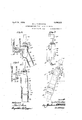
These objects, and other advantageous ends which will be described hereinafter, I attain, in the following manner, reference being had to the accompanying drawings in which Figure 1 is a side elevation of my improved elbow fitting in operative position as above set forth applied to the engine water jacket and adjacent end of the water-circulating pipe of an automobile such for ex ample as an automobile of the well known Ford type, and taking the place of the elbow fitting usually employed,
Figure 2 is a section taken on the line 2-2 of Figure 1 with said pipe removed,
Figure 3 is a section taken on the line 3.3 of Figure 2,
Figure 4 is a section taken on the line ll of Figure 3,
Figure 5 is a front elevation showing my improved elbow tting of a different design from that illustrated in Figures 1 to 4-, inclusive and adapted for example for attachment to the water jacket and adjacent end of the water-circulating pipe of an automobile of the well known Dodge type.
Figure 6 is a sectional elevation taken on the line 6-0 of Figure 5 illustrating the elbow fitting attached to said water jacket and adjacent end oi the waterecirculating pipe.
Figure 7 is an elevation showing my improved elbow fitting made in another form and adapted for use in connection with a water jacket and adjacent end of the watercirculating pipe on an automobile such for GI IZtIIlPlG as an automobile of the well known Overland type.
Figure 8 is a section taken on the line 8-8 of Figure 7.
Figure 9 is an elevation or my improved elbow fitting and of a design adapted for use in connection with the engine water jacket and the adjacent end of a water-circulating pipe of an automobile of the well known Essex type.
Figure 10 is a section taken on the line l0,1 of'Figure 9, showing the fitting attached-to said water jacket and pipe.
Figure 11 is an elevation showing my im- :9we1 elblev page see elated a:
use in connection with the engine water jacket and adjacent end 01 the water-circulating pipe of an automobile of the well known Cadillac type.
Figure 12 is a section taken on the line 1212 of Figure 11 illustrating said elbow fitting attached to said water jacket and cir culating pipe.
Figure 13 is a side elevation of an engine jacket, radiator and water-circulating pipe showing my invention applied thereto.
Referring to the drawings and particularly to Figures 1 to i inclusive, my improved elbow fitting 13 includes an elongated hollow body portion 1 1 which in turn provides an elongated chamber or passage 15 as clearly shown in Figures and 1. The body portion 14 has a hollow extending portion 16 providing a branch chamber or passage 17 which communicates with and forms a part of the chamber 15. This body portion 14 has a laterally extending hollow portion 18 which provides a branch chamber or passage 19 adapted for registry with the intake water opening 20 of the engine water jacket 21. The portion 18 has a projecting flange 22 providing holes 23 through which tap bolts .24 can be inserted for engagement with the tapped. holes 25 in the water jacket 21; said holes 25 usually being employed to secure the usual water intake fitting to the water jacket. The extension 16 is preferably arranged at a slant in alignment with the water-circulating pipe 26 so that when attaching the fitting 13 it is not necessary to change the slant Or angle of the pipe 26 in any manner. This pipe 26 includes a fieXible sleeve or nipple 27 wh ch in the usual Ford construction serves as a means of connection between the metallic portion of the water-circulating pipe and the usual elbow fitting above mentioned and in the present instance this nipple 27 is connected directly to the hollow extending portion 16 and is secured by the clamping band 28. The hollow body portion 14 at its top has an internally screw threaded opening 29 in which is screwed a collar 30 said collar being secured to a heating agent 31 which may be made of the usual hot-point construction; the same including an elongated heating stem 32 which extends lengthwise within the space provided by the chamber 15 so as to be interposed between the branch chambers 17 and 19. The top of the heating agent 31 has an electric conduit-connecting socket 33 which may be of the usual construction and serving to permit an electric conduit to be detachablyconnected thereto.
I preferably attach the collar 30 by first making the same in sections as illustrated, so as to be placed around the stem, of the heating agent, and then solder the parts together and to said stem; said collar serving both to close the opening 29 and to support the heatiiig agent with the heating portion 32 iii the position as above described.
I preferably make the chamber 15 of such cross sectional area that even though the stem oi the heating agent is in position that the space surrounding said portion 32 ot' the heating agent will be sufficient to form a water conduit of a cross sectional area at least as great as the cross sectional area of the pipe 26 so that while there is a heating agent interposed in the chamber between the pipe 26 and the opening 20 of the water jacket the same will not prevent proper and sufiicient supply of water to the water jacket. It will thus be noted that the elbow fitting. 13 can be attached to the water jacket 21 and to the adjacent end of the pipe 26 without in any way altering or changing the positions of the standard parts.
In the form shown in Figures 7 and 8, the principles of construction are substantially the same as that above described with the Xception that the connecting extensionfor the adjacent end oi" the water-circulating pipe is at a different slant, and I have therefore given corresponding parts similar reterence characters.
'The form shown in Figures 5 and 6 permits the attachment of the fitting by the application of a single bolt 24; which extends through the water inlet opening in the water jacket and in this construction instead of providing the flanges 22, a hole 23 is formed through the body portion to allow the insertion of the bolt 2 1. In all other respects the parts are substantially similar to that described in connection with Figures 1 to 4 inclusive and I have therefore given corresponding parts similar reference characters.
The form shown in Figures 9 and 10 is substantially similar to that described in connection with Figures 1 to 1 with the eX- ception that the securing portion has three bolt holes 23 and the extending portion 17 is in-alignment with the body portion and with the exception of the parts noted, I have given corresponding parts in Figures 9 and 10 the same reference characters as applied in Figures 1 to 4 inclusive.
In Figures 11 and 12, I have shown a construction where the elbow fitting has a screw threaded hollow extending portion 18 for engagement witha screw threaded water inlet opening 20 in the water jacket 21 and the same requires no bolts to secure it in position. Otherwise the construction shown in Figures 11 and 12 is substantially similar to that described in connection with Figures 1, 2, 3 and 4; and I have therefore given corresponding parts similar reference characters.-
The body portion and hollow extensions of each of the elbow fittings above described can be inade in the formof a single casting and as obvious from the constructions shown it is an easy matter to connect the same. Furthermore the heating agent is in a position permitting ready access thereto.
In actual use and demonstration in addition to the advantages of connection without change of construct-ion or the cutting away of any parts, I have found that under the most severe tests that by the use of said construction the engine can be kept at the most desirable operating temperature and that the remainder of the water in the circulating system will be kept sufiiciently warm to prevent freezing.
I have also found that by the arrangement above set forth whereby the heat is transmitted directly adjacent the bottom of the base of the water jacket that the greatest efficiency is derived from the heating agent; said heat being of far greater advantage than when applied within the length of the water-circulating pipe or at positions adjacent the radiator.
hile I have described my invention as taking a particular form, it will be understood that the various parts of my invention may be changed without departing from the spirit thereof, and hence I do not limit myself to the precise construction set forth, but consider that I am at liberty to make such changes and alterations as fairly come within the scope of the appended claims.
Having thus described my invention, what I claim as new and desire to-secure by Letters Patent is I 1. An elbow fitting, adapted to be connected with the water jacket of a water cooled engine and with a water circulating pipe, and having, at its end adjacent the water jacket, an enlarged part, and a heater disposed centrally and lengthwise of the enlargement.
2. An elbow fitting, adapted to be connected with the water jacket of a water cooled engine and with a water circulating pipe, and having, at its end adjacent the water jacket, an enlarged part, and a heater detachably secured in the elbow and disposed centrally and lengthwise of the enlargement.
3. An elbow fitting, adapted to be connected with the water jacket of a water cooled engine and with a water circulating pipe, and having, at its end adjacent the water jacket, an enlarged part, and a heater detach ably secured in the upper wall of the elbow and disposed centrally and lengthwise of the enlargement.
4;. An elbow fitting, adapted to be connected with the water jacket of a water cooled engine and with a water circulating pipe, and having, at its end adjacent the water jacket, an enlarged part, and a heater disposed centrally and lengthwise of the enlargement, the cross sectional area of the enlargement being not less than the cross sectional area of the circulating pipe plus the cross sectional area of the heater.
In testimony whereof I have signed my name to this specification in the presence of two subscribing witnesses.
MARTIN C. FURSTENAU.
lVitnesses ELIZABETH GARBE, CHAs. E. Forms.
Priority Applications (1)
| Application Number | Priority Date | Filing Date | Title |
|---|---|---|---|
| US479882A US1490318A (en) | 1921-06-23 | 1921-06-23 | Automobile power-plant protecting device |
Applications Claiming Priority (1)
| Application Number | Priority Date | Filing Date | Title |
|---|---|---|---|
| US479882A US1490318A (en) | 1921-06-23 | 1921-06-23 | Automobile power-plant protecting device |
Publications (1)
| Publication Number | Publication Date |
|---|---|
| US1490318A true US1490318A (en) | 1924-04-15 |
Family
ID=23905827
Family Applications (1)
| Application Number | Title | Priority Date | Filing Date |
|---|---|---|---|
| US479882A Expired - Lifetime US1490318A (en) | 1921-06-23 | 1921-06-23 | Automobile power-plant protecting device |
Country Status (1)
| Country | Link |
|---|---|
| US (1) | US1490318A (en) |
Cited By (2)
| Publication number | Priority date | Publication date | Assignee | Title |
|---|---|---|---|---|
| US2769077A (en) * | 1955-04-22 | 1956-10-30 | James P Calkins | Motor heater |
| FR2722839A1 (en) * | 1994-07-21 | 1996-01-26 | Harang Alain Michel | Pre-heating device for emergency vehicle IC engine to bring it quickly to running temperature |
-
1921
- 1921-06-23 US US479882A patent/US1490318A/en not_active Expired - Lifetime
Cited By (2)
| Publication number | Priority date | Publication date | Assignee | Title |
|---|---|---|---|---|
| US2769077A (en) * | 1955-04-22 | 1956-10-30 | James P Calkins | Motor heater |
| FR2722839A1 (en) * | 1994-07-21 | 1996-01-26 | Harang Alain Michel | Pre-heating device for emergency vehicle IC engine to bring it quickly to running temperature |
Similar Documents
| Publication | Publication Date | Title |
|---|---|---|
| US1490318A (en) | Automobile power-plant protecting device | |
| US2258526A (en) | Engine cooling system | |
| US2708824A (en) | Water cooled exhaust elbow | |
| US2211831A (en) | Automobile heating apparatus | |
| US1338938A (en) | Auxiliary device for gas-engines | |
| US1444133A (en) | Thermometer attachment for automobiles | |
| US2137231A (en) | Thawing attachment for the hose connections and radiator of an internal combustion engine | |
| US1271135A (en) | Radiator. | |
| US932113A (en) | Foot-warming radiator for automobiles. | |
| US1833068A (en) | Fluid control valve | |
| US1431212A (en) | Means for introducing temperature-responsive elements into engine cooling systems | |
| US1315423A (en) | sapper | |
| US1658575A (en) | Water-hose connection | |
| US1849934A (en) | Automotive heater | |
| US2492001A (en) | Engine block electric-type water heater | |
| US1110606A (en) | Water-circulating means for internal-combustion engines. | |
| US1629101A (en) | Oil heater for crank cases | |
| US1772341A (en) | Automobile heating system | |
| US1974639A (en) | Valve for an automobile heater | |
| US1394025A (en) | Automobile water-pump | |
| US1117354A (en) | Gasifying device for liquid fuel. | |
| US1550947A (en) | Internal-combustion engine | |
| US1501065A (en) | Cooling system | |
| US1285711A (en) | Cooling system for internal-combustion engines. | |
| US3071186A (en) | Mounting bracket for heat exchangers and the like |