US1480098A - Molding machine - Google Patents
Molding machine Download PDFInfo
- Publication number
- US1480098A US1480098A US575487A US57548722A US1480098A US 1480098 A US1480098 A US 1480098A US 575487 A US575487 A US 575487A US 57548722 A US57548722 A US 57548722A US 1480098 A US1480098 A US 1480098A
- Authority
- US
- United States
- Prior art keywords
- plates
- sets
- crank arms
- molding machine
- crank
- Prior art date
- Legal status (The legal status is an assumption and is not a legal conclusion. Google has not performed a legal analysis and makes no representation as to the accuracy of the status listed.)
- Expired - Lifetime
Links
Images
Classifications
-
- E—FIXED CONSTRUCTIONS
- E04—BUILDING
- E04G—SCAFFOLDING; FORMS; SHUTTERING; BUILDING IMPLEMENTS OR AIDS, OR THEIR USE; HANDLING BUILDING MATERIALS ON THE SITE; REPAIRING, BREAKING-UP OR OTHER WORK ON EXISTING BUILDINGS
- E04G11/00—Forms, shutterings, or falsework for making walls, floors, ceilings, or roofs
- E04G11/06—Forms, shutterings, or falsework for making walls, floors, ceilings, or roofs for walls, e.g. curved end panels for wall shutterings; filler elements for wall shutterings; shutterings for vertical ducts
- E04G11/08—Forms, which are completely dismantled after setting of the concrete and re-built for next pouring
- E04G11/18—Forms, which are completely dismantled after setting of the concrete and re-built for next pouring for double walls
Definitions
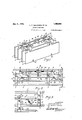
- Figure l is a perspective View of a straight wall molding machine.
- Figure 2 is aconventional plan view ot Figure 1,,i a clOsed position, and partly in profile to illustrate the same in an open po siti0n.
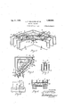
- Figure ⁇ is a part plan view of the same space therebetween, and also in profilefor for another size double- Figure 4 is a perspective'view of an angular double-wall molding machine.
- Figure 5 is a conventionalplan View of Figure 4. a y a.
- clamps, 22 are tolthellshafts 13',"an d arejoperatively positioned between the said plates 3 and l in thetwojends thereof, the
- cranks are in turn adjustably secured to the top :poiitions of; 1 the said shafts 13, and i allow.
- the said clamps 221:0 stand atany de sired: angle, depending upon the distance lying between the said plates 3 and .4, the i said cranks 24: extend operatively over the top fates of the said bars.
- Gland; 8', and the pins 11 andfl12 are in turn connected to 'the positioned in anotherai'm on the said cranks 'two arms oflthe cranks; 24c, and 'to i the. bars n 8 ,andffi respectively, the jointsil l are in turn:
- the"bars 27 are "first, placed on, or into,the foundation walls'upon which'the double wall is to be” built, the 'moliding'ma chineis then set into an open position as hereinafter described, and is 'plaiced'over the said walls to allow the plates 3 andj l to rest onthe bars 27', or on a flat foundation, the
- the cranks 24 may be formed to project the'pins ll and 12 at angular positions from the shafts 13, so as to throw the said pins 11 and'12 aroundtheshafts 13, as the moldingmachine is opened, to allow the plates 1-4; and 372 to move "away from an end ob-' struction, as shown ,in' profile and arrow points in Figure '2.
- crank means operatively positioned betweenthe said hold ing means for the two sets of plates, adapted to open'andr close the said sets of plates, crank arms. integral with-:the said crank central portion of the said separating means,
- a separating means adapted to con trol the space between the said pair of crank ,means, a supporting arm-integral with the central portion of the ,sai'ds'eparafl ing means, an adjustment-means,adapted'to be connected to the said crank arms and supporting arm, an operating means, and a clamping means, adapted to hold the said molding machine in a. closed position.
- intermeshed plates intermeshed plates, an adjustable support- .ing means for each set of plates, a set of.
- crank arms operatively positioned between the said adjustable supporting means, adapted to open and close the said sets of plates radially in relation to their centers, an adjustable operating means positioned between the said crank arms, a spacer means connected to the center portion of the said crank arms, a supporting arm secured to the said spacer means, adapted to receive the said adjustable operating means, a clamping means, adapted to hold the said sets of plates in their stationary positions, as set forth.
- A. molding machine of the class described the combination of two sets of intermeshed plates, a supporting means secured to the end portions of each set of plates, adapted to adjust the spaces therebetween, crank arms. operatively positioned between the said supporting means, adapted “to shift the said sets of plates radially in relation to their centers, auxiliary crank arms securedto the said crank arms, an operating means positioned between the said auxiliary crank arms, adapted to open and close the said sets of intermeshed plates, a spacer means connected to the center portion of the said crank arms, a supporting.
- clamping means adapted to hold the said i sets of intermeshed plates intheir stationary positions, a holding means secured to the lower-center portion ofthe said crank arms,
- a molding machine of the class deto the end portions of each set of plates, adapted to adjust the spaces therebetween, crank arms operatively positioned between the said supporting means,adap ted toshift the said sets of plates radially in relation to their centers auxiliary crank arms secured to the said crank arms, anoperating means positioned between the said auxiliary crank arms, adapted to open and close the said sets of intermeshed plates, a spacer means connected to the center portion of the said crank arms, a supportingarm secured to the said spacer means, adapted to receive the said operating means, a clamping means, adapted to hold the said sets of in- 'termeshed plates'in their stationary positions, a'holding means secured to the lower center portion of the sald crank arms,
Landscapes
- Engineering & Computer Science (AREA)
- Architecture (AREA)
- Mechanical Engineering (AREA)
- Civil Engineering (AREA)
- Structural Engineering (AREA)
- Blow-Moulding Or Thermoforming Of Plastics Or The Like (AREA)
Description
Jan. 8' 1924, 1,480,098
' L. F. MULQUEEN'ET AL MOLDING MACHINE Filed July 17 1922, 2 sheets-sn ak 1 INVENTORS. 4 50 f7 MUL QUEEN A/vo eqm/cx WMSH,
ATTORNEY.
To azzaho amay aa'm- Patented J an. 8, 1924. i
v 1,4s,09s UNITED," SIATESSTPATENT OFFICE;
LEO F. MULQUEEN Ann PATRICK wALsH; oF Los NoELEs, CALIFQBNIAY 1 Application filed my 17',
Be it known that weQLEO F. MUL UnnN and PATRICK WALSH, citizensof the United States, residing at Los 'Angles, in the county of Los Angelesand State of California,;have invented certain new and iusefulllmprove ments in Molding 'Maehines;., of which the following isaspejcification' p i q This invention rel tes toniolding'jma-l chines and more particularly tothe type em ployed for molding concrete orsimilarplastic material. p k i It has for an object to provide a construe-e tiOn j which rnay be utilized for directly building solid or hollow Walls from con-. crete.
Tothese and other ends theinvention consi ts of eertain partsland combination of parts to be hereinafter more particularly demaohine, set for one size double-wall and air another adjustment wall and air space.
scribed, the novel features thereoffbeing pointed out in the appended claims. a In the drawings Figure l is a perspective View of a straight wall molding machine.
Figure 2 is aconventional plan view ot Figure 1,,i a clOsed position, and partly in profile to illustrate the same in an open po siti0n. I a
Figure} is a part plan view of the same space therebetween, and also in profilefor for another size double- Figure 4 is a perspective'view of an angular double-wall molding machine.
Figure 5 is a conventionalplan View of Figure 4. a y a. Figure Sis a sectionalviewon line 66 of Figure 8. v
Figur ,7 is of Figure 5. i i i i a Figure 8 is a part side view of Figures 1 and Q, disclosing an arrangement for? hold ing the onter plates in a closed position. v i In theembodiment of the invention herein illustrated, the molding' machine comasectional view on line 7,7
prises two pairs of plates land 2, and S and l respectivelmto form thei -outer and inner Walls thereof, the bars 8-7 and,65 .are, made integral Withthe ends of the top portionsof the said'plates'23and l1 respe a tively. and the? joining portions positioned between the said bars 5+6 and 7"8 are in turnbent together the slots 30 and 3lpass:
thru the bars 5*6 and -7 8 respectivelmand thepins 9+10 in turn passthrulthe said slots.
1 30e-3l respectivelyjasshown inFigureii. The
clamps, 22 are tolthellshafts 13',"an d arejoperatively positioned between the said plates 3 and l in thetwojends thereof, the
cranks are in turn adjustably secured to the top :poiitions of; 1 the said shafts 13, and i allow. the said clamps 221:0 stand atany de sired: angle, depending upon the distance lying between the said plates 3 and .4, the i said cranks 24: extend operatively over the top fates of the said bars. Gland; 8', and the pins 11 andfl12 are in turn connected to 'the positioned in anotherai'm on the said cranks 'two arms oflthe cranks; 24c, and 'to i the. bars n 8 ,andffi respectively, the jointsil l are in turn:
Ma h point lyingflopposite the said shafts connected tol the said jointsll and shafts 13 respectively, andflare positioned between the 13, on a line drawnibetwe'en the saidipins ll and 12,.the links 15,and- 16 ane operatively into the an ,p'omjbn of "the man; andthe nut 191s 'in' turn slidably shouldered into the it said slot 18, the threads [20 are cut inthe central portion of; the link 1 5 and carries .T e platesfll are operatively connected to th esaid 1111519, the lock nut29 is also carried Ion j the threads 20iifia point lying adjag 1 cent to the said nnt'l9j thetop edgesiof thefplates 3 andlc, as shown inFigure :7,;jand extend the, full length of the'said plates 3 and ethe said plates 21 also liepperatively beneath the bars 5 and 7 and I the cranlis 2 L respectively, and pass I operatively aroundfthe shafts 13, and open atively overlap (one! another at their joining edgesinasalso shown in Figure; 7.
machine is raisedtoits next higher elevation andthepwires 26.. are also employedito secure theplates-l and 2 inpftheir closed posi tions as hereinafter described Several sets ofslots 25pass up thru the bottomedges of the plates 1, 3, 4:4 and 2; irespeotively in straightlines-withconeanother, as shown in Figures 6 and 8, the said: slotsv 25 are ta peredtopoints-at theinner end portions thereof, the said wires 26, are in turn forced a into the pointed portions" ofthesaid slots 25,. and extendthrulthe platesl -3, and e se shown in, Figureifi, and the end, portions I of v in'gi'the plates 3"-2 andi'thei'r] supporting the said wires 26 arein' turn'bent:around the? V slots 30,.31,-,32 and 33, the bar 6 may then,
be 'm'oved 'overthe bar obtain'the -re quire'd space between the platesaa and 2', and the bar '8 may in 'turn"be'moved'overthe bar 7 to obtain'the"requiredfspace between the plates 1 and 3,"the ,barsf65 andi'8'7 are?" then secured'together by'clainpingthe said pins 9 and 10in their respectivesl'ots" and 31 ,the required Width'of airspace between the plates 3 and 4 'isin turn derived'by shift bars6-5 as a unit," and alsothle plates 1-1 and'their supportin bars 8j7 as a unit, the pins'll and 12 are" thenclamped :in their respective slots 32 and 33' to holdthe cranks 24, shafts 13 and clamps'22' in position in 're-] lationito thesaid airspace;
To operate the molding machine after the sameha's been. adjusted as hereinbeforede'-' scribed,"the"bars 27 are "first, placed on, or into,the foundation walls'upon which'the double wall is to be" built, the 'moliding'ma chineis then set into an open position as hereinafter described, and is 'plaiced'over the said walls to allow the plates 3 andj l to rest onthe bars 27', or on a flat foundation, the
::r moldingmachine is then'closed to bring the plates '1,3,4 and 2 flush with the respective i faces of the'said supporting double wall, and W the wires 26 are then driveninto the several sets of slots 25",and'are bent over the" outerv faces of the said plates 1 and2to preventlthe when concrete, or other plastic materials are tamped therebetween, or between the plates, 1-3, or 4-2 respectively;
To open the.m0lding machine as shown" in Figures 2 and 5,'-it willbeseen' that the nut ,19 slidably inthe slot l8, on the threads. 20, andjto closethe same, the1link15 'is' again" moved in the opposite direction. as hereinbe' their top ends to, suit the width'of thespace; lyin T eplat'es2- 21 m'ayf beusedfto close the air space lying between the plates 3 and 4,120
prevente'th'e concrete or 'other iplastic materials from falling into the "same when being poured into the spaces lying between the p1ates11-j3, and
The cranks 24 may be formed to project the'pins ll and 12 at angular positions from the shafts 13, so as to throw the said pins 11 and'12 aroundtheshafts 13, as the moldingmachine is opened, to allow the plates 1-4; and 372 to move "away from an end ob-' struction, as shown ,in' profile and arrow points in Figure '2.
Hat ing'thus decribed our invention what we claim is'i 1. In ay'machine *of the class described,
'betweenthe-said respectivesets of plates and individual plates, a pair of crank means operatively positioned betweenthe said hold ing means for the two sets of plates, adapted to open'andr close the said sets of plates, crank arms. integral with-:the said crank central portion of the said separating means,
as set'forth." 7
2. In a molding m'achlne'comprismg two tween one another, in combination with a holding means for the: onepair of plates, and ayholdingg means'fortheother pair of comprising 2 sets ofm'olding'plates, the "sec- 'means-,"a separatingmeans, adapted to conpair of plates, the saidvtwopair 'of' plates are adaptedtobe alternately positioned beplates, a pair of "crank means operatively positioned between the said" holding means lower edges thereof from spreading"aparti1 for the two pair ofplates, adapted to'open and close thesa-id pair of pl,ates,crank arms integral with'the said crank means,- a separating means, adaptedtocontrol the space between the said pair of crank means, a supporting arm integral-with'the" central porlink 16 remains in a stationary position, and the link 15 is 'm'ovedin the directionlshown by the arrow point thereomfby turningithef tion of the said separating means, a regulating means, adapted toadjus't' the spacesyly lli) ing between the saidtwo pair of plates, as
set forth.
a Iiiusin machine of the as described,- in combination with two sets of 5 i plates, adapted toopen and: close in unison with one another, a supporting means, adapted to hold the saidplates in their re-" spective sets, a pair of'crankmeansoperatively positioned betwe'en' thesaid ho1ding means for the two pair} of platesyadapt ed to open and close thesaid' sets of plates, crank arms integral with'tthe said crank means. a separating means; adapted to con trol the space between the said pair of crank ,means, a supporting arm-integral with the central portion of the ,sai'ds'eparafl ing means, an adjustment-means,adapted'to be connected to the said crank arms and supporting arm, an operating means, and a clamping means, adapted to hold the said molding machine in a. closed position.
4. In a molding machine of the class described, in combination with several sets of plates, adapted to open and close in unison .with one another, a supporting means for.
intermeshed plates, an adjustable support- .ing means for each set of plates, a set of.
crank arms operatively positioned between the said adjustable supporting means, adapted to open and close the said sets of plates radially in relation to their centers, an adjustable operating means positioned between the said crank arms, a spacer means connected to the center portion of the said crank arms, a supporting arm secured to the said spacer means, adapted to receive the said adjustable operating means, a clamping means, adapted to hold the said sets of plates in their stationary positions, as set forth.
6. A. molding machine of the class described, the combination of two sets of intermeshed plates, a supporting means secured to the end portions of each set of plates, adapted to adjust the spaces therebetween, crank arms. operatively positioned between the said supporting means, adapted "to shift the said sets of plates radially in relation to their centers, auxiliary crank arms securedto the said crank arms, an operating means positioned between the said auxiliary crank arms, adapted to open and close the said sets of intermeshed plates, a spacer means connected to the center portion of the said crank arms, a supporting.
arm secured to the said spacer means, adapted to receive the said operating means, a
clamping means, adapted to hold the said i sets of intermeshed plates intheir stationary positions, a holding means secured to the lower-center portion ofthe said crank arms,
adapted to extend operatively between the two central plates on the said sets of intermeshed plates, as set forth.
7. A molding machine of the class deto the end portions of each set of plates, adapted to adjust the spaces therebetween, crank arms operatively positioned between the said supporting means,adap ted toshift the said sets of plates radially in relation to their centers auxiliary crank arms secured to the said crank arms, anoperating means positioned between the said auxiliary crank arms, adapted to open and close the said sets of intermeshed plates, a spacer means connected to the center portion of the said crank arms, a supportingarm secured to the said spacer means, adapted to receive the said operating means, a clamping means, adapted to hold the said sets of in- 'termeshed plates'in their stationary positions, a'holding means secured to the lower center portion of the sald crank arms,
adapted to extend operatively between the two central plates on the said sets of intermeshedplates self releasing support wires,
adapted to hold the lower portion of the said plates in a locked position, a set of. bars, adapted to support the said molding machine, as set forth. 1
In testimony whereof we aiiixiour signaturesv LEO n. MULQUEEN. PATRICK WALSHgf 60 I scribed, the combination of two sets of intermeshed plates, a supporting means secured
Priority Applications (1)
| Application Number | Priority Date | Filing Date | Title |
|---|---|---|---|
| US575487A US1480098A (en) | 1922-07-17 | 1922-07-17 | Molding machine |
Applications Claiming Priority (1)
| Application Number | Priority Date | Filing Date | Title |
|---|---|---|---|
| US575487A US1480098A (en) | 1922-07-17 | 1922-07-17 | Molding machine |
Publications (1)
| Publication Number | Publication Date |
|---|---|
| US1480098A true US1480098A (en) | 1924-01-08 |
Family
ID=24300518
Family Applications (1)
| Application Number | Title | Priority Date | Filing Date |
|---|---|---|---|
| US575487A Expired - Lifetime US1480098A (en) | 1922-07-17 | 1922-07-17 | Molding machine |
Country Status (1)
| Country | Link |
|---|---|
| US (1) | US1480098A (en) |
Cited By (1)
| Publication number | Priority date | Publication date | Assignee | Title |
|---|---|---|---|---|
| CN108625589A (en) * | 2017-03-24 | 2018-10-09 | 中国二十冶集团有限公司 | The mutual support shaped steel mould method for supporting of shear force wall deformation slit |
-
1922
- 1922-07-17 US US575487A patent/US1480098A/en not_active Expired - Lifetime
Cited By (2)
| Publication number | Priority date | Publication date | Assignee | Title |
|---|---|---|---|---|
| CN108625589A (en) * | 2017-03-24 | 2018-10-09 | 中国二十冶集团有限公司 | The mutual support shaped steel mould method for supporting of shear force wall deformation slit |
| CN108625589B (en) * | 2017-03-24 | 2021-01-19 | 中国二十冶集团有限公司 | Supporting method of inter-supported steel formwork for deformation joints of shear walls |
Similar Documents
| Publication | Publication Date | Title |
|---|---|---|
| US1480098A (en) | Molding machine | |
| US812336A (en) | Machine for forming concrete blocks. | |
| US2505467A (en) | Gate having multiple pintle spring hinge means | |
| US1272281A (en) | Cement-form tie-clamp. | |
| US3673930A (en) | Screed extension assembly for asphalt paving machines | |
| US1986090A (en) | Coiling block | |
| US859681A (en) | Culvert-mold. | |
| US3677512A (en) | Pre-fab form for concrete | |
| US1670338A (en) | Column form | |
| US1126355A (en) | Concrete pipe and mold. | |
| US1947625A (en) | Collapsible form for concrete constructions | |
| US1453174A (en) | Concrete form | |
| US500443A (en) | Dehorning implement | |
| US2765689A (en) | Parallel jaw pliers | |
| US1208281A (en) | Mold. | |
| US1825865A (en) | Expansion mandrel | |
| US1055862A (en) | Collapsible form for building culverts. | |
| US1350994A (en) | Stump-puller | |
| US1374199A (en) | Concrete-mold | |
| US1414287A (en) | Form for concrete walls | |
| US1057550A (en) | Concrete-block-molding machine. | |
| US1331630A (en) | Die for spring-forming machines | |
| US1172423A (en) | Adjustable head-gate. | |
| US1631838A (en) | Collapsible core | |
| US837328A (en) | Culvert-mold. |