US1479984A - Telephone-exchange system - Google Patents
Telephone-exchange system Download PDFInfo
- Publication number
- US1479984A US1479984A US478894A US47889421A US1479984A US 1479984 A US1479984 A US 1479984A US 478894 A US478894 A US 478894A US 47889421 A US47889421 A US 47889421A US 1479984 A US1479984 A US 1479984A
- Authority
- US
- United States
- Prior art keywords
- contact
- sequence switch
- relay
- circuit
- ground
- Prior art date
- Legal status (The legal status is an assumption and is not a legal conclusion. Google has not performed a legal analysis and makes no representation as to the accuracy of the status listed.)
- Expired - Lifetime
Links
- 238000004804 winding Methods 0.000 description 30
- 230000007246 mechanism Effects 0.000 description 16
- 238000012360 testing method Methods 0.000 description 11
- 238000012544 monitoring process Methods 0.000 description 5
- 230000000694 effects Effects 0.000 description 2
- IJJWOSAXNHWBPR-HUBLWGQQSA-N 5-[(3as,4s,6ar)-2-oxo-1,3,3a,4,6,6a-hexahydrothieno[3,4-d]imidazol-4-yl]-n-(6-hydrazinyl-6-oxohexyl)pentanamide Chemical compound N1C(=O)N[C@@H]2[C@H](CCCCC(=O)NCCCCCC(=O)NN)SC[C@@H]21 IJJWOSAXNHWBPR-HUBLWGQQSA-N 0.000 description 1
- 244000105975 Antidesma platyphyllum Species 0.000 description 1
- 230000005540 biological transmission Effects 0.000 description 1
- 230000008859 change Effects 0.000 description 1
- 238000010276 construction Methods 0.000 description 1
- 230000001419 dependent effect Effects 0.000 description 1
- 238000007429 general method Methods 0.000 description 1
- 235000009424 haa Nutrition 0.000 description 1
- 238000012986 modification Methods 0.000 description 1
- 230000004048 modification Effects 0.000 description 1
- 230000002028 premature Effects 0.000 description 1
- BALXUFOVQVENIU-KXNXZCPBSA-N pseudoephedrine hydrochloride Chemical compound [H+].[Cl-].CN[C@@H](C)[C@@H](O)C1=CC=CC=C1 BALXUFOVQVENIU-KXNXZCPBSA-N 0.000 description 1
- 230000004044 response Effects 0.000 description 1
Images


Classifications
-
- H—ELECTRICITY
- H04—ELECTRIC COMMUNICATION TECHNIQUE
- H04Q—SELECTING
- H04Q3/00—Selecting arrangements
Definitions
- This invention relates to telephone exlfl change systems and particularly to those in which machine switching apparatus is employed tor the establishment of talking connections between calling and called subscribers lines.
- the automatic selective switches used for extending talking connections toward the called lines are arranged to be controlled from the central oitice, it is customary to provide controlling senders of the LU register type.
- a plurality of these senders are located at the central oiiice and receive on their registers the digital records of the called lines. These records may be set up on the controlling registers either by means 5 of an operators keyboard or by means of impulses transmitted over the calling line from the subscribers substations, according as the system is semi-automatic or full automatic in character.
- The' sender after tak- 30 ing its setting operates to determine the selfi lective movements of the several switches inthe extension of the desired connection.
- cord linder mechanisms are provided for the attachment of the senders to the proper cord. These finder mechanisms are operated automatically in response to the extension of a calling line to any cord in the group they serve and, upon finding the particular cord 15 concerned, associate an idle register mechanism therewith.
- the object of the present invention is the provision oi a cord iinding mechanism consisting of a plurality of separate switching 5i) devices, each having access to all co-rds in a group, and acting jointly to attach a register sender to any cord.
- ⁇ A. feature of the invention relates to the provision of a cord iinder consisting of two switches, one of which is ⁇ operated to'extend an impulse circuit from any co-rd to a register sender for causing the designation to ⁇ be recorded on the register, andthe other of which operates to complete a controlling circuit from the sender tothe saine cord, whereby the record established on'the sender determines the selective operation of the automatic switches.
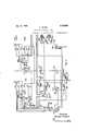
- Figs. 1 to 6 disclose parts of a telephone ⁇ exchange system wherein the features of the invention are embodied. 'The sheets of the drawing Should be arranged with Fig. 2 below Fig. 1, Fig. 4 tothe right of Fig. 1,"and Fig. ⁇ 3 to the right of Fig. 2. i
- Fig. 1 shows a subscribers line.- and a first line finder switch, diagrammatically ⁇ illustrated, for extending such line tothe terminals of a second line finder. This figure also showsdetailed circuits of the second line linder switch and a first group selector switch.
- Fig. 2 illustrates the two separate switches of the cord linding mechanism which have access to a'plurality of cord circuits.such as the one interconnecting the brushes of the second line iinder and the first group selector shown in Fig. 1.
- Fig 3 shows the registers of the sender controlling mechanism.
- Fig. 4 illustrates a second group selector switch to which connections are extended from the first group selector shown in Fig. 1.
- Fig. 5 illustrates, diagrammatically, a selector switch having access to the terminals of trunks which lead to anv operators position together with a portion of the cordvcircuit at such position.
- Fig. 6 shows a modification of the answeri'ng plug of the operators cord circuit.
- the selective switches shown in Figs. 1 and 4 and the two cord finder switches 201 and 202, disclosed in Fig. 2, are of the rotary power driven type, the construction and operation of which are described in detail in the atent to McBerty, No. 1,097,868, issued l ay 26, 1914.
- sequence switch contacts to the left of the vertical broken line in Fig. 1 are part of timing sequence switch 100, and those to the right of this line are controlled by the sequence switch 130. All of the sequence switch contacts in Fig. 2 belong to the sequence switch 230. Likewise vall of the sequence switch contacts in Fig. 4 are a part of the sequence switch 420. In Fig. 3 all contacts above the horizontal broken line are controlled by the sequence switch 350, while all contacts located within the broken rectangles at the bottom of the ⁇ ligure are controlled respectively bythe registers 340, 330, 320, 310, and 300, correspondingly located.
- l/Vhile sequence switch 130 is passing position 3 and is in position 4, the common starting circuit for the registers, Figs. 2 and 3, is closed from ground, right-hand back contact of relay 158, sequence switch contact 146 bottom, back contact of relay 143, relay 205 of each idle register circuit andl contact 239 of register sequence switch 230.
- a test potential is placed on the terminals 218 of the finders 201.
- Each connection circuit is wired to a set of contacts on two associated finders, finder 201 and finder 202.
- a group of registers have, therefore, access to all connection or cord circuits which may be connected to their arc terminals.
- the energization of the starting relay 205 closes at its left-hand contact a circuit over sequence switch contact 262 bottom and back contact of relay 213 for the energization of power magnet 210 and the brush carriage of the finder 201 searches for the terminals of the cord circuit.
- a circuit is established from battery, relay 143, sequence switch contact 144 bottom, terminal 218, high resistance winding of relay 215 and sequence switch contact 264 of sequence switch 230 to ground.
- rFest relay 215 operates and makes the cord circuit busy to all other finders similar to finder 201 by shunting its high resistance winding by its low resistance winding ⁇ over its front contact to interrupter 212.
- test relay 213 When the brushes center themselves, the ground at the interrupter is removed and test relay 213 is operated. At its back contact relay 213 opens the circuit of power i magnet 210 and at its front contact closes a circuit from ground, left-hand front coni tact .of relay 205. sequence switch contact 262 for the energization of holding magnet 211 and in parallel therewith closes a circuit over sequence switch contact 236 bottom for register sequence switch 230 which advances to position 4. 1When sequence switch 230 is passing positions 2 and 3 and is in position 4, relay 253 is energized in a circuit from right-hand back contact of relay 247 and over sequence switch contact 251 left. Relay 253 connects the stepping ⁇ relay 243 to the connection circuit by way of the brushes 216 and 217.
- relay 253 having been energized as eX- plained
- relay 243 is energized in a circuit from ground, one winding of relay 243, one winding of dialing tone coil 248, outer front Y contact of relay 253, brush 216, sequence switch contact 106 of sequence switch 100, upper back contact of relay 160, brush 152 ol.l the second line finder and thence through the telephonev circuit and dial contacts over the other side of the line to brush 153 of the second line iinder, lower back contact of relay 160, brush 217, inner front contact of relay 253, other winding of dialingr tone coil 248, other winding of relay 243 to battery.
- the corresponding finder 202 automatically ifollows.
- the circuit of power magnet 220 is closed from ground, right-hand iront contact ot relay 205, back contact of relay 225, the second winding of relay 205, power magnet 220 to battery.
- the brushes ot' iinder 202 come in contact with the terminals 226 to 229, corresponding to the terminals 216 to 219, selected by linder 201, a circuit is established from battery, over terminal 219, terminal 229 to ground at interrupter 222.
- the brushes of finder 202 center themselves this ground is removed and the circuit continues to ground through relay 225 and the right-hand front Contact ot relay 205.
- litelay 225 operates and causes the energization of holding magnet 221 and the deenergization of power magnet 220 and of relay 205.
- the finders 201 and 202 will always come to rest on corresponding terminals. Should, however, one of these finders be moved by hand or otherwise, while idle, it is possible that the finder 201 may select the cord circuit some time in advance of the finder 202, in which case, sequence switch 230 may be stepped out of position 2 and the common starting circuit for the register be opened at sequence switch contact Relay 205, remains energized, however, by virtue of its second winding until the nder 202 reaches the proper terminals. Should the finder 201 be in contact with the terminals of the cord circuit at the moment lthe common starting circuit is i.
- sequence switch 130 When sequence switch 130 reaches .position 4, the combined timed metering and monitoring sequence switch 100 is energized in a circuit. from ground, back Contact ot relay 163, contact 149 bottom oi sequence switch 130 and contact 108 top of sequence switch 100. Sequence switch 100 advances to position 6 andthen to positionl 7 by means of a circuit from ground, contact 145 top out sequence switch 130 and contact 107 bottom of sequence switch 100. j Premature release- 1li the calling subscriber fails to dialwithin a predetermined time, or in the case of a false call, i.. e., a call due to a ground, crossed wires, or the like, sequence switch 130 ot the cord circuit and sequence switch 230 ofthe register circuit will remain in position 4.
- Sequence switch 100 being inposition 7, as above described, the constantly ⁇ rotating interrupter 114 alternately closes and opens, for equal periods, a circuit from ground, interrupter 114, contact 135 bottom ot sequence switch 130, timing sequence switch contact 104 and relay .136 to battery.
- relay 136 energizes and closes a circuit at Contact 102 top for moving sequence switch 100 into position 8.
- 1i/Vheninterrupter 114 opens this circuit, relay 136 is released and at its back contactcloses a circuit over contact 102 bottom ot sequence switch 100 for the energization ot sequence switch 100 which advances to position 9.
- sequence switch 100 reaches position 12, 'from which position it advances to position 13 by means of a circuit. from ground Contact 145 top ol' sequence switch 130 and contact 107 bottom of sequence switch 100. From this point sequence switch 100 continues under the control ot interrupter 114 asabove describeduntil it has advanced into position 17. ⁇ The exact time required to step sequence switch 100 from position 7 to position 17 will, of course, depend upon the positionot interrupter 114 at the moment when the circuit of relay 136 is closed at Contact 135 bottom. f
- sequence switch 100 When sequence switch 100 reaches position 17, the circuit of stepping relay243 is opened at contact 106 .ot' sequence switch 100.
- Relay 243 deenergizes and causes the energization of relay 240 in positions 4, 6, 8, 11 and 13 of sequence switch 230.
- the energization of relay 240 causes the energization of relay 237. In each ot these positions a circuit is established from ground, front loo iso
- sequence switch 230 is advanced from position 4 to position 15, in which position a circuit is closed from ground, contact 366 of sequence switch 350, and contact 236 of sequence switch 230 for the energizat-ion of sequence switch 230, which moves into position 1. As ⁇ sequence switch 230 leaves position 15, relay 253 is released.
- sequence switch 230 In positions 5 and 6 of sequence switch 230, -a circuit is established from ground, right-hand back contact of relay 247, sequence switch contact 232 top and contact 353 top for the energization of sequence switch 350, which advances to position 3. In this position it is again energized in a circuit from ground, back contact of relay 373, sequence switch contact 374, contact 256 of 'sequence switch 230, one winding and back contact of relay 378, (also in parallel through the other windingv of this relay) sequence switch contact 364, contact 342 top of register 340, and sequence switch contact 365, and advances to position 4.
- sequence switch 350 is energized in a circuit including its'contact 353 and contact 232 of sequence 'switch 230, in positions 7 to 13, and advances to position 5.
- position 5 of sequence switch 3-50 a circuit is established from battery to the winding of said sequence switch, lower contact 365, contact 342 of register 340, lower contact 364, contact 334 of register 330, upper contact 362, contact and armature yand righthand winding of relay 378, contact 256,
- Sequence switch 350 advances from position 5 into position 7. A circuit is then established from ground, contact 233 of sequence switch 230 and sequence switch Contact 353 top oi sequence switch 350; sequence switch 350 moves into position 9, in which its energizing circuit is closed as in position 3, except that instead of passing through sequence switch contact 364 top, etc., it passes through sequence switch contact 399, register contact 323 top, sequence 'switch contact 362, register contact 334, sequence switch contact 364 bottom, register contact 342, and sequence switch contact 365. Sequence switch 350 goes to position 10 in which its circuit is' closed over its contact 353 and contact 233 of sequence switch 230, or over its contact 365 top and contact 233 of sequence switch 230.
- sequence switch 350 In position 11 of sequence switch 350 its energizing circuit is closed over sequence switch contact 354, register contact 318, sequence switch contact 356 and thence over the back contact and winding of relay 378, contact 256, upper contact 374 to ground 'at the armature of relay 37 3, or over contact 251 of vsequence switch 230 and back Contact of relay 247
- the circuit In position 12, the circuit is over sequence switch contact 365 top and contact 233 of sequence switch 230; in position 14, over sequence switch contacts 354, register contact 304, back contact of relay 355, register contact 302, sequence switch contact 356 bottom, and back contact of relay 378, etc., or contact 233 of sequence switch 230; in position 16, the same as for position 9; in position 17, the same as for position 11; in position 18, the same as for position 11.
- Sequence switch 350 therefore returns to normal position.
- sequence switch 350 passes position 2
- a circuit is momentarily closed from ground, sequence switch contact 375, brush and terminal ⁇ 228, and contact 137 or sequence switch 130, sequence switch 130 to battery.
- Sequence switch 130 moves into position 5, in which position-the circuit of relay 136 is opened at sequence switch contact 135 bottoni.
- sequence switch 1,00 is advanced to position 18, the energizing circuit extending from ground over sequence switch contact 145 bottoni and sequence switch contact 108 bottom.
- the circuit of the monitoring lamp A119 is closed from ground, sequence switch contact 145 bottom, timing sequence switch contact 109, holding key 115, lamp 119 to battery.
- Sequence switch 130 remains in position 5 and sequence 'switch 100 in position 18 until they are released by the subscriber or operator. lhen the register circuit is released, a shortcircuit around relay 150 through brush and terminal 218 is removed and relay 150 becomes reenergized in a circuit from ground', winding of relay 150, resistance 157, sequence switch contact 144 top, winding of marginal relay 143 to battery; relays 160, 161 and 164 arethe-retore also reenergized.
- the subscriber may release switches 100 and 130 at any time by hanging up his receiver, thereby closing a circuit from ground, lront contact of relay 161, back contact et relay 162, sequence switch contact 159 top, release relay 158,l holding ley 115 to battery.
- Release relay 158 is energized and locks up over its left-hand front contact and sequence switch Contact 155 bottom, and freeing the calling subscribers line by opening at its left-hand back contact the circuit of the wire to terminal ⁇ 154.
- At its right-hand 'front contact relay 158 closes an energizing circuit over sequence switch contact 132 top ior sequence switch 130 which is returned to normal.
- Sequence switch 130 passes positions 8 and 16 since relay 141 is energized in these positions over the home contact ot interrupter 156, sequence switch contact 138 and magnet 171 to battery; the circuit ior sequence switch 130 is closed in these positions trom ground, sequence switch contact 142 bottom, front contact of relay 141 and sequence switch contact 140 top.
- the operator upon noting the4 burning of monitoring lamp 119 may throw holding key 115. This transfers the circuit oit the monitoring lamp to the back contact oit the calling supervisory relay 162 and opens the circuit of the release relay 158, so that should the line become free the lamp will again burn Abut the connection circuit will not he released. Vfhile the connection cir cuit is thus held, the operator may malte connection through the ley 113 and apply the usual test to the line and when desirable may apply a howler. In the case of a false call the operator will, after a predetermined period, turn the fault over to the wire chiern tor attention. It will be noted that it the circuit is not in its normal condition, either the monitoring lamp will burn or else the holding key 115 must be in an oi normal and conspicuous position; either one oit these conditions ⁇ 'indicates a fault.
- Loca/Z call-The capacity of the exchange is assumed to be 100,000, the designation ot each subscriber-s line containing tive digits, and five registers being employed; one for each digit of a designation.
- the subscribers lines accessible over switches controlled by the registers at an exchange are divided into three zones. Subscribers vin the first zone e. g., those which may be reached without going through another exchange are designated by numbers, the first or ten thousands digit of which is 1, 2, 3, 4, 7, 8 or 9, those in the second zone are designated by numbers whose first digit'is 5; and those in the third zone by numbers whose first digit is 6. l
- relay 243 releases and in turn, releases relay 241. lhen the line circuit again closes following each short opening, relay 243 is reencrg'ized and register 340 advances one step. lWhen the long opening is'reachedrelay 243 remains deenergized long enough to cause the energization of relay 240, by a circuit from ground, back contacts ot relays 237 and 243, relay 240, and sequence switch contact 239 to battery.
- Relay 240 which is slow to energize, operates and closes an energizing circuit for relay 237 which locls up over its front contact and closes an energizing Acircuit over sequence switch contac 236 top for sequence switch 230; the latter advances to position 6, releasing relays 240 and 237 by opening contacts'239 and 236. By the time position 6 is reached the line circuit is again closedand relay 243 reenergized. 1n positions 6, 3, 11 and 13 of sequence switch 230, thousands register 330, hundreds register 320, tens register 310 and units register 300 are, in lilre manner successively energized and advancedto positions determined by the corresponding digits of the designation ot the wantedI line.
- sequence switch 230 When Ithe dialing is completed, sequence switch 230 is advanced to' position 16, being tirst energized in a circuit from ground, front contact Policylay 237 and sequence switch contact ⁇ 236, andthen in va circuit over local contact 231. ⁇ When sequence switch 230 leaves positionl by means ot' a circuit closed over contact 244 and back contacts of relays 243 and 237, the circuit of relay 253 is opened at sequence switch contact 251 and this relay releases.
- Atirst selector is shown at the right of Fig. 1 and a second group selector for extending calls to lines terminating in the same exchange is shown in Fig. 4; a second group vselector as arranged for. extending calls received in another exchange is shown lin Fig. 3 of the drawings forming part 'of British Patent No. 143,277 above referred to, Figs. 6 and 7 ot said drawings illustrating a third group selector and a final selector.
- a circuit is closed from' ground, sequence switch Contact 375 top, terminal 223, contact 137 ot sequence switch 130, for the energization ot sequence switch 130, which moves from position 4 into position 5.
- the timing sequence switch 100 having been advanced to position 7 as abo-ve vdescribed, is returned to position 1, the energizing circuit being lirst from ',ground,l contac-t 145 of sequence switch 130, contact 108 oft sequence switch 100, and sequence switch 100 to battery; then in position 18 of the latter sequence switch, from ground, righthand back contact ot relay 150, contact 107 bottom of seque-nce switch 100, and sequence switch 100 to battery.
- sequence switch 350 reaches position 3, the fundamental circuit is established from ground, sequence switch Contact 372 bot-tom, back contact of relay 370, relay 373, brush and terminal 227, contact 131 bottom oi sequence switch 130 and relay 136 to battery.
- Relays 373 and 136 are operated; at its front contact relay 136 closes a circuit over contact 105v of sequence switch 100, and contact. 140 bottom of sequence switch 130, for the energization of sequence switch 130 which advances to position 6.
- a circuit is closed from ground, front contact of relay 136, sequence switch contact 132 and trip spindle magnet 19.0 to battery. As the trip spindle rotates, it short-circuits at the top contact of its interrupter, the winding of relay 373 once for each position reached.
- relay 373 Each time relay 373 is short-circuited, a circuit is established from ground, back Contact of relay 37 3, sequence switch contact 374 top, Contact 256 of sequence switch 230, to differentially wound relay 378, and from there in one direction through one winding of relay 373, to battery, and in the other direction through the other winding and baclr contact of relay 378, sequence switch contact 3,64 top, contact 342 of ten thousands register 340., winding of register 340; to battery; register 340 is therefore moved 'forward one step toward normal position for each step taken' by the trip spindle, relay 378 ⁇ functioning in the same way as relay 241 of the stepping in circuit.
- Wvhen register 340 reaches its home or zero position and when relay 37 3 is shortc-ircuited, the usual stepping circuit is established tothe register, but instead ofpassing through the register winding it passes over register contact'342 top, contact 365 bottom 'of sequence switch 350, and to battery through relay 370 and sequence switch 350. in multiple.
- the fundamental circuit is opened at the back contact of relay 370 and sequence switch 350 goes to position 4. Then the tripY spindle completes the step through which' it is passing, and ground at the top contact of its interrupter is removed, relay 136 releases since its alternate circuit is open at the back of relay 370.
- a circuit is established :trom ground, back of relay 136, and sequence switch contact 137 top, for the energization of sequence switch 130, which advances to position 7.
- the trip spindle comes to rest since its energizing circuit is openedI at the front contact of relay 136.
- Relay 147 operates and causes the energization of test relay 141, thus bringing the brush carriage to rest in the well-known manner, by deenergizing ⁇ the power magnet 170 and energizing holding magnet 171; a circuit is also established from ground, sequence switch contact 142, front contact of relay 141 and sequence switch contact 140 top, for the energization of sequence switch 130 which advances to position 9.
- Sequence switch 350 remains in position 4 until aft-er the thousands digit has been registered and sequence switch 23,0 has been advanced to position '7.
- a circuit is then established from ground, right-hand'back contact of relay 247, contact 232 of sequence switch 230 and contact 353 of sequence switch 350 for the energization of sequence switch 350 which advances to position 5.
- the fundamental circuit is established from ground, contact 427 of second group selector sequence switch 420, terminal and brush 182, upper back contact of relay 164, terminal and brush 226, sequence switch contact 372, back contact of relay 370, relay 373, terminal and brush 227, sequence switch contact 131 top, lower back contact of relay 164, terminal and brush 183, sequence switch contact 426 bottom and relay 429 to battery.
- Relays 373 and 429 are energized.
- a circuit is established from ground, front contact of relay 429 and sequence switch contact 422 top, for the energization of sequence switch, 420, which advances to position 2.
- trip spindle power magnet 430 is energized in a circuit from Iground over the trent contact of relay 429 and sequence switch contact 434. T he trip spindle 430 and thousands register 330 are advanced together step-bystep, in the well-known manner, until the register reaches its home position.
- Relay 370 is then energized, in a circuit over sequence switch contact 365 bottom ⁇ contact 342 top' of register 340, sequence switch contact 364 bottom, contact 334 top ot register 330, sequence switch contact 362 top, back contact of relay 378, contact ⁇ 256 of sequence switch 230, sequence switch contact 374 top and back contact of relay 373 to ground; sequence switch 35,0 is energized in a circuit in parallel with relayl 370 and advances to position circuit relay 163 releases and starts timing sequence switch 100 on its way to position 18. This sequence switch however, does not pass position 12 since its energizing circuit, by way of its contact 110 bottom, is open in this position, relay 163 having been only momentarily released.
- Tf the called subscribers line is found busy or if the called subscriber does not answer, relay is not energized, and when the calling subscriber abandons the call and restores his receiver to its hook, release relay 158 is energized and restores the connection without metering.
- This arrangement also permits operators, when tandem trunking, to answer with a condenser circuit or other non-direct current circuit to obtain the required information from the calling subscriber and to extend the connection to the wanted line so as to permit metering to commence only when the called party answers.
- the circuit may be changed so as to prevent release when the called party hangs up his receiver, that is, so as to place the release of the connection entirely under the control of the calling subscriber.
- Distant call- The general method of eX- tending a call to subscribers lines terminating in a distant exchange is described in the British Patent No. 143,277, above referred to. As stated above, the first or ten thousands digit of such line, if it is in the second zone, is assumed to be 5. lNhen any number commencing with this digit is dialed, the ten thousands register 340 is stepped to position 5, in the manner before set forth. As sequence switch 350 passes position 2 a circuit is established from ground, sequence switch contact 366, contact 345 of register 340, relay 367 to battery. Relay 367 locks up over its right-hand front contact, and sequence switch contact 363 to ground.
- sequence switch 130 As sequence switch 350 passes into position 5 when the trip spindle of the second group selector has beenl set, sequence switch 130 is advanced to position 11 as in the case of a call for the first zone. As sequence switch 350 passes position 8, a circuit is established from ground, left-hand front contact of relay 367. sequence switch contact 388 bettem, brush and terminal 228, contact 137 of sequence switch 130, for the energizcation of sequence switch 130, which advances to position 13, in which position it remains during the rest of the connection.
- timingsequence switch 100 advances to position 6, connecting the metering booster battery 120 to the calling suhscribers meter, all as in the case of a call in the first Zone.
- position 6 a circuit is established from ground, contact 145 top of sequence switch 13() and timing sequence switch contact 107 bottom for the energization of sequence switch 100, which advances to position 7.
- the timing sequence switch 100 comes under the control of interrupter 113. This interrupter closes and opens for equal periods the circuit from ground for relay 136, and timing sequence switch 100 is advanced to position 12 as in the case of a call to the first zone.
- ln position 12 a circuit is established from ground, contact 145 top of sequence switch 130, timing sequence switch contact 107 bottom, timing sequence switch 100 to battery; sequence switch 100 advances to position 13, and then to position 17 under control of the interupter 113. In position 18 the same circuit is closed as in position 12 and the timing sequence switch advances to position 1, and begins a new rotation. The timing sequence switch continues to rotate as long as both the calling and called subscribers receivers are off their hooks, the calling subseribers meter being operated once for each rotation of the timing switch.
- release relay 158 When the calling subscriber hangs up, release relay 158 is energized and effects the release of the connection, as before described.
- Timing sequence switch 100 is returned to normal regardless of its position, its energizing circuit in positions 7 to 17 inclusive, and 1 extending from ground, contact 145 of sequence switch 130, timing sequence switch contact 108 bottom, and timing sequence switch 100 to battery, and in position 18 from ground, right-hand back contact of relay 150, timing sequence switch contact 107 bottom and timing sequence switch 100 to battery.
- timing sequence switch 100 When the called subscriber, but not the calling subscriber, hang up, the connection will remain undisturbed until timing sequence switch 100 reaches position 18, in which position a circuit is established from ground, haelt contact of supervisory relay 163, sequence switch contact 149 top, timing sequence switch contact 110 top and release relay 158 to battery. Relay 158 is operated. The calling line when freed originates another call and if, in the prescribed time, the calling circuit is not opened, bythe calling subscriber hanging up, the false call will come to the attention of the operator, as previously described.
- the calling subscriber is not further charged after the conversation is broken by either party, and the calling party may not tie up a long important junction after the called party has hung up.
- timing sequence switch 100 passes position 1612-, a circuit 'is established including the secondary winding of the transformer 180, through condenser191 kand timing sequence switch contact 117 to one side of the line, and through a condenser 192 and timing sequence'switch contact 116 to the other side of thev line, and a tone or buzz is momentarily applied to the line, indicating to the calling subscriber that another charge is about to be recorded. It is obvious that the time interval may be increased by having the contacts 116 and 117 closed in an earlier position, as 151i.
- the numbers of subscribers lines in the third zone are assumed to have 6 for their first digit. l/Vhen this digit is dialed at the beginning of a number, ten thousands register 340 is stepped into position 6 and when register sequence switch 350 passes position 2, a circuit is established from ground, sequence switch contact 366, register contact 345, and relays 367 and 376 in multiple to battery. Relays 367 and 376 are energized and lock up over their righth'and front contacts. By the energization oi' relay 367, sequence switch 130 is advanced to position 13 as in the case of a call in the second zone.
- sequence switch 350 passes position 13 a circuit is established from ground, left-hand front contact of relay 376, sequence switch contact 388, brush and terminal 228, and sequence switch contact 137, for the energization of sequence switch 130 which advances to position 15 and remains in this position until the connection is released.
- timing sequence switch 100 When th called subscriber answers, supervisory relay 163 is energized and the timing sequence switch 100 is placed under the control of interrupter 114, the circuit being from ground, interrupter 114, contact 135 bottom of sequence switch 130, timing sequence switch contact n 104, and relay 136 to battery; at its frontand back contacts relay 136 closes alternate circuits over timing sequence switch contact 102 top or bottom, for the energization of the timel ing sequence switch 100.
- the interrupter 113 is shown with two circuit making contacts while interrupter 114 is lprovided with four circuit making contacts.
- the interrupter 114 closes and opens the energizing circuit of relay 136 approximately twice as many times as the interrupter 113 in a given pe# riod. Therefore, the total charge for a conversation of given length will be greater for calls in the third zone.
- the mode oi' release and so forth is the same as in the case of calls to the second zone.
- Special ⁇ cualif-It is desirable that calls for special services, such as for the information operator, shall not bev metered. Inr making such calls, the calling subscriber-V ⁇ dials a number beginning with 0, for instance 01. Register340 advances to position 0 and register 330 to position'l. Register sequence switch 230 advances toposition 8k and register sequence .switch 350 to posivr tion 7, in the manner referred -to above.v
- Sequence switch- 130 during this selection i advances to position 9, as in the case of a call to the first zone.
- the brushes *482, 483, 412, lof the second group selector are shown in operative relation to the terminals of a trunk leadingj to the operators position.
- sequence switch 350 passes position 6, a circuit is established from ground, back contact of relay 373, sequence switch con-p tact 374 bottom, right-hand front contact of rela 369, winding of relay 247to battery. over its right-hand front Contact land se'- quence switch contactk 249 bottom.v
- an energizing circuit Jfor relay 253 is opened; this relay releases and opens the energizing elay 247 is energized and locks up p circuit of stepping relay 243, which also 1 releases.
- relay 243 energizes relay 240 in positions 4, 6, 8, 11 and 13 and in these positions relay 240 effects energiza'- tion oi' relay 237, and sequence switch 230 advances to vposition 15, as previously de scribed. lln this position, a circuit is established from ground, back contacts of relays 237 and 243, sequence switch contact 244 and sequence switch 230 to battery. Sei was opened at Ysequence switch contact 2119..
- Sequence switch 350 advances topositionlO, in which .a circuit is established from ground,y sequence switch Contact ⁇ 233,.sequence switch contact 365.top
- Se. quenceswitch 350 advances to position 11., from which it is driven by a circuit from ground, baclr contact of relay 373, sequence switch contact 37a top, sequence switch contact 256, winding and back contact. of relay 378,'sequence switch contact 356, register contact 318 top, sequence switch contact 354, sequence switch-350 yto battery.
- Sequence switchl 350 is driven through position 12 by a circuit from. ground, sequence switch-.contact 233y right., sequence switch contact 365andsequence switch350 to battery.;y Sequence switch 350is then returned to position 1 as described in connection with its releasegaltter theeXtension ot a call to a subscribers line in the zero zone.
- relay 2li-Ans removes at itslett-hand contact, the short circuit trom relay 150., which latter relay, however, is energized in series with resistance 157, sequence switch contact 141-4, marginal relay 14:3 to battery. ⁇ .he introduction of the resistance 157into the ⁇ circuit of the test potential placed on theregister terminals 218,- prevents another selection of this connection A. circuit by another register should one happen tomalre contact with the finder arc terminals.
- relay 150 By they energization of relay 150, a circuit ,is closed over its left-hand front contact and the right-hand back contact of release relay 158, for the energization of relays 160, 161 and 164C; the energization of these threefrelays extends the talking circuit 'from the second line iinder brushes 152 and 153 to the first group switch brushes'182 and 183, and also frees the talking circuit from connection.
- supervisory relay 163 will not be energized. andthe calling subscriber may release at any time before, during or after the operators answer. The act. ot hangingup by.
- Relay 1111 is energized .whengthe home Contact at interrupter .156,.is closed.
- Sequence switch 130 is energized ina cin-10o cuit from ground, sequence switchcontactl 142, front contact ofrelay 141, sequence' ⁇ switch contact 140 andsequence switch 13011 to battery and returns to position 1.
- The... trip spindle is also returnedk to normal, cir- ⁇ cuit from ground, trip spindle interruptor, sequence switch contact 132, power4 magnet 190 to battery.
- ⁇ 249 passes from position 2 to position 3.
- relay 247 prevents the energization of relay 253 and consequently also prevents the energization of stepping relay 243.
- Relay 247 also removes the shortycircuit to ground over brush and terminal,
- Relay 240 is energized over the back contact of relay 243 in positions 4, 6, 8, 11 and 13 of sequence switch 230, and therefore in these positions sequence switch 230 is energized over the front contact of relay 237 and advances to position 15.
- position 15 a circuit is established from ground, contact 266 of sequence switch 350 in position 1, contact 236 of sequence switch 230, sequence switch 230 to battery.
- Sequence switch 230 returns to position 1. Sequence switch. 350 is not disturbed.
- a cord circuit selective switches for extending said cord circuit to establish talking connections, a register sender for controlling the selective movement of said switches, a finder mechanism consisting of a plurality of separately movable finde-r switches, and means for operating all of said finder switches simultaneously to associate the register sender with said cord circuit.
- a cord circuit selective switches for extending ⁇ said cord circuit to establish talking connections, a register sender for controlling the selective movement of said switches, a inder mechanism individual to the register sender and consisting of a plurality of separately movable finder switches and means for operating said finder switches simultaneously to associate the register sender with said cord circuit.
- a plurality of cord circuits selective switches for extending said cord circuits to establish telephone connections, a register sender for controlling the selective movement of said switches, a finder mechanism consisting of a plurality of separately movable finder switches, and means for operating said finder switches simultaneously to find a particular one of said cord circuits and to associate said register sender therewith.
- a telephone system a plurality of cord circuits, selective switches for extending said cord circuits to establish talking connections, a register sender for controlling the selective movement of said switches, a
- finder mechanism consisting of two separately operable finder switches, and means for starting said finder switches in operation multaneously, the first finder operating lto iind a particular one of said cords andto connect said register senderV with such cord, y
- a register sender for controlling the selective-movement of said switches
- a finder mechanism consisting of two separate. finder switches, means for starting saidiinders in operation simultaneously, both of said iinder switches operating to nd the saine particular cord circuit and to associate the register sender therewith, and means dependent upon one of said finders having found the cord circuit for enabling the other of said finders to subsequently find the same cord circuit.
- a telephone system a plurality of cord circuits, selective switches foreXtending said cord circuits to establish talking connections, a register sender for controlling the selective movement of said switches, a finder mechanism consisting of a plurality of separately movable finder switches, each of said finder switches having sets of terminals representing said cord circuits, means for starting said linder switches in ⁇ operation simultaneously, and means for stopping each finder switch when it reaches the terminals identifying a particular one of said cord circuits, said finders serving jointly to associate the register sender with such cord circuit.
- a plurality of cord circuits selective switches for extend- -ing said cord circuits to establish talking connections, a plurality of register senders for controlling the selective movement of said switches, a plurality of finder mechanisins one for each of said senders and each mechanism consisting of a plurality of separately movable finder switches, means for starting in operation the finder switches of each finder mechanism to searchfor a particular one of said cord circuits, and means operated when the finder switches of any one of said mechanisms finds the desired cord circuit for discontinuing the operation of the finder switches of the remaining mechanisms and for associating the corresponding register sender with said cord circuit.
- a calling line and a called line a plurality of cord circuits, means for extending the ⁇ calling line to one of said cord circuits, selective switches for extending said cord circuit to the called line, a register sender for recording the des- .cord circuits, selective switches for-.extendling said cord circuits to' establish ltalking gnati ⁇ ofthe Called lneand yfoi".Cvitrollinfgthe'operatioh of Said selectve'switches in awcordamce therewith, and a Ending 1meCh- ⁇ ansmcons'istnglof two separately movable nderfiswtches, the flrst finder switch serv# ing to connect the register sender to szii'd cord.
- 9.111 atelephohe System a callihgf'lie" and a called line,y a plurality of lcord ⁇ cir-1 cults, meansA lfor extenclmg the cz'ilhh'g'lme tol oneof Sind cord clrcults, selectlve switches forextendhg szidv'cordv circuit' to l'the clled i cut from the sender to said ccl eirlcit",
Landscapes
- Engineering & Computer Science (AREA)
- Computer Networks & Wireless Communication (AREA)
- Interface Circuits In Exchanges (AREA)
Description
Jan. s, 1924. 1,479,984
*a DEAKIN TELEPl-IOIIE! EXCHANGE SYSTEM Originl Filed May 26. 1919 4 Sheets-Sheet 1 Q e C Jan. 8 1924.
G. DEAKIN TELEPHONE EXCHANGE SYSTEM Original Filed May 26.
1919 4 Sheets-Sheet 2 Gera/d @ea/rm /n Ven/ar.'
ya@ MA/)y Jan. s, 1924.
G. DEAKIN TELEPHONE EXCHANGE SYSTEM l 4 Sheets-Sheet 5 Original Filed May 26 1919 Gerd/a 060/027.
y :E JR .wem/'gwn /4 Jan. s 1924. 1,479,984
. G. DEAKIN TELEPHONE EXCHANGE SYSTEM Original Filed May 26. 1919 4 Sheets-Sheet 4 i F/y illtllD @TES c-EEALD nEAxriv, or ANTWEEP, BELGIUM, Assis-Noe. To WESTERN ELECTRIC Colu-l PATENT y@FFI(.2111. .i
PAN'Z, INCORPORATED, OF NEW YORK, N. Y., A CORPORATION OF NEW YORK.
TELEPHONE-EXCHANGE SYS'IEIJI.v
Original application filed May 26, 1919, Serial No. 299,962. Patent No.V 1,444,781, dated February 13, 1923. Divided and this application led June 20, l1921. Serial No. 478,894.
To all whom t may concern.'
Be it known that I, GERALD DEiAxlN, a citizen ot the United States, residing in the city of Antwerp, Belgium, have invented .i certain new and useful Improvements in Telephone-Exchange Systems, of which the following is a full, clear, concise, and exac description.
. This invention relates to telephone exlfl change systems and particularly to those in which machine switching apparatus is employed tor the establishment of talking connections between calling and called subscribers lines.
l/Vhere the automatic selective switches used for extending talking connections toward the called lines are arranged to be controlled from the central oitice, it is customary to provide controlling senders of the LU register type. A plurality of these senders are located at the central oiiice and receive on their registers the digital records of the called lines. These records may be set up on the controlling registers either by means 5 of an operators keyboard or by means of impulses transmitted over the calling line from the subscribers substations, according as the system is semi-automatic or full automatic in character. The' sender after tak- 30 ing its setting operates to determine the selfi lective movements of the several switches inthe extension of the desired connection.
Since there are a plurality of senders, any one of which may serve any one of a groupv of connecting circuits or cords, said connect- Ying circuits or cords serving to extend the incoming calling line to the yselective switches and thence to the. called line, cord linder mechanisms are provided for the attachment of the senders to the proper cord. These finder mechanisms are operated automatically in response to the extension of a calling line to any cord in the group they serve and, upon finding the particular cord 15 concerned, associate an idle register mechanism therewith.
The object of the present invention is the provision oi a cord iinding mechanism consisting of a plurality of separate switching 5i) devices, each having access to all co-rds in a group, and acting jointly to attach a register sender to any cord.
`A. feature of the invention relates to the provision of a cord iinder consisting of two switches, one of which is `operated to'extend an impulse circuit from any co-rd to a register sender for causing the designation to `be recorded on the register, andthe other of which operates to complete a controlling circuit from the sender tothe saine cord, whereby the record established on'the sender determines the selective operation of the automatic switches. i -These and such other features as are contemplated in the present invention will become more clearly understood from a study of the `following description and the appended claims. s i
This application is a division of applicants copending application led May 26, 1919, Serial No. 299,962, Patent No. 1,444,781, issued February 13, 1923. l
Referring tothefdrawing, Figs. 1 to 6 disclose parts of a telephone `exchange system wherein the features of the invention are embodied. 'The sheets of the drawing Should be arranged with Fig. 2 below Fig. 1, Fig. 4 tothe right of Fig. 1,"and Fig.` 3 to the right of Fig. 2. i
Fig. 1 shows a subscribers line.- and a first line finder switch, diagrammatically `illustrated, for extending such line tothe terminals of a second line finder. This figure also showsdetailed circuits of the second line linder switch and a first group selector switch. Fig. 2 illustrates the two separate switches of the cord linding mechanism which have access to a'plurality of cord circuits.such as the one interconnecting the brushes of the second line iinder and the first group selector shown in Fig. 1. Fig 3 shows the registers of the sender controlling mechanism. Fig. 4 illustrates a second group selector switch to which connections are extended from the first group selector shown in Fig. 1. Fig. 5 illustrates, diagrammatically, a selector switch having access to the terminals of trunks which lead to anv operators position together with a portion of the cordvcircuit at such position.
Fig. 6 shows a modification of the answeri'ng plug of the operators cord circuit.
The selective switches shown in Figs. 1 and 4 and the two cord finder switches 201 and 202, disclosed in Fig. 2, are of the rotary power driven type, the construction and operation of which are described in detail in the atent to McBerty, No. 1,097,868, issued l ay 26, 1914.
The sequence switches shown in the several figures of the drawing are similar in structure and operation to the one described in the patent to Reynolds and Baldwin, No. 1,127,808, issued February 9, 1915.
The sequence switch contacts to the left of the vertical broken line in Fig. 1 are part of timing sequence switch 100, and those to the right of this line are controlled by the sequence switch 130. All of the sequence switch contacts in Fig. 2 belong to the sequence switch 230. Likewise vall of the sequence switch contacts in Fig. 4 are a part of the sequence switch 420. In Fig. 3 all contacts above the horizontal broken line are controlled by the sequence switch 350, while all contacts located within the broken rectangles at the bottom of the `ligure are controlled respectively bythe registers 340, 330, 320, 310, and 300, correspondingly located.
rlhe operation of the exchange system illustrated, from a description of which the invention will be best understood is as follows:
'The extension of a calling line over a first line finder takes place in the manner de'- scribed in the British patent to TWestern Electric Company, Limited, No. 143,277, accepted May 27, 1920. rlll'he common starting relay 16 having been energized, as therein set forth, a circuit is closed from ground over the front contact of relay 16, contact 103 of sequence switch 100, and contact 134 bottom of sequence switch 130, for the energization of relay 136 ot' the cord. rlhe power magnet 125 of eachsecond line finder controlled by the relay 136 is energized in a circuit over the front contact of relay 136 and sequence switchcontacts 142 top and 139 bottom, and the brush carriages of the second line Enders rotate. 1When the terminal 112 is reached by the test brush of one of the second line finders, its test relays 147 and 141 are energized in a circuit including sequence switch contact 148 top, terminal 112 is made busy, and sequence switch 130 moves from position 1 to position 4. Relay 136 is released as sequence switch contact 134 bottom opens in position 2 and relays 147 and 141 release as sequence switch contact 148 top opens in position 4.
-ln positions 2 to 4 of sequence switch 130 a circuit is established from ground, relay 150, sequence switch contact 144 bottom and marginal relay 143 to battery. Belay 150 operates, and in turn operates relays 160, 161 and 164. Marginal relay 143 does not operate under these conditions. Relay 160 at its front contacts connects a speech transmission circuitincluding retardation coil 166 and relay 162 to the calling line. The subscriber having his receiver off the hook, relay 162 is energized and prevents the energization of release relay 158. Before connection has been made to a register, the subscriber may hang up and release the connection by causing the deenergization of relay 162 and the consequent energization of release relay 158.
l/Vhile sequence switch 130 is passing position 3 and is in position 4, the common starting circuit for the registers, Figs. 2 and 3, is closed from ground, right-hand back contact of relay 158, sequence switch contact 146 bottom, back contact of relay 143, relay 205 of each idle register circuit andl contact 239 of register sequence switch 230. At the saine time a test potential is placed on the terminals 218 of the finders 201. Each connection circuit is wired to a set of contacts on two associated finders, finder 201 and finder 202. A group of registers have, therefore, access to all connection or cord circuits which may be connected to their arc terminals. The energization of the starting relay 205 closes at its left-hand contact a circuit over sequence switch contact 262 bottom and back contact of relay 213 for the energization of power magnet 210 and the brush carriage of the finder 201 searches for the terminals of the cord circuit. 1When the cord circuit terminals are found a circuit is established from battery, relay 143, sequence switch contact 144 bottom, terminal 218, high resistance winding of relay 215 and sequence switch contact 264 of sequence switch 230 to ground. rFest relay 215 operates and makes the cord circuit busy to all other finders similar to finder 201 by shunting its high resistance winding by its low resistance winding` over its front contact to interrupter 212. When the brushes center themselves, the ground at the interrupter is removed and test relay 213 is operated. At its back contact relay 213 opens the circuit of power i magnet 210 and at its front contact closes a circuit from ground, left-hand front coni tact .of relay 205. sequence switch contact 262 for the energization of holding magnet 211 and in parallel therewith closes a circuit over sequence switch contact 236 bottom for register sequence switch 230 which advances to position 4. 1When sequence switch 230 is passing positions 2 and 3 and is in position 4, relay 253 is energized in a circuit from right-hand back contact of relay 247 and over sequence switch contact 251 left. Relay 253 connects the stepping` relay 243 to the connection circuit by way of the brushes 216 and 217.
At the same time the register test relays 215 and 213 and relay 150 are short-cir.
cuited by ya circuit from ground, sequence switch contact 246, left-hand armature and back contact of relay 247, brush 218, sequence switch contact 144 bottom and winding of relay 143 to battery. Relays 213, 215 and 150 release. Marginal relay 143 operates and opens `the common cord finder starting circuit thereby causing the remaining finders to cease hunting. The deenergization of relay 150 releases relays 160, 161 and 164. Relay 160 at its back contacts connects the calling lineJ with the register terminals 216 and 217, thus closing the circuit of the stepping relay 243. l/Vhen the sequence switch 230 reaches position 4, relay 253 having been energized as eX- plained, relay 243 is energized in a circuit from ground, one winding of relay 243, one winding of dialing tone coil 248, outer front Y contact of relay 253, brush 216, sequence switch contact 106 of sequence switch 100, upper back contact of relay 160, brush 152 ol.l the second line finder and thence through the telephonev circuit and dial contacts over the other side of the line to brush 153 of the second line iinder, lower back contact of relay 160, brush 217, inner front contact of relay 253, other winding of dialingr tone coil 248, other winding of relay 243 to battery.
As soon as the finder 201 moves, the corresponding finder 202 automatically ifollows. The circuit of power magnet 220 is closed from ground, right-hand iront contact ot relay 205, back contact of relay 225, the second winding of relay 205, power magnet 220 to battery. When the brushes ot' iinder 202 come in contact with the terminals 226 to 229, corresponding to the terminals 216 to 219, selected by linder 201, a circuit is established from battery, over terminal 219, terminal 229 to ground at interrupter 222. When the brushes of finder 202 center themselves this ground is removed and the circuit continues to ground through relay 225 and the right-hand front Contact ot relay 205. litelay 225 operates and causes the energization of holding magnet 221 and the deenergization of power magnet 220 and of relay 205. Under normal conditions the finders 201 and 202 will always come to rest on corresponding terminals. Should, however, one of these finders be moved by hand or otherwise, while idle, it is possible that the finder 201 may select the cord circuit some time in advance of the finder 202, in which case, sequence switch 230 may be stepped out of position 2 and the common starting circuit for the register be opened at sequence switch contact Relay 205, remains energized, however, by virtue of its second winding until the nder 202 reaches the proper terminals. Should the finder 201 be in contact with the terminals of the cord circuit at the moment lthe common starting circuit is i.
closed, theterminals will be immediately seized and made busy by the energization of its test relays 215 and 213. This condition will often be met with. n
When sequence switch 130 reaches .position 4, the combined timed metering and monitoring sequence switch 100 is energized in a circuit. from ground, back Contact ot relay 163, contact 149 bottom oi sequence switch 130 and contact 108 top of sequence switch 100. Sequence switch 100 advances to position 6 andthen to positionl 7 by means of a circuit from ground, contact 145 top out sequence switch 130 and contact 107 bottom of sequence switch 100. j Premature release- 1li the calling subscriber fails to dialwithin a predetermined time, or in the case of a false call, i.. e., a call due to a ground, crossed wires, or the like, sequence switch 130 ot the cord circuit and sequence switch 230 ofthe register circuit will remain in position 4. ln such circumstances tiining sequence switch 100 passes through the following sequence'o'f operation. Sequence switch 100 being inposition 7, as above described, the constantly `rotating interrupter 114 alternately closes and opens, for equal periods, a circuit from ground, interrupter 114, contact 135 bottom ot sequence switch 130, timing sequence switch contact 104 and relay .136 to battery. When the interrupter 114 closes, relay 136 energizes and closes a circuit at Contact 102 top for moving sequence switch 100 into position 8. 1i/Vheninterrupter 114 opens this circuit, relay 136 is released and at its back contactcloses a circuit over contact 102 bottom ot sequence switch 100 for the energization ot sequence switch 100 which advances to position 9. This cycle of operations continues until sequence switch 100 reaches position 12, 'from which position it advances to position 13 by means of a circuit. from ground Contact 145 top ol' sequence switch 130 and contact 107 bottom of sequence switch 100. From this point sequence switch 100 continues under the control ot interrupter 114 asabove describeduntil it has advanced into position 17.` The exact time required to step sequence switch 100 from position 7 to position 17 will, of course, depend upon the positionot interrupter 114 at the moment when the circuit of relay 136 is closed at Contact 135 bottom. f
When sequence switch 100 reaches position 17, the circuit of stepping relay243 is opened at contact 106 .ot' sequence switch 100. Relay 243 deenergizes and causes the energization of relay 240 in positions 4, 6, 8, 11 and 13 of sequence switch 230. The energization of relay 240 causes the energization of relay 237. In each ot these positions a circuit is established from ground, front loo iso
contact of relay 237, sequence switch contact 236 and sequence switch 230 to battery. By this circuit and the circuit over its local'contact 231, sequence switch 230 is advanced from position 4 to position 15, in which position a circuit is closed from ground, contact 366 of sequence switch 350, and contact 236 of sequence switch 230 for the energizat-ion of sequence switch 230, which moves into position 1. As `sequence switch 230 leaves position 15, relay 253 is released.
In positions 5 and 6 of sequence switch 230, -a circuit is established from ground, right-hand back contact of relay 247, sequence switch contact 232 top and contact 353 top for the energization of sequence switch 350, which advances to position 3. In this position it is again energized in a circuit from ground, back contact of relay 373, sequence switch contact 374, contact 256 of 'sequence switch 230, one winding and back contact of relay 378, (also in parallel through the other windingv of this relay) sequence switch contact 364, contact 342 top of register 340, and sequence switch contact 365, and advances to position 4. In this position sequence switch 350 is energized in a circuit including its'contact 353 and contact 232 of sequence 'switch 230, in positions 7 to 13, and advances to position 5. In position 5 of sequence switch 3-50 a circuit is established from battery to the winding of said sequence switch, lower contact 365, contact 342 of register 340, lower contact 364, contact 334 of register 330, upper contact 362, contact and armature yand righthand winding of relay 378, contact 256,
As sequence switch 350 passes position 2, a circuit is momentarily closed from ground, sequence switch contact 375, brush and terminal `228, and contact 137 or sequence switch 130, sequence switch 130 to battery. Sequence switch 130 moves into position 5, in which position-the circuit of relay 136 is opened at sequence switch contact 135 bottoni. At the same time sequence switch 1,00 is advanced to position 18, the energizing circuit extending from ground over sequence switch contact 145 bottoni and sequence switch contact 108 bottom. In position 18 of sequence switch 100 the circuit of the monitoring lamp A119 is closed from ground, sequence switch contact 145 bottom, timing sequence switch contact 109, holding key 115, lamp 119 to battery. Sequence switch 130 remains in position 5 and sequence 'switch 100 in position 18 until they are released by the subscriber or operator. lhen the register circuit is released, a shortcircuit around relay 150 through brush and terminal 218 is removed and relay 150 becomes reenergized in a circuit from ground', winding of relay 150, resistance 157, sequence switch contact 144 top, winding of marginal relay 143 to battery; relays 160, 161 and 164 arethe-retore also reenergized.
Until the holding key 115 is thrown, the subscriber may release switches 100 and 130 at any time by hanging up his receiver, thereby closing a circuit from ground, lront contact of relay 161, back contact et relay 162, sequence switch contact 159 top, release relay 158,l holding ley 115 to battery. Release relay 158 is energized and locks up over its left-hand front contact and sequence switch Contact 155 bottom, and freeing the calling subscribers line by opening at its left-hand back contact the circuit of the wire to terminal `154. At its right-hand 'front contact relay 158 closes an energizing circuit over sequence switch contact 132 top ior sequence switch 130 which is returned to normal. Sequence switch 130 passes positions 8 and 16 since relay 141 is energized in these positions over the home contact ot interrupter 156, sequence switch contact 138 and magnet 171 to battery; the circuit ior sequence switch 130 is closed in these positions trom ground, sequence switch contact 142 bottom, front contact of relay 141 and sequence switch contact 140 top.
The operator upon noting the4 burning of monitoring lamp 119 may throw holding key 115. This transfers the circuit oit the monitoring lamp to the back contact oit the calling supervisory relay 162 and opens the circuit of the release relay 158, so that should the line become free the lamp will again burn Abut the connection circuit will not he released. Vfhile the connection cir cuit is thus held, the operator may malte connection through the ley 113 and apply the usual test to the line and when desirable may apply a howler. In the case of a false call the operator will, after a predetermined period, turn the fault over to the wire chiern tor attention. It will be noted that it the circuit is not in its normal condition, either the monitoring lamp will burn or else the holding key 115 must be in an oi normal and conspicuous position; either one oit these conditions `'indicates a fault.
Loca/Z call-The capacity of the exchange is assumed to be 100,000, the designation ot each subscriber-s line containing tive digits, and five registers being employed; one for each digit of a designation. The subscribers lines accessible over switches controlled by the registers at an exchange are divided into three zones. Subscribers vin the first zone e. g., those which may be reached without going through another exchange are designated by numbers, the first or ten thousands digit of which is 1, 2, 3, 4, 7, 8 or 9, those in the second zone are designated by numbers whose first digit'is 5; and those in the third zone by numbers whose first digit is 6. l
llVith register sequence switch 230 in position 4, a circuit is established trom ground, over baclt contact of relay 237, front contact ot relay 243, to differentially wound relay 241 and thence in one direction through the high resistance winding of relay 241 and retardation coil to battery, and' in the other direction through the low resistance winding and back contact ot relay 241, sequence switch contact 233 bottom, ten thousands register 340 to battery. As register 340 .advances from position 0 to position 1 the dit'- terential windings ot relayv 241 are unbalanced by the ground placed on the bach contact ot relay 241 at contact 341 oi' register 340. Relay 241 breaks its back contact and remains energized over its high resistance winding as long as relay 243 remains energized.
Let it be assumed that the first ot the five digits ol the designation of the wanted sub scribers line is 4, which corresponds to a train ot tour openings in the line circuit at the dial, the last opening, as in the case o1 each digit, being relatively long. Upon each short opening of the line circuit relay 243 releases and in turn, releases relay 241. lhen the line circuit again closes following each short opening, relay 243 is reencrg'ized and register 340 advances one step. lWhen the long opening is'reachedrelay 243 remains deenergized long enough to cause the energization of relay 240, by a circuit from ground, back contacts ot relays 237 and 243, relay 240, and sequence switch contact 239 to battery. Relay 240, which is slow to energize, operates and closes an energizing circuit for relay 237 which locls up over its front contact and closes an energizing Acircuit over sequence switch contac 236 top for sequence switch 230; the latter advances to position 6, releasing relays 240 and 237 by opening contacts'239 and 236. By the time position 6 is reached the line circuit is again closedand relay 243 reenergized. 1n positions 6, 3, 11 and 13 of sequence switch 230, thousands register 330, hundreds register 320, tens register 310 and units register 300 are, in lilre manner successively energized and advancedto positions determined by the corresponding digits of the designation ot the wantedI line. When Ithe dialing is completed, sequence switch 230 is advanced to' position 16, being tirst energized in a circuit from ground, front contact votrelay 237 and sequence switch contact `236, andthen in va circuit over local contact 231. `When sequence switch 230 leaves positionl by means ot' a circuit closed over contact 244 and back contacts of relays 243 and 237, the circuit of relay 253 is opened at sequence switch contact 251 and this relay releases.
To extend the call to the desired line, rst, second and lthird group selectors and final selectors are provided. Atirst selector is shown at the right of Fig. 1 and a second group selector for extending calls to lines terminating in the same exchange is shown in Fig. 4; a second group vselector as arranged for. extending calls received in another exchange is shown lin Fig. 3 of the drawings forming part 'of British Patent No. 143,277 above referred to, Figs. 6 and 7 ot said drawings illustrating a third group selector and a final selector.
When sequence switch 230=has reached position 5 a circuit. is closed tromground, right-hand back contact :of relay 247, sequence switch Contact 232, and contact 363 otsequence switch 350 'tor'the energization of sequence switch 350 which advances from position 1 to position 3. In position 21er switch 350, a circuit is closed from' ground, sequence switch Contact 375 top, terminal 223, contact 137 ot sequence switch 130, for the energization ot sequence switch 130, which moves from position 4 into position 5. The timing sequence switch 100, having been advanced to position 7 as abo-ve vdescribed, is returned to position 1, the energizing circuit being lirst from ',ground,l contac-t 145 of sequence switch 130, contact 108 oft sequence switch 100, and sequence switch 100 to battery; then in position 18 of the latter sequence switch, from ground, righthand back contact ot relay 150, contact 107 bottom of seque-nce switch 100, and sequence switch 100 to battery.
Then sequence switch 350: reaches position 3, the fundamental circuit is established from ground, sequence switch Contact 372 bot-tom, back contact of relay 370, relay 373, brush and terminal 227, contact 131 bottom oi sequence switch 130 and relay 136 to battery. Relays 373 and 136 are operated; at its front contact relay 136 closes a circuit over contact 105v of sequence switch 100, and contact. 140 bottom of sequence switch 130, for the energization of sequence switch 130 which advances to position 6. In this position a circuit is closed from ground, front contact of relay 136, sequence switch contact 132 and trip spindle magnet 19.0 to battery. As the trip spindle rotates, it short-circuits at the top contact of its interrupter, the winding of relay 373 once for each position reached. Each time relay 373 is short-circuited, a circuit is established from ground, back Contact of relay 37 3, sequence switch contact 374 top, Contact 256 of sequence switch 230, to differentially wound relay 378, and from there in one direction through one winding of relay 373, to battery, and in the other direction through the other winding and baclr contact of relay 378, sequence switch contact 3,64 top, contact 342 of ten thousands register 340., winding of register 340; to battery; register 340 is therefore moved 'forward one step toward normal position for each step taken' by the trip spindle, relay 378` functioning in the same way as relay 241 of the stepping in circuit. Wvhen register 340 reaches its home or zero position and when relay 37 3 is shortc-ircuited, the usual stepping circuit is established tothe register, but instead ofpassing through the register winding it passes over register contact'342 top, contact 365 bottom 'of sequence switch 350, and to battery through relay 370 and sequence switch 350. in multiple. The fundamental circuit is opened at the back contact of relay 370 and sequence switch 350 goes to position 4. Then the tripY spindle completes the step through which' it is passing, and ground at the top contact of its interrupter is removed, relay 136 releases since its alternate circuit is open at the back of relay 370. A circuit is established :trom ground, back of relay 136, and sequence switch contact 137 top, for the energization of sequence switch 130, which advances to position 7. The trip spindle comes to rest since its energizing circuit is openedI at the front contact of relay 136.
1n. position 7' of sequence switch 130 the Lafrance energizing circuit for the brush carriage power magnet 170 is established from ground, over sequence switch contact 142 bottom, back contact of relay 141 and sequence switch Contact 139, and the brush carriage searches 'for an idle trunk line to a second group selector in the well-known manner. When an idle trunk is 'found a circuit is established from battery, (Fig. 4) contact 425 of sequence switch 420, terminal and brush 181, contact 148 ot sequence switch 130, high resistance winding of test relay 147, sequence switch contact 146, and righthand back contact of relay 158 to ground. Relay 147 operates and causes the energization of test relay 141, thus bringing the brush carriage to rest in the well-known manner, by deenergizing` the power magnet 170 and energizing holding magnet 171; a circuit is also established from ground, sequence switch contact 142, front contact of relay 141 and sequence switch contact 140 top, for the energization of sequence switch 130 which advances to position 9.
Tf the called subscribers line is found busy or if the called subscriber does not answer, relay is not energized, and when the calling subscriber abandons the call and restores his receiver to its hook, release relay 158 is energized and restores the connection without metering. This arrangement also permits operators, when tandem trunking, to answer with a condenser circuit or other non-direct current circuit to obtain the required information from the calling subscriber and to extend the connection to the wanted line so as to permit metering to commence only when the called party answers.
By omittingthe connection between timing sequence switch springs 107 and 110, the circuit may be changed so as to prevent release when the called party hangs up his receiver, that is, so as to place the release of the connection entirely under the control of the calling subscriber.
Distant call-The general method of eX- tending a call to subscribers lines terminating in a distant exchange is described in the British Patent No. 143,277, above referred to. As stated above, the first or ten thousands digit of such line, if it is in the second zone, is assumed to be 5. lNhen any number commencing with this digit is dialed, the ten thousands register 340 is stepped to position 5, in the manner before set forth. As sequence switch 350 passes position 2 a circuit is established from ground, sequence switch contact 366, contact 345 of register 340, relay 367 to battery. Relay 367 locks up over its right-hand front contact, and sequence switch contact 363 to ground. As sequence switch 350 passes into position 5 when the trip spindle of the second group selector has beenl set, sequence switch 130 is advanced to position 11 as in the case of a call for the first zone. As sequence switch 350 passes position 8, a circuit is established from ground, left-hand front contact of relay 367. sequence switch contact 388 bettem, brush and terminal 228, contact 137 of sequence switch 130, for the energizcation of sequence switch 130, which advances to position 13, in which position it remains during the rest of the connection.
llVhen the called subscriber answers, .relay 163 is energized and timingsequence switch 100 advances to position 6, connecting the metering booster battery 120 to the calling suhscribers meter, all as in the case of a call in the first Zone. ln position 6, a circuit is established from ground, contact 145 top of sequence switch 13() and timing sequence switch contact 107 bottom for the energization of sequence switch 100, which advances to position 7. In this position the timing sequence switch 100 comes under the control of interrupter 113. This interrupter closes and opens for equal periods the circuit from ground for relay 136, and timing sequence switch 100 is advanced to position 12 as in the case of a call to the first zone. ln position 12 a circuit is established from ground, contact 145 top of sequence switch 130, timing sequence switch contact 107 bottom, timing sequence switch 100 to battery; sequence switch 100 advances to position 13, and then to position 17 under control of the interupter 113. In position 18 the same circuit is closed as in position 12 and the timing sequence switch advances to position 1, and begins a new rotation. The timing sequence switch continues to rotate as long as both the calling and called subscribers receivers are off their hooks, the calling subseribers meter being operated once for each rotation of the timing switch.
When the calling subscriber hangs up, release relay 158 is energized and effects the release of the connection, as before described. Timing sequence switch 100 is returned to normal regardless of its position, its energizing circuit in positions 7 to 17 inclusive, and 1 extending from ground, contact 145 of sequence switch 130, timing sequence switch contact 108 bottom, and timing sequence switch 100 to battery, and in position 18 from ground, right-hand back contact of relay 150, timing sequence switch contact 107 bottom and timing sequence switch 100 to battery.
Should the called subscriber, but not the calling subscriber, hang up, the connection will remain undisturbed until timing sequence switch 100 reaches position 18, in which position a circuit is established from ground, haelt contact of supervisory relay 163, sequence switch contact 149 top, timing sequence switch contact 110 top and release relay 158 to battery. Relay 158 is operated. The calling line when freed originates another call and if, in the prescribed time, the calling circuit is not opened, bythe calling subscriber hanging up, the false call will come to the attention of the operator, as previously described.
With the above arrangement the calling subscriber is not further charged after the conversation is broken by either party, and the calling party may not tie up a long important junction after the called party has hung up.
As timing sequence switch 100 passes position 1612-, a circuit 'is established including the secondary winding of the transformer 180, through condenser191 kand timing sequence switch contact 117 to one side of the line, and through a condenser 192 and timing sequence'switch contact 116 to the other side of thev line, and a tone or buzz is momentarily applied to the line, indicating to the calling subscriber that another charge is about to be recorded. It is obvious that the time interval may be increased by having the contacts 116 and 117 closed in an earlier position, as 151i.
As previously stated, the numbers of subscribers lines in the third zone are assumed to have 6 for their first digit. l/Vhen this digit is dialed at the beginning of a number, ten thousands register 340 is stepped into position 6 and when register sequence switch 350 passes position 2, a circuit is established from ground, sequence switch contact 366, register contact 345, and relays 367 and 376 in multiple to battery. Relays 367 and 376 are energized and lock up over their righth'and front contacts. By the energization oi' relay 367, sequence switch 130 is advanced to position 13 as in the case of a call in the second zone. As sequence switch 350 passes position 13, a circuit is established from ground, left-hand front contact of relay 376, sequence switch contact 388, brush and terminal 228, and sequence switch contact 137, for the energization of sequence switch 130 which advances to position 15 and remains in this position until the connection is released. f
When th called subscriber answers, supervisory relay 163 is energized and the timing sequence switch 100 is placed under the control of interrupter 114, the circuit being from ground, interrupter 114, contact 135 bottom of sequence switch 130, timing sequence switch contact n 104, and relay 136 to battery; at its frontand back contacts relay 136 closes alternate circuits over timing sequence switch contact 102 top or bottom, for the energization of the timel ing sequence switch 100. The interrupter 113 is shown with two circuit making contacts while interrupter 114 is lprovided with four circuit making contacts. Assuming the speed of rotation of the interrupters to be the same, it is evident that the interrupter 114 closes and opens the energizing circuit of relay 136 approximately twice as many times as the interrupter 113 in a given pe# riod. Therefore, the total charge for a conversation of given length will be greater for calls in the third zone. The mode oi' release and so forth is the same as in the case of calls to the second zone.
There is thus provided an arrangement by which for a call in the rst zone, one unit of charge is made for an unlimited period, while Jfor a call in the second or third zones one unit of charge is made for each xed limited period, this period being longer in the case of calls to the second zone.
Special `cualif-It is desirable that calls for special services, such as for the information operator, shall not bev metered. Inr making such calls, the calling subscriber-V `dials a number beginning with 0, for instance 01. Register340 advances to position 0 and register 330 to position'l. Register sequence switch 230 advances toposition 8k and register sequence .switch 350 to posivr tion 7, in the manner referred -to above.v
As sequence switch 350 passes position 2, a
'circuit is established from ground, contact 366 of sequence switch 350, register contact 344 and relayr 369 to battery. Relay369 n locks up over its left-hand front 'contact in' l series with sequence switch contact 363. As sequence switch 350 passes position 2, 'cir' cuit is also established from ground, contactf375 of sequence switch 350, 'brush and terminal 228 and sequence switch contact 137 for the energization of sequence switch 130, which advances from position 4'toposials i tion 5. rlhe first group selector (Fig. '1)
now selects the level corresponding to the digit 0, after which the second group switch (Fig. 4) under control of register 330 selects.the level corresponding to the digit .1.
Sequence switch- 130 during this selection i advances to position 9, as in the case of a call to the first zone. In Fig.. 5 the brushes *482, 483, 412, lof the second group selector are shown in operative relation to the terminals of a trunk leadingj to the operators position. A suitable signal, 505 at the special operators position, is operated to =inform her of the call. v
As sequence switch 350 passes position 6, a circuit is established from ground, back contact of relay 373, sequence switch con-p tact 374 bottom, right-hand front contact of rela 369, winding of relay 247to battery. over its right-hand front Contact land se'- quence switch contactk 249 bottom.v At the` righthand back contact of relay 247, an energizing circuit Jfor relay 253 is opened; this relay releases and opens the energizing elay 247 is energized and locks up p circuit of stepping relay 243, which also 1 releases. The release of relay 243 energizes relay 240 in positions 4, 6, 8, 11 and 13 and in these positions relay 240 effects energiza'- tion oi' relay 237, and sequence switch 230 advances to vposition 15, as previously de scribed. lln this position, a circuit is established from ground, back contacts of relays 237 and 243, sequence switch contact 244 and sequence switch 230 to battery. Sei was opened at Ysequence switch contact 2119..
33st to sequence switch vContact 364 bottom and, as register 340. is held in .position 0,` by way of register contact 342 top, sequence switch contact 365 bottom and sequence switch 350 to battery. Sequence switch 350 advances topositionlO, in which .a circuit is established from ground,y sequence switch Contact `233,.sequence switch contact 365.top
Cil
and; sequence switch 35,0 to battery. Se. quenceswitch 350 advances to position 11., from which it is driven by a circuit from ground, baclr contact of relay 373, sequence switch contact 37a top, sequence switch contact 256, winding and back contact. of relay 378,'sequence switch contact 356, register contact 318 top, sequence switch contact 354, sequence switch-350 yto battery. Sequence switchl 350. is driven through position 12 by a circuit from. ground, sequence switch-.contact 233y right., sequence switch contact 365andsequence switch350 to battery.;y Sequence switch 350is then returned to position 1 as described in connection with its releasegaltter theeXtension ot a call to a subscribers line in the zero zone.
The energization of relay 2li-Ans above described, removes at itslett-hand contact, the short circuit trom relay 150., which latter relay, however, is energized in series with resistance 157, sequence switch contact 141-4, marginal relay 14:3 to battery.` .he introduction of the resistance 157into the` circuit of the test potential placed on theregister terminals 218,- prevents another selection of this connection A. circuit by another register should one happen tomalre contact with the finder arc terminals. By they energization of relay 150, a circuit ,is closed over its left-hand front contact and the right-hand back contact of release relay 158, for the energization of relays 160, 161 and 164C; the energization of these threefrelays extends the talking circuit 'from the second line iinder brushes 152 and 153 to the first group switch brushes'182 and 183, and also frees the talking circuit from connection.
with the register finder terminals.
Should the special operators answering circuit include a Yclosed circuit for direct current such as is shown-in Fig. 5,' relay 163 will be energized when the operator answers by inserting her plug 501 in jack 502, thus short-circuiting the winding of the release relay 158 over the front contact ot rela-y163 and'r sequence switch contact 151 top.- The incassa ycalling.subscribermay signalthe operator.
' nection. The opening of a called line trans-` mission circuit at the front contact of relay 162, causes the deenergization of relay 503 in the operators circuit, and the circuit ot lamp 504 is established over the sleeve contacts of jack 502 and plug 501,;back contact of relay 503, lamp 504: to battery, and lamp I 504A is illuminated. ln this way the calling subscriber is placed under the full control of the answering operator.
Should the answering subscribers circuit rinclude condensers suoli as shown in F ig. A6, `e0
the calling subscriber, releases.,supervisory f 'relay 162 and thereby Vestablishes a circuit 'from ground, front contact .of relay 161, back contactV of relay4 162, sequence switch contact 159 top, release relay 158,holding key-115 to battery` Sequence switch 13.0 lis` 90 energized in a circuit from ground, righthand front contact of relay 158 andsequence switch cont-act 132 top, Aand advances to' position 16. AIn this position'the brush can.
riage is restored, ciinuitfromI ground, backv r contact ot relay 141, sequence switch contact 139 bottom, brush carriage 170.toy battery. Relay 1111 is energized .whengthe home Contact at interrupter .156,.is closed.
1t is to be noted that onconnections of this character the meteringv sequence switch is not brought into service.
It is important that when two finders 201 simultaneously make connection ,with ythe y l cord circuit, lthe sender should not'be dis-l turbed; that is, some other inder shouldlm be able to select the cord circuitimmediately afterward, In such case, relays 215.and 213 of both finders are energized in position 1 of the associated sequence switches 230,` as described above. Asieach sequence switch 230 passes position 2, thev high'` resistance of relay 215 is openeddat sequence switch contact 2611-, whereupon relays213 and.215`l release, since the current 'flowing through i. the test relayat botlntindersgis not' Sadi-.125 cient to maintain theirA energization. In position 2 of sequence switch 2301 a circuiti., is established from ground, sequence switch i contact 262, back contact of relaym213, se-` quence switch contact 249 winding. ofrelayige u.,
`249 passes from position 2 to position 3.
The eiiergization of relay 247 prevents the energization of relay 253 and consequently also prevents the energization of stepping relay 243. Relay 247 also removes the shortycircuit to ground over brush and terminal,
218, thereby preventing the deenergization of relay 150 of the cord circuit. Relay 240 is energized over the back contact of relay 243 in positions 4, 6, 8, 11 and 13 of sequence switch 230, and therefore in these positions sequence switch 230 is energized over the front contact of relay 237 and advances to position 15. In position 15 a circuit is established from ground, contact 266 of sequence switch 350 in position 1, contact 236 of sequence switch 230, sequence switch 230 to battery. Sequence switch 230 returns to position 1. Sequence switch. 350 is not disturbed.
What is claimed is:
1. In a telephone system, a cord circuit, selective switches for extending said cord circuit to establish talking connections, a register sender for controlling the selective movement of said switches, a finder mechanism consisting of a plurality of separately movable finde-r switches, and means for operating all of said finder switches simultaneously to associate the register sender with said cord circuit.
2. In a telephone system, a cord circuit, selective switches for extending` said cord circuit to establish talking connections, a register sender for controlling the selective movement of said switches, a inder mechanism individual to the register sender and consisting of a plurality of separately movable finder switches and means for operating said finder switches simultaneously to associate the register sender with said cord circuit.
3. In a telephone system, a plurality of cord circuits, selective switches for extending said cord circuits to establish telephone connections, a register sender for controlling the selective movement of said switches, a finder mechanism consisting of a plurality of separately movable finder switches, and means for operating said finder switches simultaneously to find a particular one of said cord circuits and to associate said register sender therewith.
4. In a telephone system, a plurality of cord circuits, selective switches for extending said cord circuits to establish talking connections, a register sender for controlling the selective movement of said switches, a
finder mechanism consisting of two separately operable finder switches, and means for starting said finder switches in operation multaneously, the first finder operating lto iind a particular one of said cords andto connect said register senderV with such cord, y
the second finder operating to find the ,samey cord circuit and to connect said sender therewith. y I .A
5. In a telephone system. a plurality ,of.
connections, a register sender for controlling the selective-movement of said switches, a finder mechanism consisting of two separate. finder switches, means for starting saidiinders in operation simultaneously, both of said iinder switches operating to nd the saine particular cord circuit and to associate the register sender therewith, and means dependent upon one of said finders having found the cord circuit for enabling the other of said finders to subsequently find the same cord circuit.
6. In a telephone system, a plurality of cord circuits, selective switches foreXtending said cord circuits to establish talking connections, a register sender for controlling the selective movement of said switches, a finder mechanism consisting of a plurality of separately movable finder switches, each of said finder switches having sets of terminals representing said cord circuits, means for starting said linder switches in` operation simultaneously, and means for stopping each finder switch when it reaches the terminals identifying a particular one of said cord circuits, said finders serving jointly to associate the register sender with such cord circuit.
7. In a telephone system, a plurality of cord circuits, selective switches for extend- -ing said cord circuits to establish talking connections, a plurality of register senders for controlling the selective movement of said switches, a plurality of finder mechanisins one for each of said senders and each mechanism consisting of a plurality of separately movable finder switches, means for starting in operation the finder switches of each finder mechanism to searchfor a particular one of said cord circuits, and means operated when the finder switches of any one of said mechanisms finds the desired cord circuit for discontinuing the operation of the finder switches of the remaining mechanisms and for associating the corresponding register sender with said cord circuit.
8. In a telephone system, a calling line and a called line, a plurality of cord circuits, means for extending the` calling line to one of said cord circuits, selective switches for extending said cord circuit to the called line, a register sender for recording the des- .cord circuits, selective switches for-.extendling said cord circuits to' establish ltalking gnati`ofthe Called lneand yfoi".Cvitrollinfgthe'operatioh of Said selectve'switches in awcordamce therewith, and a Ending 1meCh-` ansmcons'istnglof two separately movable nderfiswtches, the flrst finder switch serv# ing to connect the register sender to szii'd cord. crct' to receive the recrd lof'thecalled line, theseCond' ncler switch heiligv operable s1multane011sly for connecting the register sender to the derd Cir-.Ct toferlable theregister vsenderl to selectively control "said selective' switches.V
9.111 atelephohe System, a callihgf'lie" and a called line,y a plurality of lcord `cir-1 cults, meansA lfor extenclmg the cz'ilhh'g'lme tol oneof sind cord clrcults, selectlve switches forextendhg szidv'cordv circuit' to l'the clled i cut from the sender to said ccl eirlcit",
andmeans operated loverthe{Cntrlbrcut my hame this v24th dayl "01:" lllziy,'A."D. 1921.
GERALD'DEAMN
Priority Applications (4)
| Application Number | Priority Date | Filing Date | Title |
|---|---|---|---|
| NL13555D NL13555C (en) | 1919-05-26 | ||
| DEB94392D DE438283C (en) | 1919-05-26 | 1920-06-06 | Circuit arrangement for telephone systems with independent operation |
| FR518171A FR518171A (en) | 1919-05-26 | 1920-06-17 | Improvements made to central telephone offices |
| US478894A US1479984A (en) | 1919-05-26 | 1921-06-20 | Telephone-exchange system |
Applications Claiming Priority (2)
| Application Number | Priority Date | Filing Date | Title |
|---|---|---|---|
| US299962A US1444781A (en) | 1919-05-26 | 1919-05-26 | Telephone-exchange system |
| US478894A US1479984A (en) | 1919-05-26 | 1921-06-20 | Telephone-exchange system |
Publications (1)
| Publication Number | Publication Date |
|---|---|
| US1479984A true US1479984A (en) | 1924-01-08 |
Family
ID=26971496
Family Applications (1)
| Application Number | Title | Priority Date | Filing Date |
|---|---|---|---|
| US478894A Expired - Lifetime US1479984A (en) | 1919-05-26 | 1921-06-20 | Telephone-exchange system |
Country Status (4)
| Country | Link |
|---|---|
| US (1) | US1479984A (en) |
| DE (1) | DE438283C (en) |
| FR (1) | FR518171A (en) |
| NL (1) | NL13555C (en) |
-
0
- NL NL13555D patent/NL13555C/xx active
-
1920
- 1920-06-06 DE DEB94392D patent/DE438283C/en not_active Expired
- 1920-06-17 FR FR518171A patent/FR518171A/en not_active Expired
-
1921
- 1921-06-20 US US478894A patent/US1479984A/en not_active Expired - Lifetime
Also Published As
| Publication number | Publication date |
|---|---|
| DE438283C (en) | 1926-12-16 |
| FR518171A (en) | 1921-05-20 |
| NL13555C (en) |
Similar Documents
| Publication | Publication Date | Title |
|---|---|---|
| US1714303A (en) | Telephone system | |
| US1479984A (en) | Telephone-exchange system | |
| US1482618A (en) | Telephone-exchange system | |
| US1859924A (en) | Call charging telephone exchange system | |
| US1450321A (en) | Party-line revertive ringing system | |
| US1568039A (en) | Telephone-exchange system | |
| US1530968A (en) | Recording device | |
| US2352107A (en) | Telephone system | |
| US1831399A (en) | Register equipment for automatic telephone exchanges | |
| US1509691A (en) | Multioffice telephone system | |
| US2211443A (en) | Telephone system | |
| US1444781A (en) | Telephone-exchange system | |
| US1805726A (en) | Automatic telephone system | |
| US1855727A (en) | Telephone system | |
| US1946228A (en) | Telephone system | |
| US1852746A (en) | Telephone system | |
| US1550752A (en) | Measured-service automatic-telephone-exchange system | |
| US1541388A (en) | Automatic telephone-exchange system | |
| US1556761A (en) | Trunk circuits | |
| US1488797A (en) | Machine-switching telephone-exchange system | |
| US1567040A (en) | Telephone-exchange system | |
| US1196876A (en) | Automatic telephone and supervisory system. | |
| US1563631A (en) | Telephone system | |
| US1137223A (en) | Machine telephone switching system. | |
| US1840359A (en) | Metering and timing apparatus for telephone systems |