US1477832A - Sound-reproducing machine - Google Patents
Sound-reproducing machine Download PDFInfo
- Publication number
- US1477832A US1477832A US551880A US55188022A US1477832A US 1477832 A US1477832 A US 1477832A US 551880 A US551880 A US 551880A US 55188022 A US55188022 A US 55188022A US 1477832 A US1477832 A US 1477832A
- Authority
- US
- United States
- Prior art keywords
- sound
- sound box
- record
- needle
- pot
- Prior art date
- Legal status (The legal status is an assumption and is not a legal conclusion. Google has not performed a legal analysis and makes no representation as to the accuracy of the status listed.)
- Expired - Lifetime
Links
- 230000000979 retarding effect Effects 0.000 description 3
- 238000010276 construction Methods 0.000 description 2
- 230000006378 damage Effects 0.000 description 2
- 101100194706 Mus musculus Arhgap32 gene Proteins 0.000 description 1
- 102100027069 Odontogenic ameloblast-associated protein Human genes 0.000 description 1
- 101710091533 Odontogenic ameloblast-associated protein Proteins 0.000 description 1
- 208000027418 Wounds and injury Diseases 0.000 description 1
- 101100194707 Xenopus laevis arhgap32 gene Proteins 0.000 description 1
- 238000013459 approach Methods 0.000 description 1
- 244000221110 common millet Species 0.000 description 1
- 208000014674 injury Diseases 0.000 description 1
- WFKWXMTUELFFGS-UHFFFAOYSA-N tungsten Chemical compound [W] WFKWXMTUELFFGS-UHFFFAOYSA-N 0.000 description 1
- 229910052721 tungsten Inorganic materials 0.000 description 1
- 239000010937 tungsten Substances 0.000 description 1
Images
Classifications
-
- G—PHYSICS
- G11—INFORMATION STORAGE
- G11B—INFORMATION STORAGE BASED ON RELATIVE MOVEMENT BETWEEN RECORD CARRIER AND TRANSDUCER
- G11B25/00—Apparatus characterised by the shape of record carrier employed but not specific to the method of recording or reproducing, e.g. dictating apparatus; Combinations of such apparatus
- G11B25/04—Apparatus characterised by the shape of record carrier employed but not specific to the method of recording or reproducing, e.g. dictating apparatus; Combinations of such apparatus using flat record carriers, e.g. disc, card
Definitions
- My invention has reference to improvements in sound reproducing machines. More specifically it relates to a device for controlling the movement of the sound box or reproducer to the sound record.
- the sound box or reproducer which primarily consists of a diaphragm and a needle in vibratory relation therewith, is suitably connected to an amplifying system, which usually consists of one or a number of sound horns.
- the sound box is arranged to be moved to bring its needle into engagement with the sound record groove. This movement is usually accomplished by pivotally connecting the sound box to the sound horn, and manually lowering and raising the sound box toengage and disengage the needle with the sound record.
- the needle is an exceedingly delicate instrument, particularly the new types of tungsten needles, and unless the sound box is moved with care, the needle is likely to be broken and the sound box and the record damaged.
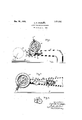
- FIG. 1 is an elevation illustrating a record, a sound box in its inoperative position, and a portion of the sound amplifying system, embodying my invention, the sound box being also shown in operative position in dotted lines;
- Fig. 2 is an enlarged detail view of Fig. 1, partly in section, with the sound box shown in one position of its path of move- Serial No. 551,880.
- Fig. 3 is a section taken on the line a--a of Fig. 1.
- the numeral 10 indicates a sound box or reproducer, of any well known or suitable construction, hav ing a needle 11 suitably connected with the diaphragm.
- the sound box is connected to and communicates with the outer end of a shorttube 12, the inner end of which is pivotally conected to and communicates with the smaller end of a tubular tapering sound box arm 13, which in .turn communicates with any suitable amplifier, not shown.
- the arm 13 is arranged to support the sound box 10 abovethe record tablet 14.
- the sound box 10 is arranged to swing with respect to said arm about a horizontal axis, occupying the position shown in full lines in Fig. 1, when not in use, and the position shown in dotted lines, in the same figure, when in use.
- the tube 12 carries at its inner end a disc 15, which is partially rotated by the swinging movement of the sound box.
- 1 provide means to automatically control the swinging movement of the sound box 10.
- the dash-pot is formed with a cylinder 17, having an external fiat surface 18 on. one side, shown in Fig. 3, to serve as a seat for the cylinder.
- the arm 13 is formed with a similar external flat surface 19, against which the surface 18 is pivotally held by a screw 20, shown in 8.
- the cylinder 17 is provided with a standard type of outwardly opening ball valve.
- a piston 22 is fitted in the cylinder, and is secured to one end of a pitman 23. The opposite end of this pitman is eccentrically connected to the disc 15. By this arrangement the piston is operated by the swinging movement of the sound box 10.
- the piston When the sound box is in its inoperative position, that is, elevated as shown in full lines in Fig. 1, the piston is nearest the closed end of the cylinder 1'7, as indicated in dotted lines at 24 111 Fig. 2. As the sound box is lowered toward the record, the piston moves outwardly, but very gradually, since the ball valve 21 is closed, thus preventing the rapid falling of the sound box to the record. However, when the sound box has reached a position in which the needle is almost touching the record as shown in Fig. 2, the sound box is relieved of the dampening action of the dash.- pot 16, a small opening 25, suitably located in the wall of cylinder 17 being provided for this purpose.
- the dash-pot 17 he dampening action of the dash-pot 17 is eilective until the'ncedle has reached a point from which its drop to the record would cause no injury and at this point it isfreed of said action in order that the needle may :treelytake its place on the record.
- the record tablet isgenera-lly somewhat Warped so that it rises and falls slightly underneath the needle and the latter together with the sound box, has t-o'yield easily to thisup and down movement.
- the pitman 23- is slightly slotted at its outer end at 26 and is loosely con? nected to the disc 15 by apin. From its operative position, the sound 13 1; may be readily raised to its inoperative position, since-the ball valve 21 is opened by the hack- Ward stroke of the dash-pot piston.
- a record tablet a sound arm, a sound 'box pirotally secured to said arm, and means for retard ing themovement of the sound ho ⁇ ; toward the record tahleh said means comprising a dash-pot, saiddash pot provided with a port for increasing the intake of the d'ashqaot when the sound'hox approaches the table. to relieve the sound box from the retarding e'fiect of the dash-pot.
Landscapes
- Details Of Valves (AREA)
- Details Of Rigid Or Semi-Rigid Containers (AREA)
- Reverberation, Karaoke And Other Acoustics (AREA)
Description
Dec. 18 1923.
c. R. KRUEGQR SOUND REPRODUCING MACHINE Filed April 12. 1922 Patented Dec. '18, 1923.
UNETED STATlELd cl rics.
CARL R. KRUEGER, OF RENO, NEVADA, ASSIG-NOR TO GENERAL ELECTRIC COMPANY, A CORPORATION OF NEW YORK.
SOUND-REPRODUCING MACHINE.
Application filed April 12, 1922.
To (all whom it may concern-.-
Be it known that I, CARL R. kmmsnn, a citizen of the Jnited States, residing at Reno, in the county of Washoe, State of Nevada, have invented certain new and useful Improvements in Sound-Reproducing Ma chines, of which the following is a specification.
My invention has reference to improvements in sound reproducing machines. More specifically it relates to a device for controlling the movement of the sound box or reproducer to the sound record.
In sound reproducing machines, the sound box or reproducer, which primarily consists of a diaphragm and a needle in vibratory relation therewith, is suitably connected to an amplifying system, which usually consists of one or a number of sound horns. The sound box is arranged to be moved to bring its needle into engagement with the sound record groove. This movement is usually accomplished by pivotally connecting the sound box to the sound horn, and manually lowering and raising the sound box toengage and disengage the needle with the sound record. The needle is an exceedingly delicate instrument, particularly the new types of tungsten needles, and unless the sound box is moved with care, the needle is likely to be broken and the sound box and the record damaged. In using these machines, the sound box is frequently permitted to fall on the record, either by accident or due to carelessness of the operator with the resultant damages above indicated. In order toovercome these difiiculties, I provide a device to retard the downward movement of the sound box to the record, and in the preferred form of my invention, employ a dash-pot mechanism for this purpose.
My invention will be better understood from the following description takenin connection with the accompanying drawings and its scope will be pointed out in the ap-.
pended claim.
In the accompanying drawings,
'Fig. 1 is an elevation illustrating a record, a sound box in its inoperative position, and a portion of the sound amplifying system, embodying my invention, the sound box being also shown in operative position in dotted lines; Fig. 2 is an enlarged detail view of Fig. 1, partly in section, with the sound box shown in one position of its path of move- Serial No. 551,880.
ment toward the record; and Fig. 3 is a section taken on the line a--a of Fig. 1.
Referring to the drawings,the numeral 10 indicates a sound box or reproducer, of any well known or suitable construction, hav ing a needle 11 suitably connected with the diaphragm. The sound box is connected to and communicates with the outer end of a shorttube 12, the inner end of which is pivotally conected to and communicates with the smaller end of a tubular tapering sound box arm 13, which in .turn communicates with any suitable amplifier, not shown. The arm 13 is arranged to support the sound box 10 abovethe record tablet 14. The sound box 10 is arranged to swing with respect to said arm about a horizontal axis, occupying the position shown in full lines in Fig. 1, when not in use, and the position shown in dotted lines, in the same figure, when in use. The tube 12 carries at its inner end a disc 15, which is partially rotated by the swinging movement of the sound box. The parts thus far described are a standard construction and form no part of my invention.
In carrying out my invention, 1 provide means to automatically control the swinging movement of the sound box 10. For
this purpose, I may employ any suitable dampening or retarding device; however, 1 preferably employ a dash-pot, indicated by the numeral 16, The dash-pot is formed with a cylinder 17, having an external fiat surface 18 on. one side, shown in Fig. 3, to serve as a seat for the cylinder. The arm 13 is formed with a similar external flat surface 19, against which the surface 18 is pivotally held by a screw 20, shown in 8. At its closed end the cylinder 17 is provided with a standard type of outwardly opening ball valve. A piston 22 is fitted in the cylinder, and is secured to one end of a pitman 23. The opposite end of this pitman is eccentrically connected to the disc 15. By this arrangement the piston is operated by the swinging movement of the sound box 10. When the sound box is in its inoperative position, that is, elevated as shown in full lines in Fig. 1, the piston is nearest the closed end of the cylinder 1'7, as indicated in dotted lines at 24 111 Fig. 2. As the sound box is lowered toward the record, the piston moves outwardly, but very gradually, since the ball valve 21 is closed, thus preventing the rapid falling of the sound box to the record. However, when the sound box has reached a position in which the needle is almost touching the record as shown in Fig. 2, the sound box is relieved of the dampening action of the dash.- pot 16, a small opening 25, suitably located in the wall of cylinder 17 being provided for this purpose. he dampening action of the dash-pot 17 is eilective until the'ncedle has reached a point from which its drop to the record would cause no injury and at this point it isfreed of said action in order that the needle may :treelytake its place on the record. The record tablet isgenera-lly somewhat Warped so that it rises and falls slightly underneath the needle and the latter together with the sound box, has t-o'yield easily to thisup and down movement. For this purpose the pitman 23-is slightly slotted at its outer end at 26 and is loosely con? nected to the disc 15 by apin. From its operative position, the sound 13 1; may be readily raised to its inoperative position, since-the ball valve 21 is opened by the hack- Ward stroke of the dash-pot piston.
n r i 'Wlth the provisions of the patent ,it should be understood that I do not While I have described my int ntion as embodied in concrete form 1 of which is set forth in the annexed claim.
What I claim as new and desire to secure by Letters Patent of the United States, is
In a sound reproducing machine, a record tablet a sound arm, a sound 'box pirotally secured to said arm, and means for retard ing themovement of the sound ho}; toward the record tahleh said means comprising a dash-pot, saiddash pot provided with a port for increasing the intake of the d'ashqaot when the sound'hox approaches the table. to relieve the sound box from the retarding e'fiect of the dash-pot.
In Witness whereof, I have hereunto my hand this 5th day of April, 1922.
CARL n. innusenn.
Priority Applications (1)
| Application Number | Priority Date | Filing Date | Title |
|---|---|---|---|
| US551880A US1477832A (en) | 1922-04-12 | 1922-04-12 | Sound-reproducing machine |
Applications Claiming Priority (1)
| Application Number | Priority Date | Filing Date | Title |
|---|---|---|---|
| US551880A US1477832A (en) | 1922-04-12 | 1922-04-12 | Sound-reproducing machine |
Publications (1)
| Publication Number | Publication Date |
|---|---|
| US1477832A true US1477832A (en) | 1923-12-18 |
Family
ID=24203049
Family Applications (1)
| Application Number | Title | Priority Date | Filing Date |
|---|---|---|---|
| US551880A Expired - Lifetime US1477832A (en) | 1922-04-12 | 1922-04-12 | Sound-reproducing machine |
Country Status (1)
| Country | Link |
|---|---|
| US (1) | US1477832A (en) |
-
1922
- 1922-04-12 US US551880A patent/US1477832A/en not_active Expired - Lifetime
Similar Documents
| Publication | Publication Date | Title |
|---|---|---|
| US1477832A (en) | Sound-reproducing machine | |
| US2025300A (en) | Phonograph | |
| US1489436A (en) | Repeating mechanism for phonographs | |
| US2295904A (en) | Automatic pickup head adjusting device | |
| US1133685A (en) | Talking-machine. | |
| US432462A (en) | white | |
| US1486724A (en) | Repeating device for sound-reproducing machines | |
| US1423360A (en) | Attachment for phonographs | |
| US2541826A (en) | Tone arm positioning mechanism | |
| US1095259A (en) | Escapement-adjustment for clocks. | |
| US1556668A (en) | Record repeater for sound-reproducing instruments | |
| US1340524A (en) | Texsen | |
| US1128021A (en) | Attachment for talking-machines. | |
| US898792A (en) | Disk-record attachment for sound-reproducing machines. | |
| US1417747A (en) | Control means for graphophones | |
| US1483573A (en) | Phonograph appliance | |
| US705165A (en) | Horn-supporting arm for talking-machines. | |
| US1170802A (en) | Sound-reproducing machine. | |
| US1321559A (en) | Sound-reproducing machine | |
| US1276192A (en) | Needle-holder for sound-boxes. | |
| US973205A (en) | Automatic check for phonographs. | |
| US1306182A (en) | Phonograph arm and horn attachment | |
| US1414803A (en) | Phonograph reproducer | |
| US890338A (en) | Automatic stop for phonographs. | |
| US1506160A (en) | Phonograph |