US1475986A - Dental thread holder - Google Patents
Dental thread holder Download PDFInfo
- Publication number
- US1475986A US1475986A US607344A US60734422A US1475986A US 1475986 A US1475986 A US 1475986A US 607344 A US607344 A US 607344A US 60734422 A US60734422 A US 60734422A US 1475986 A US1475986 A US 1475986A
- Authority
- US
- United States
- Prior art keywords
- thread
- stem
- holder
- shank
- head
- Prior art date
- Legal status (The legal status is an assumption and is not a legal conclusion. Google has not performed a legal analysis and makes no representation as to the accuracy of the status listed.)
- Expired - Lifetime
Links
Images

Classifications
-
- A—HUMAN NECESSITIES
- A61—MEDICAL OR VETERINARY SCIENCE; HYGIENE
- A61C—DENTISTRY; APPARATUS OR METHODS FOR ORAL OR DENTAL HYGIENE
- A61C15/00—Devices for cleaning between the teeth
- A61C15/04—Dental floss; Floss holders
- A61C15/046—Flossing tools
Definitions
- C. C. COQKE DENTAL THREAD HOLDER Filed Dec. is. 1922 2 Sheets-Sheet 1 INVENTOR Q.'C.C,OO1Q) Dec. 4, 1923. 1,475,986 c. c. COQKE DENTAL THREAD HOLDER Filed Dec.. 16. 1922 2 Sheets-Sheet 2 N WITNESSES Q Patented Dec. 4, 1923.
- animportant object of this invention is to provide novel means whereby a piece of dental floss or silkimay beheld "in an operative position and moved. longltudinally between ones teeth without the necessity: of the operators hand coming direetly in contact withthe floss; I II 7 Further theinvention forming the sub 'ject matter of'this application aims, to pro vide. a dental cord or-thread'holder whichis ofhighly simplified construction, compact and cheap; to manufacture.
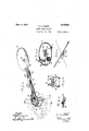
- Figure 1 s a persp dental thread holder
- I I I I Figure 2 is a'planview of'the improved thread holder and reciproc'ator, a part of the thread container being broken away
- II I I Figure 3 is a side elevaJti'oI'i' ofthe 1mprovedfthread holder; parts being Ishown in section
- I I I Figure 4 is a vertical transverse sectional "view taken on' line 1 -51 of Figure 2.
- Figurefi is'an end Fi re .7 is aperspectivej illustrating the cord holding block'which ismou'nted on the cord reciprocating member;
- Figure 8 1s a perspect ve of the main cord I desired movement tothe U-shaped meme holding member.
- the numeral 11 designates a thread container 0f p 'formation
- the parallel arms 14 are providedwith transverse slots 16 which extend out .throughop- 'posite sides of the arms for the reception ofare provided with longitudinal grooves 17 for the reception of the thread or floss.
- the holder 12 which is of U-shaped for? mation is'adaptedto support the cord .l, 5 so that the samemay be drawn between the I teeth for removing food or foreign matter which has lodged between the teeth.
- Figures 1 and ,2 illustrate thatthethread holder 12'maybe'turned about the axis of a pivot bolt 18by a stem 20 having its for- I ward end providedwith a small gear 21' formedon the bight ,po-rtion 2 10f the UE, shaped member 12. It will be .seen that when the stem 20 is-turnedthe gear21 will a V upontthe threads will be urged into engagement with; the edges of ones teeth'for I thoroughly removing those foreign particles which have lodged between the teeth.
- the stem 2O which is connected to the shank 10 by means of bearings'30 maybe rocked by means of oppositely projecting arms 32' secured by means of the attaching portion 33 to the intermediate portion ofthe' stem and the'arms 32 are curved longitudi- 1 nallyt so as to provide a-convenient means ure 5 illustrates that the stem 10 is formed rocked toi an eXte'nt suflicientto impart the ber 12; v
- the cleat' 47 is arranged at one side of the longitudinal center of the head 41 while the pin40 is located at the other side so that when the stem is rocked the cord or thread is reciprocated.
- the gear 21' is formed on the underside of the head 41 and when the head 41 is rocked thelJ-shaped holder 12 is moved about the axis of the pivot pin 18 simultaneously with the longitudinal movement of the tooth contact portion of the thread whereby the teeth arethoroughly and expeditiously cleaned at their opposed to be withdrawn.
- the old thread may be severed at the proper point by means.
- the stem 20 is subsequently rocked for ime parting a rocking motion to the head 41 desirability of the article.
- the device is capable of cleaning the teeth without bringing the hands of the operator di- ,tion taken in connection with the accomrectlyinto contact with the threadand V furthermore it is not necessary toput ones hands into the mouth.
- an extremely sanitary andv eflicient cleaner is provided which is simple to: keep cleanq and cheap to manufacture, all of which contributes to the
- the stem 20 may be retracted slightly when it is'desired to break the connection between the rack 22 and the gear 21 so that I the, position of the member 12 may be changed. This permits the teeth in all parts of the mouth to be cleaned. I Furthermore as illustrated in Figure 7,
- a dental thread holder comprising a U- 99 so thatthef shaped member having a pair of thread holding arms, and a shank pivotally supporting the holder for movement about an axis at right angles to the longitudinalaxis of. the shank.
- a dental thread'holder comprising a shank, a U-shaped threadholdingmember pivoted to the forward portion ofthe shank and having thread holding arms, a thread slidably connected to said arms, and means.
- a dental thread holder comprising a, shank, a thread holder pivoted to the forward portion of the shankand having arms,
- Adental thread holderv comprising a shank, a thread holder pivotedto the .forward portion of the shankand having arms, a thread connected tosaid'arms, a stem roby to rotate saidstem for reciprocating that tatably connected to the shank and having 1 a head, .the opposite edges of which have-f connection with said threa d,'means whereby to rotate said stem for reciprocatingthat.
- a dental thread holder comprising a shank, a thread container connected to the rear portion of the shank, a holder pivoted to the forward portion ofthe shank, and having a pair of parallel arms, a stem extending longitudinally of and rotatably con- & nected to said shank, a head secured to the forward portion of the stem and projecting laterally of the stem, the opposite sides of.
- said head being provided with thread engaging means arranged rearwardly of saidarms, said arms also being provided with thread engaging means, operating members connected to said stem and adapted to be engaged by the hand of the operator in rocking the stem, a rack connected to said thread holding member, a gear secured to said head and engaging said rack for rocking the thread holding member, and a cord cutter associated with the head.
- a dental thread holder comprising a.
Description
- Dec. 4 1923. 1,475,986
C. C. COQKE DENTAL THREAD HOLDER Filed Dec. is. 1922 2 Sheets-Sheet 1 INVENTOR Q.'C.C,OO1Q) Dec. 4, 1923. 1,475,986 c. c. COQKE DENTAL THREAD HOLDER Filed Dec.. 16. 1922 2 Sheets-Sheet 2 N WITNESSES Q Patented Dec. 4, 1923.
i QUN'I'TEDFSTTA es PATENT orrlc cosBY CRITTENDEIN C00KE,I
orLoeAn, wEsT'vIneIN IA.
I DEN AL THREAD HOLDER.
Application filed Deeember 1e, 192a seria n ;eozseaffl 7 T0 azzahbm a m 00mm."
Be it known that I, CosBY C. Coorrn, a citizen of the United States; and'resident of Logan in the county-of Logan and State of pecially adapted for use in cleaning ones teeth. I I r I II Briefly stated animportant object of this invention is to provide novel means whereby a piece of dental floss or silkimay beheld "in an operative position and moved. longltudinally between ones teeth without the necessity: of the operators hand coming direetly in contact withthe floss; I II 7 Further theinvention forming the sub 'ject matter of'this application aims, to pro vide. a dental cord or-thread'holder whichis ofhighly simplified construction, compact and cheap; to manufacture. II
Other objects-and advantages will be'apparentduring the course o'f'th'e following which meshes with the arcuate rack 22' description; I I r I II In the accompanying draw ng, forming a part'of this application, and'in'whlch l ke numerals I are employed" to designate like 1 parts throughout the same;
Figure 1 s a persp dental thread holder, I I I I Figure 2 is a'planview of'the improved thread holder and reciproc'ator, a part of the thread container being broken away, II I I Figure 3 is a side elevaJti'oI'i' ofthe 1mprovedfthread holder; parts being Ishown in section,' I I I Figure 4 is a vertical transverse sectional "view taken on' line 1 -51 of Figure 2. I
Figure 5is a detail sectional view taken on line 5-5015 Figure 2,
Figurefi is'an end Fi re .7 is aperspectivej illustrating the cord holding block'which ismou'nted on the cord reciprocating member;
' Figure 8 1s a perspect ve ofthe main cord I desired movement tothe U-shaped meme holding member.
In the drawing wherein for the purpose of illustration is shown'a preferred embodi;
ment'of the inventiomthe' numeral 10 designates what might b'e'said to be a shank While.
the numeral 11 designates a thread container 0f p 'formation;
the cord and the outer sides of the armslc ecti've of the improved elevation illustrating" the cord holding member,
In carrying: out the invention the shank:
10 has connection at its forward endwithi a holder 12 having spaced parallel arms 14' adapted forholding a piece of thread 15 in an operative position. 'More specifically the parallel arms 14 are providedwith transverse slots 16 which extend out .throughop- 'posite sides of the arms for the reception ofare provided with longitudinal grooves 17 for the reception of the thread or floss.
The holder 12 which is of U-shaped for? mation is'adaptedto support the cord .l, 5 so that the samemay be drawn between the I teeth for removing food or foreign matter which has lodged between the teeth.
In the operationof the improved dental thread holder the U-shaped' member '12-is rotated about a pivot pin 18 by ineansvof which the holderis pivotally connected to the forward'portion of the shank 10.
Figures 1 and ,2 illustrate thatthethread holder 12'maybe'turned about the axis of a pivot bolt 18by a stem 20 having its for- I ward end providedwith a small gear 21' formedon the bight ,po-rtion 2 10f the UE, shaped member 12. It will be .seen that when the stem 20 is-turnedthe gear21 will a V upontthe threads will be urged into engagement with; the edges of ones teeth'for I thoroughly removing those foreign particles which have lodged between the teeth.
The stem 2O which is connected to the shank 10 by means of bearings'30 maybe rocked by means of oppositely projecting arms 32' secured by means of the attaching portion 33 to the intermediate portion ofthe' stem and the'arms 32 are curved longitudi- 1 nallyt so as to provide a-convenient means ure 5 illustrates that the stem 10 is formed rocked toi an eXte'nt suflicientto impart the ber 12; v
whereby. the same maybe engaged by the II I fingersjorthe'thumb ofthe. operator. Fig- I with a recess, 136 to partially receive one-of: l I the, arms 32 wherebythestem 20 may be shaped container 11 receives a quantity of I I II 1051" F igure 2-clearly illustrates thatthefbulb As illustrated in Figure 1 the cord is now trained about a guiding stem 40 formed at one side of the head 41 formed on the forward end of the stem 20. The cord after heing trained about the pin 40 passes down= wardly through one of the grooves 17 and through the slot 16, after which the cord passes up through the other groove 17 and is engaged in a cord holding notch 46 in one side of the head 41. The free end portion of the cord or thread as the case may beis detachably connected to a cleat 47 secured on the upper side of the head.
It will be observed that the cleat' 47 is arranged at one side of the longitudinal center of the head 41 while the pin40 is located at the other side so that when the stem is rocked the cord or thread is reciprocated.
- That is to say whenthe head 41 is rocked as the result of the rotation of the stem, the t about the longitudinal axis of the stem 20 thread will also be moved and that part of the thread between the forward end portions of the arms 14 will be moved backward and forwardly for removing foreign matter from between the teeth. g
It will be observed that the gear 21' is formed on the underside of the head 41 and when the head 41 is rocked thelJ-shaped holder 12 is moved about the axis of the pivot pin 18 simultaneously with the longitudinal movement of the tooth contact portion of the thread whereby the teeth arethoroughly and expeditiously cleaned at their opposed to be withdrawn. Of course when addition-' al thread has been withdrawn the old thread may be severed at the proper point by means.
or" a cutter secured on the head 41 rearwardly of the cleat'47.
When the laterally projecting arms 32 are moved in one direction by the operator they 7 are returnedto their original position by means of a spring member anchored to one section of the bulb-shaped container as indicated at 61 and connected to the laterally projecting member 63 of the stem as in, dicated at 64.
In operation the thread 15 is set for' use in the manner illustrated in Figure 1 and,
the stem 20 is subsequently rocked for ime parting a rocking motion to the head 41 desirability of the article.
whereupon the tooth contact portion of the thread is moved backward andforward for cleaning the teeth. "Simultaneously with the movement of the thread the U-shaped member 12 is moved about the axis of the pin 18 for moving the thread into engagement with all edges of the teeth.
With reference to the foregoing descrippanyin'g drawing it will be apparent that the device is capable of cleaning the teeth without bringing the hands of the operator di- ,tion taken in connection with the accomrectlyinto contact with the threadand V furthermore it is not necessary toput ones hands into the mouth. Thus an extremely sanitary andv eflicient cleaner is provided which is simple to: keep cleanq and cheap to manufacture, all of which contributes to the The stem 20 may be retracted slightly when it is'desired to break the connection between the rack 22 and the gear 21 so that I the, position of the member 12 may be changed. This permits the teeth in all parts of the mouth to be cleaned. I Furthermore as illustrated in Figure 7,
theblock 98 which supports the c'leat 47, is
urged rearwardly by aspring thread is at all times held taut.
Having thus described the invention,
what is claimed is'i- 1. A dental thread holder comprising a U- 99 so thatthef shaped member having a pair of thread holding arms, and a shank pivotally supporting the holder for movement about an axis at right angles to the longitudinalaxis of. the shank. v,
2.A dental thread'holder comprising a shank, a U-shaped threadholdingmember pivoted to the forward portion ofthe shank and having thread holding arms, a thread slidably connected to said arms, and means.
whereby to reciprocate said thread'and simultaneously rock said U-shapedmember.
8. A dental thread holder comprising a, shank, a thread holder pivoted to the forward portion of the shankand having arms,
a thread connected to saidarms, a stem rotatably connected to the shank and having'a head, the opposite edges of which have .con-. nection with said thread, and'mea'ns whereportion of the thread between said cord holding'arm's'. Y I 4. Adental thread holderv comprising a shank, a thread holder pivotedto the .forward portion of the shankand having arms, a thread connected tosaid'arms, a stem roby to rotate saidstem for reciprocating that tatably connected to the shank and having 1 a head, .the opposite edges of which have-f connection with said threa d,'means whereby to rotate said stem for reciprocatingthat.
portion of the threa-d;betwe'en .sai'd' cord holding arms, there being a gear and rack connection between'the- -head and the corda holding member for moving the cord holding member about an axis at right angles to the longitudinal axis of the shank.
5. A dental thread holder comprising a shank, a thread container connected to the rear portion of the shank, a holder pivoted to the forward portion ofthe shank, and having a pair of parallel arms, a stem extending longitudinally of and rotatably con- & nected to said shank, a head secured to the forward portion of the stem and projecting laterally of the stem, the opposite sides of. said head being provided with thread engaging means arranged rearwardly of saidarms, said arms also being provided with thread engaging means, operating members connected to said stem and adapted to be engaged by the hand of the operator in rocking the stem, a rack connected to said thread holding member, a gear secured to said head and engaging said rack for rocking the thread holding member, and a cord cutter associated with the head.
6. A dental thread holder comprising a.
shank, a thread holder pivoted to the-for- T25 ward portion of said shank, a stem mounted on the shank and having a head, there being a gear and rackconnectionbetween said pivoted thread holder andsaid headwherev by the rocking of said stem will turnrsaid thread holder, and means whereby said stem as Y means whereby'a thread maybe connected thereto, said thread holding member being provided with spaced arms between which the thread is extended, and means whereby to rock said head *for reciprocating the thread and turnin'gsaid thread holding member.
cosBY CRITTENDEN cooKE.
Priority Applications (1)
| Application Number | Priority Date | Filing Date | Title |
|---|---|---|---|
| US607344A US1475986A (en) | 1922-12-16 | 1922-12-16 | Dental thread holder |
Applications Claiming Priority (1)
| Application Number | Priority Date | Filing Date | Title |
|---|---|---|---|
| US607344A US1475986A (en) | 1922-12-16 | 1922-12-16 | Dental thread holder |
Publications (1)
| Publication Number | Publication Date |
|---|---|
| US1475986A true US1475986A (en) | 1923-12-04 |
Family
ID=24431881
Family Applications (1)
| Application Number | Title | Priority Date | Filing Date |
|---|---|---|---|
| US607344A Expired - Lifetime US1475986A (en) | 1922-12-16 | 1922-12-16 | Dental thread holder |
Country Status (1)
| Country | Link |
|---|---|
| US (1) | US1475986A (en) |
Cited By (4)
| Publication number | Priority date | Publication date | Assignee | Title |
|---|---|---|---|---|
| DE2923057A1 (en) * | 1979-06-07 | 1980-12-11 | Dolinsky Josef | U=frame teeth cleaning instrument - has parallel silk threads at intervals between arms of frame |
| US5069233A (en) * | 1990-10-30 | 1991-12-03 | Ritter Charles H | Method and apparatus for removing debris from between and around teeth |
| DE4337446C1 (en) * | 1993-11-03 | 1995-03-09 | Henry Wuttke | Adjustable dental cleaning unit |
| US5411041A (en) * | 1993-11-24 | 1995-05-02 | Ritter; Charles H. | Apparatus for removing debris from between and around teeth |
-
1922
- 1922-12-16 US US607344A patent/US1475986A/en not_active Expired - Lifetime
Cited By (4)
| Publication number | Priority date | Publication date | Assignee | Title |
|---|---|---|---|---|
| DE2923057A1 (en) * | 1979-06-07 | 1980-12-11 | Dolinsky Josef | U=frame teeth cleaning instrument - has parallel silk threads at intervals between arms of frame |
| US5069233A (en) * | 1990-10-30 | 1991-12-03 | Ritter Charles H | Method and apparatus for removing debris from between and around teeth |
| DE4337446C1 (en) * | 1993-11-03 | 1995-03-09 | Henry Wuttke | Adjustable dental cleaning unit |
| US5411041A (en) * | 1993-11-24 | 1995-05-02 | Ritter; Charles H. | Apparatus for removing debris from between and around teeth |
Similar Documents
| Publication | Publication Date | Title |
|---|---|---|
| US1852480A (en) | Toothbrush | |
| US2310626A (en) | Motor driven toothbrush | |
| US1475986A (en) | Dental thread holder | |
| US1990404A (en) | Dental appliance | |
| US1880617A (en) | Dental prophylactic oscillator | |
| US1009065A (en) | Sewing device for surgical operations. | |
| US2246730A (en) | Pruning implement | |
| US754841A (en) | Tooth-cleaning implement. | |
| US2644972A (en) | Holder for electrically operated toothbrushes and the like | |
| US2341582A (en) | Machine for cutting edibles | |
| US741519A (en) | Veterinary dental float. | |
| US2160835A (en) | Combined tooth brush and masseur | |
| US1315964A (en) | Hugo jawtsch | |
| US1986371A (en) | Dental floss holder | |
| US1885540A (en) | Brush head swinging device and control | |
| US1681610A (en) | Machine for tying wire ties | |
| US1355309A (en) | Hair-clipper | |
| US1081471A (en) | Key-duplicating machine. | |
| US2095581A (en) | Mechanical tooth brush | |
| US1248778A (en) | Rotatable brush. | |
| US1547092A (en) | Pencil sharpener | |
| US1514420A (en) | Rotary toothbrush | |
| US1457588A (en) | Automatic band-saw filing and setting machine | |
| US858558A (en) | Pencil-sharpener. | |
| SU17086A1 (en) | Modification of the device described in US Pat. No. 7442 |