US1472829A - Card-perforating machine - Google Patents
Card-perforating machine Download PDFInfo
- Publication number
- US1472829A US1472829A US553356A US55335622A US1472829A US 1472829 A US1472829 A US 1472829A US 553356 A US553356 A US 553356A US 55335622 A US55335622 A US 55335622A US 1472829 A US1472829 A US 1472829A
- Authority
- US
- United States
- Prior art keywords
- magnets
- machine
- levers
- keys
- magnet
- Prior art date
- Legal status (The legal status is an assumption and is not a legal conclusion. Google has not performed a legal analysis and makes no representation as to the accuracy of the status listed.)
- Expired - Lifetime
Links
Images


Classifications
-
- G—PHYSICS
- G06—COMPUTING OR CALCULATING; COUNTING
- G06K—GRAPHICAL DATA READING; PRESENTATION OF DATA; RECORD CARRIERS; HANDLING RECORD CARRIERS
- G06K1/00—Methods or arrangements for marking the record carrier in digital fashion
- G06K1/02—Methods or arrangements for marking the record carrier in digital fashion by punching
Definitions
- the invention relates to machines for making a plurality of perforations in a card or other blank and is a preferable embodiment of the principles of my former invention as set forth in my application No. 387,596, filed June 9, 1920 and at present pending.
- the embodiment herein set forth embraces the same principles but possesses many new and ingenious structural features which experiment and investigation have shown to be of great practical and economical value by simplifying construction and operation and increasing accessibility of parts. It is these structural improvements together with certain other original features correlated with them that I desire to protect.
- the objects of the present invention are: to provide means for connecting the magnets armatures, levers and keys in such a way as to allow for a compact and accessible design of machine, to provide means for mounting each gang of magnets in a separate sliding drawer so that it may be removed from the machine in the easiest possible manner, thus greatly promoting accessibility, to provide certain peculiarities of electric wiring correlated with the afore mentioned improvements, to provide means for supporting the levers so that they may remain in position when their controlling magnets are removed from the machine, to provide means for simply and easily reconnecting levers and armatures when magnets are returned to machine after removal, to provide means for easily removing intact the entire wiring system from the main body of the machine when desirable, thus making repairs very easy as well as forming a very economical original design, to provide means for shifting the control from any given magnet to any other magnet or magnets, to provide means for rendering any magnet or magnets inoperative, to provide means for withdrawing the keys from the locking position after each perforation.
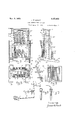
- Figure 1 is a side view of the drawer containing a complete group of magnets, said drawer being shown partly withdrawn out of the normal position in its slide or support.
- Figure 6 and Figure 7 are a front and edge elevation, respectively, of the grid frame for withdrawing the keys to unlock the punchers after each perforation.
- Figure 8 shows a locking key, its lever connecting rod and controlling magnet and illustrates the action of connecting or threading the lever through the annature.
- Figure 9 shows on a larger scale one of the plugs for completing the circuit on the switch board.
- Figure 10 also on a larger scale shows a special form of plug which under certain requirements 7 1s useful for jumping the control from one magnet to another. Similar characters of reference indicate corresponding parts throughout the different figures of the drawing.
- the punch head 1 supports the gang 0 punchers 2, together with the looking keys 3, said keys being controlled throu h the medium of key rods 4 and levers 5 %y the magnets 7, the circular headed end of each lever 5 fitting easily into a suitable slot or eye in its particular armature 6.
- These magnets are mounted in groups or gangs in drawers 8, which are slidable in grooves formed in the standards 9 which support them, as is shown in Figure 2, Figure 3, Figure 4 and Figure 5.
- Each group of magnets being connected with and controlling the keys of its particular horizontal layer of keys 3, as illustrated.
- the foremost upper compartment as shown in Figure 1 contains the magnets controlling the upper layer of keys 3, while the foremost lower compartment vertically beneath controls the lowest layer of keys.
- the second upper drawer 8 holds the magnets controlling the'second highest row of keys 3, and the drawer vertically beneath it contains the magnet controlling the second lowest layer of keys 3, and so on back for the succeeding groups of magnets, the upper row of roups converging towards the lower row.
- Figure 4 and Figure 5 is shown a method of mounting the levers 5 on the lever supports 11 which extend across, between and are secured to each corresponding pair of standards 9.
- the slots between the projecting guides on 11 being suitably spaced to bring the levers 5 in alignment with the slots or eyes in the armature 6, the pivots 12 in the guides being suitabl located so that all the various lengthed evers in the set have the same throw, while the guides are of suflicient dimensions to maintain the levers in correct alignment.
- FIG 3 is also shown the method of wiring the magnets in their containing drawers, so that the latter may be readily withdrawn from the machine.
- Each set of magnets is mounted on the division of its compartment which separates it from the other compartments.
- This division should be a panel 14 of wood or other non-conductin material held in a metal frame 13, one en of the winding of each magnet is connected to this conducting frame as shown in Figure 3, and the other end carried over to and connected with a contact piece or terminal 15, located in a hole in one side 16 of the drawer 8.
- This side 16 must be of non-conducting material and, contains as many holes, each fitted with electrical contact means 15 as there are magnets in the drawer.
- each contact 15 One end of the winding of a magnet is connected to each contact 15
- the contact holes 15 are exactly in line with a similar set of contact holes 15, in a non-conducting panel 17 loosely fitted in recesses in standards 9, so that contact plugs as shown in Figures 9 and 10 enlarged, may be inserted through these contact holes to close a circuit through them.
- the contact nevasae holes 15 in panels 17 are connected each with a conducting wire, said wires passing along the inside of said panel to the middle of the side or cover 18 of the ke rod space where they are twisted together into a cable and attached to 18 and carried horizontally rearward along the middle of 18 until they reach and are properly distributed among the individuals of the groups of binding posts 19 at the rear of the machine.
- These anels 17 are held loosely in position, (a fioating fit), by cleats 22 or other suitable means, the end and side looseness in fit being to allow either a air of removable dowel pins or the plugs themselves to bring the holes 15 and 15 into alignment, if necessary.
- the panels17, side 18 and post groups 19 may all be held in their proper relative positions during and after removal b means of an auxiliary frame or cradle and after the necessary disconnections, may be removed as a whole from the machine, when the intact wiring s stem will be in plain view and very accessible condition.
- Figure 6 and Figure 7 show the grid device for withdrawing the keys 3 from the locking position. It is also shown in its proper position, in Figure 1, located on the back of the punch head 1, where it is capable of oscillating up and down in its inclined position.
- This device consists of a frame 20 supporting in proper position a series of serrated bars; each of these bars 21 acts on two adjacent vertical rows of keys. 3, each key having a recess milled half way through it so that there is a head or edge on the key that may engage with one of the inclined planes or serrated faces on the bars 21.
- the grid frame 20 and the plate 23, Figure 1, for restoring the punches 2 to their normal position are operated simultaneously through the medium of the slide 24, Figure 2, which is actuated through an eccentric or cam 25 and connecting rod 26 mounted on the crank shaft 27, driven by a pulley 28.
- This same crank shaft by means of a connecting rod 36, oscillates the ram 29 up and down in the ways 30 to carry the die 31 up against the punches to perforate the cards.
- plugs, Figure 9 When it is desired to operate all the magnets, plugs, Figure 9, must be placed in each of the holes 15, thus bridging the space between 15- and 15 and continuing the circuit between the wiring in the drawers 8 and.
- plugs corresponding to these magnets must be withdrawn from the machine.
- These plugs may be either solid or made of tubing, or drawn from thin sheet metal and be fitted with non-conducting handles as indicated in Figure 9.
- the plugs of the jumper inserted in the holes jumped to should be of the special form shown in Figur 10, wher the plug is of such form as to be insulated where it makes contact with 15 as it passes through to 15, but makes electrical contact with the latter and carries the current through the center of the insulated part from the flexible conductor, as indicated.
- a card punching machine the combination of a gang of punches and cooperating perforating mechanism, keys for looking the punches, a plurality of groups of electro-magnets, each group being specially mounted in a removable drawer, a plurality of similar groups of levers, means for mounting and pivoting said levers, a plurality of sets of connecting rods, each set corresponding to a group of levers and keys, means for easily connecting said levers to armatures of said magnets, electric wlring means specially adapted for easy removal of magnets, all substantially as specified.
- a card punching machine the combination of a gang of punches and cooperating perforating mechanism, means for individually locking said punches in operative condition, a plurality of groups of electroma ets for actuating the locking means, eac group of magnets being mounted in a removable drawer suitably supported in a bay or compartment, means for grouping said bays or compartments in the most compact and accessible form, electric circuit means adapted to easy removal or insertion of magnet-holding drawers, means for shift ing or jumping the control of any magnet from one circuit to any other circuit, means for cutting out or rendering any magnet or magnets inoperative, all substantially as described.
- a card punching machine the combination of a gang of punches, a plurality of keys for locking the punches in operative condition individually, a plurality of groups of levers, each group being similar to every, other group, a plurality of sets of connecting rods, the rods of each set being of equal length but difiering from the length of any other set, a plurality of roups of electromagnets each so mounted and arranged as to be easily withdrawn from the machine, means for supporting said groups so as to allow their easy removal, means for supporting the levers so they may remain in position when their controlling magnets are removed, means for easily connecting the levers with the magnets, electric wiring means conforming to the condition of easy removal of the magnets from the machine, means for unlocking punches, all substantially as specified.
- a card punching machine the combination of a gang of punches with cooperating punching mechanism, means for looking the punches, means for unlocking the punches, a plurality of similar groups of magnets for actuating the locking means, means for easily removing the groups of magnets, means for supporting and arranging the groups of magnets in the most compact and accessible form, electric wiring means suitable for the quick and easy .removal of groups of magnets, means for shifting or jumping the control of any magnet from one circuit to another, means for adding one or more magnets to any circuit, means for rendering any magnet or magnets inoperative, all substantially as described.
Landscapes
- Physics & Mathematics (AREA)
- General Physics & Mathematics (AREA)
- Engineering & Computer Science (AREA)
- Theoretical Computer Science (AREA)
- Mounting Of Printed Circuit Boards And The Like (AREA)
Description
.1. H. GAULT CARD PERFORAT ING MACHINE Nov. 6, 1923.
Filed April 1'7, 1.922 5 Sheets-Sheet 1 INVENTUR Nov. 6, 1923.
J. H. GAULT CARD PERFORATING MACHINE Filed April 17 1922 3 Sheets-Sheet 2 INVENTUF? Nov. 6, 1923. 1,472,829
J. H. GAULT CARD PERFORATING MACHINE Filed April 17, 1922 3 SheetS-Sheet 5 INVENTQR fa/MM 44M Patented Nov. 6, 1923.
JAMES H. GAULT, or PHILADELPHIA, rnmrsynvmm.
CARD-PERFORATING MACHINE.
Application filed April 17, 1922. Serial No. 553,858.
To all whom it may concern:
Be it known that I, JAMES H. GAULT, a citizen of the United States, residing at Philadelphia, in the county of Philadelphia and State of Pennsylvania, have invented certain new and useful Improvements in Card-Perforating Machines, of which the following is a specification.
The invention relates to machines for making a plurality of perforations in a card or other blank and is a preferable embodiment of the principles of my former invention as set forth in my application No. 387,596, filed June 9, 1920 and at present pending. The embodiment herein set forth embraces the same principles but possesses many new and ingenious structural features which experiment and investigation have shown to be of great practical and economical value by simplifying construction and operation and increasing accessibility of parts. It is these structural improvements together with certain other original features correlated with them that I desire to protect.
Specifically the objects of the present invention are: to provide means for connecting the magnets armatures, levers and keys in such a way as to allow for a compact and accessible design of machine, to provide means for mounting each gang of magnets in a separate sliding drawer so that it may be removed from the machine in the easiest possible manner, thus greatly promoting accessibility, to provide certain peculiarities of electric wiring correlated with the afore mentioned improvements, to provide means for supporting the levers so that they may remain in position when their controlling magnets are removed from the machine, to provide means for simply and easily reconnecting levers and armatures when magnets are returned to machine after removal, to provide means for easily removing intact the entire wiring system from the main body of the machine when desirable, thus making repairs very easy as well as forming a very economical original design, to provide means for shifting the control from any given magnet to any other magnet or magnets, to provide means for rendering any magnet or magnets inoperative, to provide means for withdrawing the keys from the locking position after each perforation.
A practical embodiment of my invention is represented in the accompanying drawings in which Figure 1 is a side view of the drawer containing a complete group of magnets, said drawer being shown partly withdrawn out of the normal position in its slide or support. These three views fully illustrate in detail the method of grouping and wiring the magnets as well as that of supporting the levers. Figure 6 and Figure 7 are a front and edge elevation, respectively, of the grid frame for withdrawing the keys to unlock the punchers after each perforation. Figure 8 shows a locking key, its lever connecting rod and controlling magnet and illustrates the action of connecting or threading the lever through the annature. Figure 9 shows on a larger scale one of the plugs for completing the circuit on the switch board. Figure 10 also on a larger scale shows a special form of plug which under certain requirements 7 1s useful for jumping the control from one magnet to another. Similar characters of reference indicate corresponding parts throughout the different figures of the drawing.
In Fi re 1 the punch head 1 supports the gang 0 punchers 2, together with the looking keys 3, said keys being controlled throu h the medium of key rods 4 and levers 5 %y the magnets 7, the circular headed end of each lever 5 fitting easily into a suitable slot or eye in its particular armature 6. These magnets are mounted in groups or gangs in drawers 8, which are slidable in grooves formed in the standards 9 which support them, as is shown in Figure 2, Figure 3, Figure 4 and Figure 5. Each group of magnets being connected with and controlling the keys of its particular horizontal layer of keys 3, as illustrated. The foremost upper compartment as shown in Figure 1 contains the magnets controlling the upper layer of keys 3, while the foremost lower compartment vertically beneath controls the lowest layer of keys. The second upper drawer 8 holds the magnets controlling the'second highest row of keys 3, and the drawer vertically beneath it contains the magnet controlling the second lowest layer of keys 3, and so on back for the succeeding groups of magnets, the upper row of roups converging towards the lower row. he step formed side beams 10, Figure 2, each step of which supports a stan ard 9, shows this convergence towards the rear of the machine, the vertical distance of each step being equal to the distance between any two successive layers of keys 3. Bfy this plan of construction the advantage 0 having each set of levers 5 a duplicate of every other set is secured, the danger of any lever interfering with the rod controlled by any other lever is avoided, and compactness of design is also obtained. In Figure 2 it is-seen that the entire system of magnets is supported upon a pair of parallel beams 10 secured at the front to the punching ress 33 and at the rear resting on a pair of legs 34, this construction allowing perfect accessibility to the drawers 8 and plenty of space to remove them from the machine.
In Figure 3, Figure 4 and Figure 5 is shown a method of mounting the levers 5 on the lever supports 11 which extend across, between and are secured to each corresponding pair of standards 9. The slots between the projecting guides on 11 being suitably spaced to bring the levers 5 in alignment with the slots or eyes in the armature 6, the pivots 12 in the guides being suitabl located so that all the various lengthed evers in the set have the same throw, while the guides are of suflicient dimensions to maintain the levers in correct alignment.
In Figure 3 is also shown the method of wiring the magnets in their containing drawers, so that the latter may be readily withdrawn from the machine. Each set of magnets is mounted on the division of its compartment which separates it from the other compartments. This division should be a panel 14 of wood or other non-conductin material held in a metal frame 13, one en of the winding of each magnet is connected to this conducting frame as shown in Figure 3, and the other end carried over to and connected with a contact piece or terminal 15, located in a hole in one side 16 of the drawer 8. This side 16 must be of non-conducting material and, contains as many holes, each fitted with electrical contact means 15 as there are magnets in the drawer. One end of the winding of a magnet is connected to each contact 15 When the drawer 8 is completely home in its normal position in the ways of standards 9, the contact holes 15 are exactly in line with a similar set of contact holes 15, in a non-conducting panel 17 loosely fitted in recesses in standards 9, so that contact plugs as shown in Figures 9 and 10 enlarged, may be inserted through these contact holes to close a circuit through them. The contact nevasae holes 15 in panels 17 are connected each with a conducting wire, said wires passing along the inside of said panel to the middle of the side or cover 18 of the ke rod space where they are twisted together into a cable and attached to 18 and carried horizontally rearward along the middle of 18 until they reach and are properly distributed among the individuals of the groups of binding posts 19 at the rear of the machine. These anels 17 are held loosely in position, (a fioating fit), by cleats 22 or other suitable means, the end and side looseness in fit being to allow either a air of removable dowel pins or the plugs themselves to bring the holes 15 and 15 into alignment, if necessary.
If it is desired to remove the wiring system intact from the machine the panels17, side 18 and post groups 19 may all be held in their proper relative positions during and after removal b means of an auxiliary frame or cradle and after the necessary disconnections, may be removed as a whole from the machine, when the intact wiring s stem will be in plain view and very accessible condition. I
Figure 6 and Figure 7 show the grid device for withdrawing the keys 3 from the locking position. It is also shown in its proper position, in Figure 1, located on the back of the punch head 1, where it is capable of oscillating up and down in its inclined position. This device consists of a frame 20 supporting in proper position a series of serrated bars; each of these bars 21 acts on two adjacent vertical rows of keys. 3, each key having a recess milled half way through it so that there is a head or edge on the key that may engage with one of the inclined planes or serrated faces on the bars 21. When the keys 3 are in their normal or unlocked position the grid has no effect on them, but when pushed forward into the locked position, the edge of the recess in the key is ushed up against the lower face of one of the inclined planes or serrations on the bar 21, so that when the frame 20 next carries down the bar the serration acting on the edge of the key head withdraws the keys to the unlocked position.
The grid frame 20 and the plate 23, Figure 1, for restoring the punches 2 to their normal position are operated simultaneously through the medium of the slide 24, Figure 2, which is actuated through an eccentric or cam 25 and connecting rod 26 mounted on the crank shaft 27, driven by a pulley 28. This same crank shaft, by means of a connecting rod 36, oscillates the ram 29 up and down in the ways 30 to carry the die 31 up against the punches to perforate the cards.
When it is desired to operate all the magnets, plugs, Figure 9, must be placed in each of the holes 15, thus bridging the space between 15- and 15 and continuing the circuit between the wiring in the drawers 8 and.
the part of the circuit outside the compartment. If it is desired to leave any magnet or number of magnets inoperative, the plugs corresponding to these magnets must be withdrawn from the machine. These plugs may be either solid or made of tubing, or drawn from thin sheet metal and be fitted with non-conducting handles as indicated in Figure 9.
When it is desired to jump the circuit normally controlling any given magnet to any other magnet or magnets, two or more plugs are connected by flexible conductors as illustrated by 32, Figure 1. Two or more plugs thus connected by flexible conductors are called jumpers. If it is desired in any given case to cut out the magnet normally controlled by any given hole 15 While jumping its regularly controlling circuit to other magnets, the jumper plug placed in the given hole should not be inserted in 15 deep enough to reach through to 15. If it is desired to shift the control from any hole 15 to another hole or holes so that the hole shifted from shall be the sole control and the circuits normally controlling the holes jumped to, shall be cut off, then the plugs of the jumper inserted in the holes jumped to should be of the special form shown in Figur 10, wher the plug is of such form as to be insulated where it makes contact with 15 as it passes through to 15, but makes electrical contact with the latter and carries the current through the center of the insulated part from the flexible conductor, as indicated.
When it is necessary for any reason to remove any gang or group of magnets from the machine, all that is necessary is to pull out all of its corresponding plugs a sulficient distance to clear its side 16, and then to remove it from the machine like a vertical drawer. To replace it all of the armatures 6 should be pushed into their magnets as far as they will go. while all the corre sponding levers 5 should be pushed back to their normal (vertical) position, so that when the drawer is replaced the armatures and levers will clear each other durin the movement: then each lever 5 is lifted om its pivot 12, carried down under its particular armature 6. inserted in the eye or slot of the armature, as shown in Figure 8, and replaced on its pivot. The ends of drawers 8 should be easily removable to allow access for this re-connection of armatures and levers.
In the present embodiment of my invention no means of automatically feeding either the master or blank cards is indicated, nor is there any provision here shown for the controlling contact points which are acted upon at the rear of the machine b the master cards, as the improvements wish to protect do not involve any of these features and their introduction was not necessary to illustrate'these improvements. It is evident that the machine as shown is capable of having applied to it either the feeding and contact means shown in m original invention hereinbefore mentione or in fact, any of the numerous card-feedin and contact-making means now in genera use which may vary according to the particular phase of the art in which the machine is to be employed. In cases where contact means are of suitable type and where it is not desired to frequently change from one contactmeans to another, the binding posts 19 may be omitted, the wires passing through and being held directly in the contact device.
What I claim as my invention and desire to secure by Letters Patent is: I
1. In a card punching machine the combination of a gang of punches and cooperating perforating mechanism, keys for looking the punches, a plurality of groups of electro-magnets, each group being specially mounted in a removable drawer, a plurality of similar groups of levers, means for mounting and pivoting said levers, a plurality of sets of connecting rods, each set corresponding to a group of levers and keys, means for easily connecting said levers to armatures of said magnets, electric wlring means specially adapted for easy removal of magnets, all substantially as specified.
2. In a card punching machine the combination of a gang of punches and cooperating perforating mechanism, means for individually locking said punches in operative condition, a plurality of groups of electroma ets for actuating the locking means, eac group of magnets being mounted in a removable drawer suitably supported in a bay or compartment, means for grouping said bays or compartments in the most compact and accessible form, electric circuit means adapted to easy removal or insertion of magnet-holding drawers, means for shift ing or jumping the control of any magnet from one circuit to any other circuit, means for cutting out or rendering any magnet or magnets inoperative, all substantially as described.
3. In a card punching machine, the combination of a gang of punches, a plurality of keys for locking the punches in operative condition individually, a plurality of groups of levers, each group being similar to every, other group, a plurality of sets of connecting rods, the rods of each set being of equal length but difiering from the length of any other set, a plurality of roups of electromagnets each so mounted and arranged as to be easily withdrawn from the machine, means for supporting said groups so as to allow their easy removal, means for supporting the levers so they may remain in position when their controlling magnets are removed, means for easily connecting the levers with the magnets, electric wiring means conforming to the condition of easy removal of the magnets from the machine, means for unlocking punches, all substantially as specified.
4. In a card punching machine, the combination of a gang of punches with cooperating punching mechanism, means for looking the punches, means for unlocking the punches, a plurality of similar groups of magnets for actuating the locking means, means for easily removing the groups of magnets, means for supporting and arranging the groups of magnets in the most compact and accessible form, electric wiring means suitable for the quick and easy .removal of groups of magnets, means for shifting or jumping the control of any magnet from one circuit to another, means for adding one or more magnets to any circuit, means for rendering any magnet or magnets inoperative, all substantially as described.
5. In a card perforating machine the combination of a. gang of punches, a plurality of keys for locking the punches in operative condition individually, a plurality of groups of levers, each group being similar to every other group, a. plurality of sets of connecting rods, the rods of any set bein all of the same length, but the lengths of t e various sets being different from each other, a plurality of groups of electro-magnets, each group being mounted removably in a separate bay or compartment, standards supporting saidgroups in proper operative position and in such manner as to allow their easy removal from the machine, means for supporting and pivoting levers so that they may remain undisturbed in operative position when their controlling magnets are removed, means for reconnecting the levers with their armatures when the magnets are returned, electric wiring means conforming to condition of easy removal of ma nets, means for supporting the standar s and entire electric system between the punching head and rear support, means for withdrawing the keys from a locking position, means for cutting out or rendering inoperative any magnet or a. group of magnets, means for jumping or shifting a circuit from any given magnet to an other magnet, means for removing the entire wiring system intact from the machine, all substantially as specified.
In testimony whereof I afiix my signature.
JAMES H. GAULT.
Priority Applications (1)
| Application Number | Priority Date | Filing Date | Title |
|---|---|---|---|
| US553356A US1472829A (en) | 1922-04-17 | 1922-04-17 | Card-perforating machine |
Applications Claiming Priority (1)
| Application Number | Priority Date | Filing Date | Title |
|---|---|---|---|
| US553356A US1472829A (en) | 1922-04-17 | 1922-04-17 | Card-perforating machine |
Publications (1)
| Publication Number | Publication Date |
|---|---|
| US1472829A true US1472829A (en) | 1923-11-06 |
Family
ID=24209099
Family Applications (1)
| Application Number | Title | Priority Date | Filing Date |
|---|---|---|---|
| US553356A Expired - Lifetime US1472829A (en) | 1922-04-17 | 1922-04-17 | Card-perforating machine |
Country Status (1)
| Country | Link |
|---|---|
| US (1) | US1472829A (en) |
-
1922
- 1922-04-17 US US553356A patent/US1472829A/en not_active Expired - Lifetime
Similar Documents
| Publication | Publication Date | Title |
|---|---|---|
| US999991A (en) | Filing and indexing appliance. | |
| US1472829A (en) | Card-perforating machine | |
| US2502960A (en) | Record controlled punching machine | |
| GB1006876A (en) | A record sensing device in selective printers and like data processing equipment | |
| US2061745A (en) | Electrical adding machine | |
| US1950476A (en) | Card perforating machine | |
| US1763067A (en) | Punching device | |
| US1298400A (en) | Machine operating mechanism. | |
| US2342361A (en) | Statistical card system | |
| US2044708A (en) | Card punching machine | |
| US2003637A (en) | Record controlled punching machine | |
| US2080192A (en) | Verifying punch machine for duplicate cards | |
| US2002516A (en) | Tape perforating machine | |
| US1318662A (en) | Planooraph co | |
| US2129782A (en) | Record puncturing machine | |
| US1473618A (en) | Card-punching machine | |
| US2314718A (en) | Accounting apparatus | |
| US1827002A (en) | Perforating device | |
| US2703617A (en) | Record card reproducing punch | |
| US1085985A (en) | Keyboard tape-perforator. | |
| US2004208A (en) | Punching machine | |
| US1684001A (en) | Alphabetical keyboard punch | |
| US1401201A (en) | Music-roll-perforating machine | |
| US2490360A (en) | Perforated record sensing device | |
| US986479A (en) | Card-punching machine. |