US1459662A - Lubricating system - Google Patents
Lubricating system Download PDFInfo
- Publication number
- US1459662A US1459662A US404300A US40430020A US1459662A US 1459662 A US1459662 A US 1459662A US 404300 A US404300 A US 404300A US 40430020 A US40430020 A US 40430020A US 1459662 A US1459662 A US 1459662A
- Authority
- US
- United States
- Prior art keywords
- nipple
- pump
- bearing
- lubricant
- nozzle
- Prior art date
- Legal status (The legal status is an assumption and is not a legal conclusion. Google has not performed a legal analysis and makes no representation as to the accuracy of the status listed.)
- Expired - Lifetime
Links
Images

Classifications
-
- F—MECHANICAL ENGINEERING; LIGHTING; HEATING; WEAPONS; BLASTING
- F16—ENGINEERING ELEMENTS AND UNITS; GENERAL MEASURES FOR PRODUCING AND MAINTAINING EFFECTIVE FUNCTIONING OF MACHINES OR INSTALLATIONS; THERMAL INSULATION IN GENERAL
- F16N—LUBRICATING
- F16N3/00—Devices for supplying lubricant by manual action
- F16N3/10—Devices for supplying lubricant by manual action delivering grease
- F16N3/12—Grease guns
Definitions
- This invention relates to a lubricating system designed more particularly for sup-4 plying the variousbearings of automobiles, vmotor-trucks, tractors and similar vehicles.
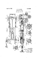
- Figure 1 is a top plan view of anautomolbile equipped with -the 'improved'lubricating s stem, the gure 2 is 4e. a longitudinal section, on an-enlarged scale,
- FIG. 7 is cross inglyfnuinberedV linesV in' Fig. 7.
- igure 7 is a longitudinal section, of al' lof the'motor car are replaced by feed-nip i .ples 11, one of these bearings and its feed nipple being shown in vertical section in Fig. 2.
- This bearing isof the roller type and therefore lubricated withgrease. It has the customary internally threaded connection 12 for receiving the feed nipple 11, which has a stem or neck 13 to which it is detachably connectedby a screw threaded joint, as shown, or by other suitable means.
- This neck may be straight or curved, according to the location of the bearing, to render the nipple most accessible -to the discharge nozzle ofthe oilor grease n, :1s-hereinafter more fully described.
- this neck or stem 13 is flexible, softhatit. can belbent into any desired position or' atthe' most convenient angle to facilitate access to it by For this' u nipple-neckmay be constructe o a suitable. flexible material, as annealed steel,
- Each of these nipples is provided with a central inlet-orifice 14 ⁇ wh1ch is n ormall ⁇ closed by an internal check-valve 15, pre
- the stop' shown. in the drawings consists of a fixed in 15a arranged axlally lnsaid neck an extending forwardly Afrom a bridge ⁇ piece 15b extending across its throat. ⁇ The springofl the check valve surrounds this pin. l
- a vcomparatively long andl slender gun or force pump is employed having a sliding piston and a tubular guide ⁇ or centering nozzle 16 at Aits front end which is adapted to slip over the feed nipple and which rigidly' connected to the pumps body.
- This nozzle is controlled by and engaged with the nipple by the pump itself which serves as a long handle for this purpose, enabling remote bearings to be conveniently reached through any accessible space without the necessity of going or reaching under the car and soiling the hands y tending practically throughout the length of the vbarrel and providedin its 4side'with a filling slot or aperture 23 through which the magazine is filled with grease with a spoon or similar implement.
- the rear cap 18 is unscrewed from the pump barrel and the magazinev is withdrawn therefrom. The plunger is then drawn back beyond the rear end of said filling aperture,
- nipple 25 Projecting centrally from the front head' 19 of the ump-barrel is a hollow neck 24 with which engages the hollow stem of ra discharge nipple 25.
- This nipple ' carries the guide-nozzle 16 of the pump which projects beyond said nipple, these parts-being preferably united by screw threaded joints, as shown in Fig. 2.
- a packing washer or gasket 26 Housed within the vguide nozzle and seated against the face of the pump nipple 25 4is a packing washer or gasket 26 of rubber or other/appropriate material, the bore of which registers with the bore of said nipple and which is ⁇ adapted to seatv against the head 'of -anyone of the feed-nipples 10.
- This acking preferablj7 consists of fa number o disks or laminations of oil proof ,material
- the delivery end of the pump barrel and the :receiving end of the'bearing-nipple are provided with complementary means, whereby a sealed, lubricant-tight connection may be effected between said elements solely by the appli-l cation ofpressure lengthwise of the pump- -barrel and without the use of means for positively coupling the pump to the nipple.
- the most satisfactory results are obtained when either the face of the packing gasket 26 or4 the receivingl lend 'of the nipple 25is made convex, or when both of these parts have that contour, as shown in the drawings.
- the central portion' of the comparatively hardor rigid bearin ⁇ nipple compresses the central portion o the yielding or less rigid packing sket and temporarily changes its' contour. nlargement orspreading Vof the contact vrim between the front end of the gu ov the guide 'passage of the area between these parts is thus avoided, and I vsuch contactis confined to an area less than that of the pump-piston, thereby insuring. the necessary preponderance of the longitudinal pressure on the pump, exerted y the operator, over the resistance orl backpressure tending to break the seal or.joint i between the pump and the lbearing nipple.;-
- the pump is .quick y separable from said nipple by simply relieving the forward pressureon the pump and withdrawing itsV guide nozzle: from the nipple, thus render- ,ing it unnecessary to' reach under Ithe car toy apply or remove said nozzle directly by hand.
- the 4desired centralbulge is obtained by tightly clamping' its n-nipple 42 and an internal shoulder43* nozzle 43, as shown in Figs. l2 and 7.
- the guide nozzle preferably has a flared mouth and is fitted somewhat loosely onthe bearin'g nipple, and asl the face of the latter is F convex, the nozzle is, free to rock or swivel A thereon to a limited extent, facilitating the engagement of the nozzle therewith.
- a fixed c o're or stem 27 carried b the discharge-nipple 25,. extends throug said bore, as shown in Fig. 2.
- the pro-v jecting front ortion of this core is reduced and provide lthroughout its length with longitudinal grooves or channels 28 -for lthe vgrease iinto thel bearing In lubricating a-'bearing with this grease' gun, after filling the magazine 22 and .re- ⁇
- the pump is joined to the4 bearing-nipple by passing its guide nozzle 14 over said nipple and the plunger is then pushed forward a. greater or less distance, according to the amount of the plunger handle is transmitted through ;the grease and the pump-body to the packing gasket, which 'is'thereby ⁇ firmly. ressed against the end of ⁇ the bearing-nipp e, producng a .tight and reliable seal, as before ase required- V Y by the bearing, some bearrriegs requiring more than others.
- This pressure -against vbearings at a'pressure for example, of 300() 30 l.
- the pump-nozzle 14 serves not only to guide the end of the pump onto the bearing nipple, but also holds it against lateral displacement thereon.
- the plungerrod may-be provided with an adjustable gage or stop 29 adapted to of the pump barrel.
- the gage shown in t e. drawings consists of a split collar which ti htly embraces the said rod and is held inp ace by friction. If del sired, the plunger rod may be provided with a scale withwhich the gage collar coop erates.
- a bearing-nipple should not extend in the proper direction or stand at the proper angle .-to conveniently receive the guidenozzle of the pump, said nipple on account of its flexibility can be bent to the desired angleby means of said nozzle and the pump body, or by a separate tube of the proper length and size to reach and lit over the bearing-nipple.
- connection 24 between the guide nozzle 16 and the pump-body isrigid and that the'pump bod)T itself forms an extended Ihandle by which the nozzle is'successively engaged with.
- the several bearing-nipples of an lautomobile or other piece ofl mechanism renders it possible not only to quickly join the guide nozzleto the bearing-nipple at a distance and without the necessity of reaching under the car and doing so directly with the hands, but it also enables pressure to be conveniently exerted by meanslof the plunger and the pump body inthe longitudinal direction of said nozzle and nipple to insure a tight joint between them and eifectually prevent leakage of the lubricant at that point.
- the lubricating operation is not only more convenient and cleaner, but an important saving lof time is effected by reason of the absence of coupling"devices and :he use of a sliding or push-button, lenabling a large number of such bearings to be quickly lubricated with-ease.
- a longitudinal pump-barrel 40 Arranged in the front portion of the oil cylinder is a longitudinal pump-barrel 40 in which the plunger 36 reciprocates and which -is provided in its walls with oill inlet ports 41 communicating with said cylin ⁇ der, oil being drawn through these-ports on the suction or return stroke of the pump and the ports bein closed by the plunger onits forward stroe to eject the oil.
- the barrel 40 v extends through and beyond the front head 33 and terminates in a nipple 42 similar to the nipple 27. This nipple in turn carries a 45 of said nozzle when the gun or the plunger is pushed toward it.
- the nipple '42 of the pump barrel contains a suitable check valve 46 to prevent the escape of oil from the pump when Anot engaged with a bearing nipple;
- a spring 47 surrounding the plunger rod between the rear end of the pump barrel 36 ,and a stop collar 48 on the rod serves to effect the'returnfstroke of the plunger, while a similar collar 49 limits the rearward stroke of said rod by encountering the adjacent cap 32.
- the piunger may be operated numerous times before the oil receptacle 31 requires refilling.
- the pumps preferably have a' suiiicient capacity to lubricate an automobile several times with one filling.
- thispurp'ose is illustrated the joint isjf'sealed and a-charge of lubricant isl delivered into the bearing by the single act of pushing the sliding plunger in the barrel, which furnishes .the necessary pressure to form the oil-tight'seal.
- This application of the gun-nozzle to the bearing nipple and the pushing in of the pump plunger can be done with one hand, enabling the gun to be used in restricted spaces or at points diiiicult of access where a gn requiring the use of both hands would be exceedinglyv inconvenient, if not impracticable. No couplings of any kind.
- the co-operating surfaces of the guide' nozzle and the bearing nipple are both 'uninterrupted and free from lugs orsimilar obstructions, and therefore permit the nozzle to be fully and freely slipped upon the nipple to obtain the necessary tight joint to prevent leakage under the relatively high pressure with which the lubricant is forced into the nipple.
- a force-pump comprising a barrel, a sliding piston arranged therein, a guide-nozzle rigidly connected to the front end of said barrel, an apertured packing-gasket immovably arranged in Vsaid nozzle and adapted to seat against the end of a bearing-nipple, and means extending into the aperture of said gasket for resisting contraction thereof.
- a vforce-pump comprising a barrel, a sliding piston arranged therein, a guide-nozzle rigidly con- .nected to the vfront end of said barrel, an
- apertured packing-gasket immovably arranged in said' nozzle and adapted to seat against thc end of a bearing-nipple, and a rigid stem extending into the aperture of said gasket and having lubricant-channels.
- a lubricating system comprising a receptacle for receiving lubricant, said receptacle tapering toward its outer end.
- a lubricant compressor having a rigid discharge conduit provided at its outer end with a coupling member rigidly secured thereto,
- a guidenozzle for receiving said nipple, a gasket in said nozzle for contacting with said nipple, said nipple and gasket lhavin communicating opemngs.
- lubricating system comprising a receptacle ⁇ for receiving lubricant, said receptacle ltapering toward its outer end, a lubricant compressor provided at one end with la coupli-n member, rigidly secured thereto, comprising a guide nozzle for loosely receiving said nipple, a gasket in said sleeve for contacting with said nipple, said nipple and gasket having communicating openings.
- a lubricating system comprising a receptacle for receiving lubricant, said receptacle tapering toward its outer end, a lubricant compressor having a rigid discharge conduit provided at its outer end with a lguide nozzle for receiving said nipple, a spring pressed valve normally closing said discharge conduit, and means for establishing -a sealed contact between said guide nozzle and said nipple, and al' the same time opening said valve by a manual pressure exerted on said compressor in a direction toward said nipple, the connection between said guide nozzle and said nipple being such as to permit the pressure on said compressor to be exerted toward said nipple from a. plurality of different directions.
- a lubricating system comprising a receptacle for receiving lubricant, said receptacle tapering toward its outer end, a lubricant compressor having a rigid discharge conduit provided at its outer end with a j j guide nozzle for loosely receiving said nipple, and means for establishing a sealed contact between said guide nozzle and said nipple, the connection between said guide nozzle and said l.nipple being such as to permitmanual pressure on. said compressor to be exerted toward said nipple from a plurality of dii'erent directions.
- a vlubricatmg system comprising a receptable for receiving lubricant, said receptacle tapering toward its outer end, a lubricant compressor provided at one end 'with Ia coupling member, v rigidly secured thereto, comprising a
Landscapes
- Engineering & Computer Science (AREA)
- General Engineering & Computer Science (AREA)
- Mechanical Engineering (AREA)
- Lubrication Of Internal Combustion Engines (AREA)
Description
June 19, .1923..
C. lW. MANZEL LUBRICATING- SYSTEM.
Filed Aug. 18 1920 2 Sheets-Sheet l le h Patented June 19, 1923.
CHARLES w. mANzEL, or nUFFALo, NEW Yoan, AssIGN'on To 'rr-IE BAssIcx MANU- FACTURING COMPANY, or cIIIcAGo, ILLINOIS, -A coEroaA'rIoN or DELAwAnE.
LUBaIcATINasYsrEm.
Application filed August 18, 1920. Serial No. 404,300.
To all whom t may concern.'
Be it knownithat I, CHARLES W. MANZEL, a citizen of the United States, residing at Buffalo, in the county of Erie and State of New York, have invented new and useful Improvements in Lubricatin Systems, of which the following is a speclfication.`
This invention relates to a lubricating system designed more particularly for sup-4 plying the variousbearings of automobiles, vmotor-trucks, tractors and similar vehicles.
Qne. of its objects is the provision of a lubricating system or apparatus'by which oil or grease of: any desired consistency can be fed to the parts requiring lubrication, under Suflicient pressure to expel any re-v maining old oil or grease through the bearing joints and force in fresh lubricant, in order to insure thorough and positive lubrication of every bearing.
",A further object is to permit quick and convenient lubrication ofv parts which are' remote and ordinarily diicult of access,
1 without the necessity of handling or touchfor solid or ordinary bearings havingno` ing them or going underneath the car, thus avoiding soiling of' the hands and c lothirg.
Itis recognized that grease is. m0st e cient for ball and roller bearings, and. oil
such` anti-friction members; and my proved -"system contemplates` the use of body of the car being omitted.
separate force pumps orguns for supplying the twojki'nds of lubricant, but asingle comloination'` gun capable of delivering either oiler'or grease may be'elnployed, if desired.
In the accompanying drawings: Figure 1 isa top plan view of anautomolbile equipped with -the 'improved'lubricating s stem, the gure 2 is 4e. a longitudinal section, on an-enlarged scale,
- of a gun or force pump suitable for supplying grease to the bearings. Figures 3, 4,5' and 6 are cross sections of said gun on the corrleTspond'ingly numbered lines in Figure 2l gun or pump suitable for'supplying'oilito the bearings. Figures. 8' and 9- are cross inglyfnuinberedV linesV in' Fig. 7.
Similar charactersrof reference indicate corresponding parts throughout the several views. u, Referringv to Figs. 1-6, the old `oil and sections of this pump -on the correspond-- grease cups of the various 'bearings' 10, 10
, the lubricant gun.
A by the gun in lubricating the bearing.
igure 7 is a longitudinal section, of al' lof the'motor car are replaced by feed-nip i .ples 11, one of these bearings and its feed nipple being shown in vertical section in Fig. 2. -This bearing isof the roller type and therefore lubricated withgrease. It has the customary internally threaded connection 12 for receiving the feed nipple 11, which has a stem or neck 13 to which it is detachably connectedby a screw threaded joint, as shown, or by other suitable means. This neck may be straight or curved, according to the location of the bearing, to render the nipple most accessible -to the discharge nozzle ofthe oilor grease n, :1s-hereinafter more fully described. ut in its preferred construction, this neck or stem 13 is flexible, softhatit. can belbent into any desired position or' atthe' most convenient angle to facilitate access to it by For this' u nipple-neckmay be constructe o a suitable. flexible material, as annealed steel,
which` is flexible enough to permit' such bending and` yet stiff enoughto remain in position and retain its form under thel ressure ordinarilyl exerted against the nlp le hel nippleis 4thus universally adjustable, doing straight nipples and a variety of elbow nip:
ples of several angles and gslmplifying andl cheapeningl their manufacture accordingly.
Each of these nipples is provided with a central inlet-orifice 14`wh1ch is n ormall` closed by an internal check-valve 15, pre
4erably a spring-pressed valve of the ball.
close its throat; The stop' shown. in the drawings consists of a fixed in 15a arranged axlally lnsaid neck an extending forwardly Afrom a bridge` piece 15b extending across its throat.. `The springofl the check valve surrounds this pin. l
away with the necessity of furnishing sis For supplying greaseto bearings having such 2 feed nipples, a vcomparatively long andl slender gun or force pump is employed havinga sliding piston and a tubular guide `or centering nozzle 16 at Aits front end which is adapted to slip over the feed nipple and which rigidly' connected to the pumps body. This nozzle is controlled by and engaged with the nipple by the pump itself which serves as a long handle for this purpose, enabling remote bearings to be conveniently reached through any accessible space without the necessity of going or reaching under the car and soiling the hands y tending practically throughout the length of the vbarrel and providedin its 4side'with a filling slot or aperture 23 through which the magazine is filled with grease with a spoon or similar implement. To do this, the rear cap 18 is unscrewed from the pump barrel and the magazinev is withdrawn therefrom. The plunger is then drawn back beyond the rear end of said filling aperture,
' and after filling the magazine, it is replaced and the cap is again secured in place.
Projecting centrally from the front head' 19 of the ump-barrel is a hollow neck 24 with which engages the hollow stem of ra discharge nipple 25. This nipple 'carries the guide-nozzle 16 of the pump which projects beyond said nipple, these parts-being preferably united by screw threaded joints, as shown in Fig. 2. Housed within the vguide nozzle and seated against the face of the pump nipple 25 4is a packing washer or gasket 26 of rubber or other/appropriate material, the bore of which registers with the bore of said nipple and which is` adapted to seatv against the head 'of -anyone of the feed-nipples 10. This acking preferablj7 consists of fa number o disks or laminations of oil proof ,material The delivery end of the pump barrel and the :receiving end of the'bearing-nipple are provided with complementary means, whereby a sealed, lubricant-tight connection may be effected between said elements solely by the appli-l cation ofpressure lengthwise of the pump- -barrel and without the use of means for positively coupling the pump to the nipple. The most satisfactory results are obtained when either the face of the packing gasket 26 or4 the receivingl lend 'of the nipple 25is made convex, or when both of these parts have that contour, as shown in the drawings. By this construction, the central portion' of the comparatively hardor rigid bearin `nipple compresses the central portion o the yielding or less rigid packing sket and temporarily changes its' contour. nlargement orspreading Vof the contact vrim between the front end of the gu ov the guide 'passage of the area between these parts is thus avoided, and I vsuch contactis confined to an area less than that of the pump-piston, thereby insuring. the necessary preponderance of the longitudinal pressure on the pump, exerted y the operator, over the resistance orl backpressure tending to break the seal or.joint i between the pump and the lbearing nipple.;-
A perfect and reliable seal is maintained between.these parts as long as such longitu- -4 Vdinal pressure continues, thus effectually.
preventing leakage and waste ofthe lubricant through said joint, even though the oil or grease is forced into tight-fitting pounds or more to the square inch, and notwithstanding the absence of a pom'tive connection 0r couplin 'device between the gun and the feed ni p e. At the same time, the pump is .quick y separable from said nipple by simply relieving the forward pressureon the pump and withdrawing itsV guide nozzle: from the nipple, thus render- ,ing it unnecessary to' reach under Ithe car toy apply or remove said nozzle directly by hand. r
When-the face of the yielding packingi gasket is made convex, the 4desired centralbulge is obtained by tightly clamping' its n-nipple 42 and an internal shoulder43* nozzle 43, as shown in Figs. l2 and 7. -The guide nozzle preferably has a flared mouth and is fitted somewhat loosely onthe bearin'g nipple, and asl the face of the latter is F convex, the nozzle is, free to rock or swivel A thereon to a limited extent, facilitating the engagement of the nozzle therewith.
To prevent .undue constriction of vthe gasket-bore bythe bearin nipple under the forward pressure of t e pump or its plunger, a fixed c o're or stem 27 carried b the discharge-nipple 25,. extends throug said bore, as shown in Fig. 2. The pro-v jecting front ortion of this core is reduced and provide lthroughout its length with longitudinal grooves or channels 28 -for lthe vgrease iinto thel bearing In lubricating a-'bearing with this grease' gun, after filling the magazine 22 and .re-`
placing it in the pump barrel, as hereinbefore' described, the pump is joined to the4 bearing-nipple by passing its guide nozzle 14 over said nipple and the plunger is then pushed forward a. greater or less distance, according to the amount of the plunger handle is transmitted through ;the grease and the pump-body to the packing gasket, which 'is'thereby `firmly. ressed against the end of `the bearing-nipp e, producng a .tight and reliable seal, as before ase required- V Y by the bearing, some bearrriegs requiring more than others. This pressure -against vbearings at a'pressure, for example, of 300() 30 l.
strike the rear `cap1 described. The pump-nozzle 14 serves not only to guide the end of the pump onto the bearing nipple, but also holds it against lateral displacement thereon. To guide the user iii-lubricating the 'bearings, the plungerrod may-be provided with an adjustable gage or stop 29 adapted to of the pump barrel. The gage shown in t e. drawings consists of a split collar which ti htly embraces the said rod and is held inp ace by friction. If del sired, the plunger rod may be provided with a scale withwhich the gage collar coop erates.
If a bearing-nipple should not extend in the proper direction or stand at the proper angle .-to conveniently receive the guidenozzle of the pump, said nipple on account of its flexibility can be bent to the desired angleby means of said nozzle and the pump body, or by a separate tube of the proper length and size to reach and lit over the bearing-nipple. l
It will now be yunderstood that the connection 24 between the guide nozzle 16 and the pump-body isrigid and that the'pump bod)T itself forms an extended Ihandle by which the nozzle is'successively engaged with. the several bearing-nipples of an lautomobile or other piece ofl mechanism. This renders it possible not only to quickly join the guide nozzleto the bearing-nipple at a distance and without the necessity of reaching under the car and doing so directly with the hands, but it also enables pressure to be conveniently exerted by meanslof the plunger and the pump body inthe longitudinal direction of said nozzle and nipple to insure a tight joint between them and eifectually prevent leakage of the lubricant at that point. For this purpose-saidguide nozzle and the c ooperating free end of the bearing-nipple are substantially parallel with the axis of the pump-body or in straight alinement therewith, as shown, the adjustable neck of the bearing nipple making it possible to use a lon pump with a rigid nozzle for exerting suc straight and direct pressure on the ni ple to form a tight joint or seal.
y avoiding the direct handling of the coo rating joint members of the pump and tlii bearing, the lubricating operation 'is not only more convenient and cleaner, but an important saving lof time is effected by reason of the absence of coupling"devices and :he use of a sliding or push-button, lenabling a large number of such bearings to be quickly lubricated with-ease. j l
Bearings which require oil rather than grease, can be quickly and conveniently luf oil cylinder or receptacle 31, slmilar to the barrel 17, closed at its ends-by heads 32, 33, the rear head having a stuffing box 34 through which therod 35 of the plunger 36 passes.4 T he cylinder has a filling spout 37 closed by a -cap containin a packlng gasket 38. Thls cap is provide with vent openings 39 which admit air into the receptacle upon partly unscrewing the cap temporarily, to permit the pump` to function properly. Arranged in the front portion of the oil cylinder is a longitudinal pump-barrel 40 in which the plunger 36 reciprocates and which -is provided in its walls with oill inlet ports 41 communicating with said cylin`der, oil being drawn through these-ports on the suction or return stroke of the pump and the ports bein closed by the plunger onits forward stroe to eject the oil. The barrel 40 v extends through and beyond the front head 33 and terminates in a nipple 42 similar to the nipple 27. This nipple in turn carries a 45 of said nozzle when the gun or the plunger is pushed toward it. In this case, the nipple '42 of the pump barrel contains a suitable check valve 46 to prevent the escape of oil from the pump when Anot engaged with a bearing nipple;
A spring 47 surrounding the plunger rod between the rear end of the pump barrel 36 ,and a stop collar 48 on the rod serves to effect the'returnfstroke of the plunger, while a similar collar 49 limits the rearward stroke of said rod by encountering the adjacent cap 32.
In lubricating a bearing with tliis oily gun, the operation is practically the same as WithJ the grease gun, except thaty the latter is emptied by one full stroke of -the piston,`
while in theioil gunv the piunger may be operated numerous times before the oil receptacle 31 requires refilling.
`The pumps preferably have a' suiiicient capacity to lubricate an automobile several times with one filling.
' In both of these embodiments of the lubrieating' system the several bearings 'of an automob1le, motor truck, tractor vor other machine cam-be` easily and quickly lubricated without going or reaching under the car and without touching or coupling the coylo eratiig joint-members of the pump and the part' to be lubricated, rendering the op- 'eration/comparatively clean and protecting bricated in the same manner by the/use of a.l the'l c'lthing asV well ask avoiding soiling of force-pum adapted to deliver oil and halvv ing a simi ar discharge vand vguide-nozzle.for
receiving the nipples of such bearings. lA
' ying'i tlie'lia1ids` In-tysingeither of the pumps, after placs guide nozzle over the bearing nipple,v
65 pump suitableor thispurp'ose is illustrated the joint isjf'sealed and a-charge of lubricant isl delivered into the bearing by the single act of pushing the sliding plunger in the barrel, which furnishes .the necessary pressure to form the oil-tight'seal. This application of the gun-nozzle to the bearing nipple and the pushing in of the pump plunger can be done with one hand, enabling the gun to be used in restricted spaces or at points diiiicult of access where a gn requiring the use of both hands would be exceedinglyv inconvenient, if not impracticable. No couplings of any kind. are employed to connect the pump to the bearing nipples andthe pump can therefore be readily Ijoined thereto as well as disconnected without the necessity of manipulating any coupling-parts and without movement of the pump barrel, except the straight forward thrust resulting from the pressure exerted against the piston rod to supply the lubricant, as hereinbefore described.
The co-operating surfaces of the guide' nozzle and the bearing nipple are both 'uninterrupted and free from lugs orsimilar obstructions, and therefore permit the nozzle to be fully and freely slipped upon the nipple to obtain the necessary tight joint to prevent leakage under the relatively high pressure with which the lubricant is forced into the nipple.
Very satisfactory results have been obtained with a piston 6/16 of an inch in diameter anda discharge passage and gasket bore 3/16 of an inch in diameter, but I do not wish to be limited to these particular dimensions, as they may be varied without departing from the spirit of the invention as summed up in the appended claims.
I claim as my invention:
1. The combination with a nipple for feeding lubricant to a bearing, of means for supplying lubricant to said bearing-nipple under pressure, comprising a pump barrel adapted to bear with its delivery end against the receiving end of. said bearing-nipple, a
slidable pistonv reciprocating in saidbarrel and having an operating rod, a guide nozzle rigidly secured to the delivery end of said barrel in alinement therewith Aand adapted to loosely pass over said bearing-nipple, said guide nozzle and said bearing nipplebeing free from. interlocking coupling members, whereby the -nozzle may be. slipped on and off the bearing nipple without restraint and the delivery end of the-barrel joined to the receiving end of -said bearing nipple by longitudinal pressure against said pistonrod.
2, The combination with a nipple Vfor feeding lubricant to a bearing, of a force pump for delivering the lubricant into said nipple, and complementary means. located at the receiving end of said nipple and thedelivery end of said pump, whereby a sealed lubricant-tight .connection capable of. withstanding high pressure may be effected between said elements bythe application of pressure lengthwise of the pump exerted toward said nipple from any one of a plurality of different. dii/ections.
3. The combination with a bearing-nipple having a convex receiving end, of means for supplying lubricant to said nipple under pressure, comprising a force pumpv provided at its delivery end with a yieldable packinggasket having a lubricant-passage, said gasket having a convex face constructed to bear againstthe convex end of said nipple around the edge ofthe gasket-passage, thereby obtaining a reliable sealing relation between the last-mentioned parts.
4. In a4 lubricating system, a force-pump comprising a barrel, a sliding piston arranged therein, a guide-nozzle rigidly connected to the front end of said barrel, an apertured packing-gasket immovably arranged in Vsaid nozzle and adapted to seat against the end of a bearing-nipple, and means extending into the aperture of said gasket for resisting contraction thereof..
5. In a lubricating system, a vforce-pump comprising a barrel, a sliding piston arranged therein, a guide-nozzle rigidly con- .nected to the vfront end of said barrel, an
apertured packing-gasket immovably arranged in said' nozzle and adapted to seat against thc end of a bearing-nipple, and a rigid stem extending into the aperture of said gasket and having lubricant-channels.
6. The combination with -a lubricant receptacle, of a compressor for supplying lu-l said lubricant receptacle and making a' sealed connection therewith from various angles. a valve i-n said discharge conduit, and a piston operable by amanual force exerted. toward said receptacle to place pressure upon the lubricant in said discharge ,conduit` said valve and connection-making means being actuated by the same force which actuates said piston.
8. A lubricating system comprising a receptacle for receiving lubricant, said receptacle tapering toward its outer end. a lubricant compressor having a rigid discharge conduit provided at its outer end with a coupling member rigidly secured thereto,
comprising a guidenozzle for receiving said nipple, a gasket in said nozzle for contacting with said nipple, said nipple and gasket lhavin communicating opemngs.
9.y lubricating system comprising a receptacle `for receiving lubricant, said receptacle ltapering toward its outer end, a lubricant compressor provided at one end with la coupli-n member, rigidly secured thereto, comprising a guide nozzle for loosely receiving said nipple, a gasket in said sleeve for contacting with said nipple, said nipple and gasket having communicating openings.
l10. A lubricating system comprising a receptacle for receiving lubricant, said receptacle tapering toward its outer end, a lubricant compressor having a rigid discharge conduit provided at its outer end with a lguide nozzle for receiving said nipple, a spring pressed valve normally closing said discharge conduit, and means for establishing -a sealed contact between said guide nozzle and said nipple, and al' the same time opening said valve by a manual pressure exerted on said compressor in a direction toward said nipple, the connection between said guide nozzle and said nipple being such as to permit the pressure on said compressor to be exerted toward said nipple from a. plurality of different directions.
1l. A lubricating system comprising a receptacle for receiving lubricant, said receptacle tapering toward its outer end, a lubricant compressor having a rigid discharge conduit provided at its outer end with a j j guide nozzle for loosely receiving said nipple, and means for establishing a sealed contact between said guide nozzle and said nipple, the connection between said guide nozzle and said l.nipple being such as to permitmanual pressure on. said compressor to be exerted toward said nipple from a plurality of dii'erent directions.
12. The combination with a lubricant receptacle, one end of which tapers outwardly, and a compressor for supplying lubricant to said receptacle, comprising means for making a sealed connection with said nipple by manual pressure exerted upon said compressor in any one of Va plurality of diierent directions. f 1' 13. The combination ywith a bearing nip- 'ple of a pump for supplying lubricant under pressure thereto,'said pump having a barrel provided with a-rigid discharge conduit, a spring vpressed valve vin said discharge conduit, means connected with the. Jfree end of said discharge conduit for loosely receiving said bearing nipple and maln'ng a sealed joint therewith when manual pressure is exerted on said' pump toward said bearing nipple from any one of a plurality of different directions, and means actuated by such pressure forexerting pressure on the lubricant, opening said valve, and maintaining said sealed joint.
v14. The combination with a bearing nipple 'of a pump for supplying lubricant under pressure thereto, said ump having a barrel provided with a rigid) discharge co'nduit, means` connected with the free end of said discharge conduit for loosely receiving said bearing nipple and making a sealed joint therewith when manual pressure is exerted on said pump toward said bearing nipple from any one of a plurality of dili'erent directions, and means actuated by such pressure for exerting pressure yon thel lubricant.
15. The combination with a bearing nipple-of a pump for supplying lubricant under pressure thereto, said. pump having a. barrel provided with a rigid discharge conduit, means connected with a free end of said discharge conduit for loosely receiving 16. The combination with a bearing nipple of a pump for supplying lubricant thereto, said pump having a barrel,4 a rigid discharge conduit extending from said barrel and provided at-its free end with means for loosely receiving the end of said bearing` nipple and making a sealed joint therewith from any one of a plurality pf different directions, said pump comprising a piston actuated byv manual pressure exerted toward andl upon said bearing nipple for exerting pressure upon the 'lubricant in said barrel.
17. The combination with. a bearing nipple, of a pump for supplying lubricant thereto, said pump having a barrel, a rigid discharge conduit extending from said'barrel and provided at its free end with means for loosely receiving the end of said bearing from any one of a plurality of differentA di- `nipple and making a sealed joint therewith i rections when manual pressure is exerted upon said pum to'ward said'receptacle.` LES W. MANZEL.
meid LA: M3232.
vJune 19., "1923; Disclaimer filed May"21, 1928, by the assignee', The* Bassik Manufacturing' Oompany.
Hereby enters this disclaimer to that part of the claims in said specification which is in the 'following words, to wit: y l -"8. A lubricating system-comprising a receptacle `for Areceiving lubricant,V said f rece tacletaperingtoward its outer end, av lubricant compressor' having a rigid disc arge conduit provided at its outer` end with a coupling member rigidly' secured thereto, comprising a guide nozzle for receiving said nipple, a gasket in said nozzle' I forfcon'tacting with said nipple, said lnipple and gasket having communicating -zopenins y i A vlubricatmg system comprising a receptable for receiving lubricant, said receptacle tapering toward its outer end, a lubricant compressor provided at one end 'with Ia coupling member, v rigidly secured thereto, comprising a gulde nozzle for loosely recelving said nipple, a," gasket in said sleeve forcentacting with said nipple, y A
\ said nipple and gasket havmggv communicating openings??
Priority Applications (1)
| Application Number | Priority Date | Filing Date | Title |
|---|---|---|---|
| US404300A US1459662A (en) | 1920-08-18 | 1920-08-18 | Lubricating system |
Applications Claiming Priority (1)
| Application Number | Priority Date | Filing Date | Title |
|---|---|---|---|
| US404300A US1459662A (en) | 1920-08-18 | 1920-08-18 | Lubricating system |
Publications (1)
| Publication Number | Publication Date |
|---|---|
| US1459662A true US1459662A (en) | 1923-06-19 |
Family
ID=23599049
Family Applications (1)
| Application Number | Title | Priority Date | Filing Date |
|---|---|---|---|
| US404300A Expired - Lifetime US1459662A (en) | 1920-08-18 | 1920-08-18 | Lubricating system |
Country Status (1)
| Country | Link |
|---|---|
| US (1) | US1459662A (en) |
Cited By (1)
| Publication number | Priority date | Publication date | Assignee | Title |
|---|---|---|---|---|
| US2713735A (en) * | 1948-03-31 | 1955-07-26 | Albert C Hoecker | Steam iron and filling device |
-
1920
- 1920-08-18 US US404300A patent/US1459662A/en not_active Expired - Lifetime
Cited By (1)
| Publication number | Priority date | Publication date | Assignee | Title |
|---|---|---|---|---|
| US2713735A (en) * | 1948-03-31 | 1955-07-26 | Albert C Hoecker | Steam iron and filling device |
Similar Documents
| Publication | Publication Date | Title |
|---|---|---|
| US1979014A (en) | Oil gun | |
| US1459662A (en) | Lubricating system | |
| US1743968A (en) | Grease gun | |
| US1751114A (en) | Lubricating device | |
| US1941140A (en) | Lubrication device | |
| US1981905A (en) | Lubricating apparatus | |
| US1692320A (en) | Lubricating apparatus | |
| US2016809A (en) | Lubricating apparatus | |
| US1734368A (en) | Fluid gun | |
| US1968231A (en) | Lubricating apparatus | |
| US1723269A (en) | Lubricant compressor | |
| US1633357A (en) | Force-feed lubricating apparatus | |
| US2012923A (en) | Lubricating apparatus | |
| US1931122A (en) | Lubricating apparatus | |
| US2074570A (en) | Grease gun | |
| US2137740A (en) | Lubricant dispenser | |
| US1658217A (en) | Lubricating system | |
| US1607855A (en) | Lubricating apparatus | |
| US2026046A (en) | Grease gun | |
| US1989719A (en) | Lubricating device | |
| US1620824A (en) | Lubricating gun | |
| US1633304A (en) | Lubricating apparatus | |
| US1945555A (en) | Hand-operated suction and pressure pump for lubricating purposes | |
| US1679887A (en) | Lubricating apparatus | |
| US2227292A (en) | Lubricating device |