US1441663A - Duplex accelerator - Google Patents
Duplex accelerator Download PDFInfo
- Publication number
- US1441663A US1441663A US504722A US50472221A US1441663A US 1441663 A US1441663 A US 1441663A US 504722 A US504722 A US 504722A US 50472221 A US50472221 A US 50472221A US 1441663 A US1441663 A US 1441663A
- Authority
- US
- United States
- Prior art keywords
- throttle
- yoke
- lever
- cutout
- treadle
- Prior art date
- Legal status (The legal status is an assumption and is not a legal conclusion. Google has not performed a legal analysis and makes no representation as to the accuracy of the status listed.)
- Expired - Lifetime
Links
Images
Classifications
-
- B—PERFORMING OPERATIONS; TRANSPORTING
- B60—VEHICLES IN GENERAL
- B60K—ARRANGEMENT OR MOUNTING OF PROPULSION UNITS OR OF TRANSMISSIONS IN VEHICLES; ARRANGEMENT OR MOUNTING OF PLURAL DIVERSE PRIME-MOVERS IN VEHICLES; AUXILIARY DRIVES FOR VEHICLES; INSTRUMENTATION OR DASHBOARDS FOR VEHICLES; ARRANGEMENTS IN CONNECTION WITH COOLING, AIR INTAKE, GAS EXHAUST OR FUEL SUPPLY OF PROPULSION UNITS IN VEHICLES
- B60K26/00—Arrangement or mounting of propulsion-unit control devices in vehicles
- B60K26/02—Arrangement or mounting of propulsion-unit control devices in vehicles of initiating means or elements
-
- Y—GENERAL TAGGING OF NEW TECHNOLOGICAL DEVELOPMENTS; GENERAL TAGGING OF CROSS-SECTIONAL TECHNOLOGIES SPANNING OVER SEVERAL SECTIONS OF THE IPC; TECHNICAL SUBJECTS COVERED BY FORMER USPC CROSS-REFERENCE ART COLLECTIONS [XRACs] AND DIGESTS
- Y10—TECHNICAL SUBJECTS COVERED BY FORMER USPC
- Y10T—TECHNICAL SUBJECTS COVERED BY FORMER US CLASSIFICATION
- Y10T74/00—Machine element or mechanism
- Y10T74/20—Control lever and linkage systems
- Y10T74/20012—Multiple controlled elements
- Y10T74/20189—Foot operated
Definitions
- FRANK P COOPER, OF BROOKLYN, NEW YORK.
- My invention relates to control apparatus for automobile engines and has as its principal object the provision of means whereby the driver may govern the throttle valve of the engine alone or the throttle valve and the muffler cut-out simultaneously, as desired.
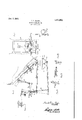
- Fig. 1 is a side view of a control mechanism according to my invention.
- Fig. 2 is a front view of the apparatus illustrated in Fig. 1.
- Figs. 3, 4 and 5 are detail perspective views of parts appearing in Figs. 1 and 2.
- FIG. 1 indicates a treadle member designed for operation by the ball of the foot, member 1 being pivoted on the axis 3. Also pivoted on axis 3 is a treadle member 2 adapted to be operated by the heel of the foot ⁇ the ball of which rests on treads 1. Members 1 and 2 are suitably journalled on axis 3 by brackets 4.- or other suitable means, the adjacent edges of members 1 and 2 embracing a plane which includes the axis 3 and 1 provide a coil spring 5 which serves to normally" hold the members 1 and 2 against the stop bar 6 which lies between the adjacent edges and is fastened to a suitable support.
- the fork 9 is conllected to treadle member 1 at point 12 by means of link 11 and the yoke 9 is connected to treadle member 2 at point 12a by means of link 13.
- Bell crank 7 is connected at its upper end to the throttle valve 19 by means of link 14.
- the axis 10 also has fixed thereto a downwardly extending lever 15 which connects to a link 16, the latter con- 'Tb of hcll crank 7.
- bell crank 7 is connected to a spring 17 which normally holds the upper portion of this crank in a vertical position, the throttle then being closed.
- he bell crank 7 also has two parts in addition to the upper part Ajust mentioned, one of which, 7 ⁇ extends vertically downward when the upper portion of the lever is vertical and the other of which, 7", extends horizontally when the other two parts are vertical.
- the fork 8 has an opening 8 therein through which part 73L of the bell crank extends downwardly when the parts are assembled.
- the fork has also a cross ⁇ piece 8* which normally extends beneath and in contact with the horizontal portion Moreover, the yoke 9 is so assembled on the axis of shaft 10 that it normally lies in contact with and at the right of part 7a, when viewed as in Fig. 1.
- the yoke 9 and lever 15 are fixed to shaft 10, whereas crank 7 and fork 8 may turn freely on the shaft as an axis.
- treadle numbers l and 2 may be mounted to lie normally Hush or level with the Hoor board 20, the dividing plate 6 between treadle members being preferably fixed tothe floor board 20. (fonsequently the foot ofthe operator rests' flat on the accelerator in a natural position and on the level with the floor board Moreover, theA mechanism. is controlled entirely by the foot of the operator and without necessity of his moving his foot from the accelerator4 proper. By merely pushing-with his toe or his heel, he may open merely the throttle alone or both the throttle and the multler cutout.
- a combined mutiler cut-out and throttle control ⁇ comprising two treadle members normally in the same plane, connections whereby one-of said treadle members controls only the throttle ⁇ and ⁇ connections whereby the other yof said .treadle members controls both the throttle and .the mullier cut-out.
Landscapes
- Engineering & Computer Science (AREA)
- Chemical & Material Sciences (AREA)
- Combustion & Propulsion (AREA)
- Transportation (AREA)
- Mechanical Engineering (AREA)
- Control Of Throttle Valves Provided In The Intake System Or In The Exhaust System (AREA)
Description
Jan. 9, 1923.
F. P. COOPER. DUPLEX AccELERAToR.
FILED OCT-1.1921.
un .TMO-L ill,..-
44, mmmamm'.4
Patented ldan. 9, 1923.
FRANK P. COOPER, OF BROOKLYN, NEW YORK.
DUPLEX ACCELERATOR.
Application filed october 1, 1921. Serial No. 504,722.
To all Lo/wm t may concern Be it known that I, FRANK P. COOPER, a citizen of the United States of America, and a resident of the borough of Brooklyn, city, county, and State of New York, have'invented certain new and useful Improvements in Duplex Accelerators, of which the following is a full and complete disclosure.
My invention relates to control apparatus for automobile engines and has as its principal object the provision of means whereby the driver may govern the throttle valve of the engine alone or the throttle valve and the muffler cut-out simultaneously, as desired.
The novel features of my invention are pointed out with particularity in the ap pended claims. The invention itself, however, with further objects and advantages, will best be understood from the following description taken in connection with the accompanying drawing, in which,--
Fig. 1 is a side view of a control mechanism according to my invention.
Fig. 2 is a front view of the apparatus illustrated in Fig. 1.
Figs. 3, 4 and 5 are detail perspective views of parts appearing in Figs. 1 and 2.
In the drawing 1 indicates a treadle member designed for operation by the ball of the foot, member 1 being pivoted on the axis 3. Also pivoted on axis 3 is a treadle member 2 adapted to be operated by the heel of the foot` the ball of which rests on treads 1. Members 1 and 2 are suitably journalled on axis 3 by brackets 4.- or other suitable means, the adjacent edges of members 1 and 2 embracing a plane which includes the axis 3 and 1 provide a coil spring 5 which serves to normally" hold the members 1 and 2 against the stop bar 6 which lies between the adjacent edges and is fastened to a suitable support.
Parallel to the axis 3 l mount a second axis 10 and on axis 10 ll mount, according to my invention, a bell crank 7, a fork 8, a yoke 9, and lever 15. The fork 9 is conllected to treadle member 1 at point 12 by means of link 11 and the yoke 9 is connected to treadle member 2 at point 12a by means of link 13. Bell crank 7 is connected at its upper end to the throttle valve 19 by means of link 14. The axis 10 also has fixed thereto a downwardly extending lever 15 which connects to a link 16, the latter con- 'Tb of hcll crank 7.
necting in turn to the lever 16 of the muiiler cutout. The upper portion of bell crank 7 is connected to a spring 17 which normally holds the upper portion of this crank in a vertical position, the throttle then being closed. l` he bell crank 7 also has two parts in addition to the upper part Ajust mentioned, one of which, 7` extends vertically downward when the upper portion of the lever is vertical and the other of which, 7", extends horizontally when the other two parts are vertical. The fork 8 has an opening 8 therein through which part 73L of the bell crank extends downwardly when the parts are assembled. and the fork has also a cross `piece 8* which normally extends beneath and in contact with the horizontal portion Moreover, the yoke 9 is so assembled on the axis of shaft 10 that it normally lies in contact with and at the right of part 7a, when viewed as in Fig. 1. The yoke 9 and lever 15 are fixed to shaft 10, whereas crank 7 and fork 8 may turn freely on the shaft as an axis.
lf, now, the operator or driver wishes to open the throttle more or less without openingr the muilier cutout he pressesY down with the ball of his foot on treadle member 1` thereby throwing this member into posi tion shown in dot-ted lines in F ig. 1, parts 8 and 11 also being thrown into the dotted lineposition. The fork 8 is thus turned about the axis 10 in the clockwise direction as viewed in Fig. 1, the cross piece 8b being thereby raised and pushed upwardly on the arm 7b of bell crank 7. The crank 7 is thus turned also in the clockwise direction against the spring 17 as indicated in dotted lines in Fig. 1 However, this movement of parts 8 and 7 will not effect yoke 9, since it will be seen from Fig. 1 that a clockwise movement of the bell crank 7 will move part 7a away from yoke 9 without disturbing the yoke. The muflier cutout will thus be undisturbed when the member` 1 is pushed down since -sha-ft 10 and lever 15 will not be operated.
lWhen it is desired to operate both the muffler cutout and the throttle, the operator pushes down on treadle 2 thereby throwing link 13 and yoke 9 in the clockwise direction. as indicated in dotted lines in Fig. 1. The yoke 9 will then push against the part 7 of bell crank i' turning the bell crank clockwise and opening the throttle as above and at the same time yoke 9 will turn the shaft 10 and with it the lever l5, turning this lever also in .clockwise vdirection and throwingflever 15., link 16- and lever 16a. into the dotted line position indicated in Fig. l and thereby opening the mutller cutout 18.
It will be seen, according to my invention, treadle numbers l and 2 may be mounted to lie normally Hush or level with the Hoor board 20, the dividing plate 6 between treadle members being preferably fixed tothe floor board 20. (fonsequently the foot ofthe operator rests' flat on the accelerator in a natural position and on the level with the floor board Moreover, theA mechanism. is controlled entirely by the foot of the operator and without necessity of his moving his foot from the accelerator4 proper. By merely pushing-with his toe or his heel, he may open merely the throttle alone or both the throttle and the multler cutout. lt' is well known that the use ot such.l a cutout has advantages when the automobile is under heavy load as inclimbing a heavy grade, but the inconveniences connected with operating such cutout as formerly-installed and the question ot installation of such prior arrangements have been such as to greatly discourage their use. It will be seen that a muller cutout according to-my invention is readily installed .and operated, at the same time permitting the use ot an accelerator control ot ma-Ximum convenience and simplicity, which. is novel with me and forms a part of, my inventlon.
Having thus described my invention, I claim:
l., ln an automobile in combination, al throttle, a mutller. cut-out, and two treadle members mounted to lie, in Contact with a given foot simultaneously, means whereby the operation of one of said treadle members operates said throttle without said cutout, and means whereby the operation of the renace 4floor board, and a combined throttle and muiiler-cut-out control comprising two individually operable treadlemen'ibers normally in the plane ot said oorboard.
4. In. an automobile, a combined mutiler cut-out and throttle control` comprising two treadle members normally in the same plane, connections whereby one-of said treadle members controls only the throttle` and` connections whereby the other yof said .treadle members controls both the throttle and .the mullier cut-out.
5. ln an automobile in combination, a throttle, a link connected thereto,a vbell crank lever connected.l to Said link, a shaft on which said lever is free to tnrn, a fork mounted on said shaft and also free to turn thereon, said fork operating said bell lever wl'ienturned in one direction but not Iwhen turned lin the other direction, an operator controlled member, a link connecting` said member directly to said fork, yoke iXed to said shaft andadapted tojturn said shaft and bell lever at the Sametime, amuttler cutout. a link connecting said yoke and said cutout, a-second operator controlled member, and a linkconnecting said yoke directly to said second vmentioned member.
FRANK P. COOPER.
Priority Applications (1)
| Application Number | Priority Date | Filing Date | Title |
|---|---|---|---|
| US504722A US1441663A (en) | 1921-10-01 | 1921-10-01 | Duplex accelerator |
Applications Claiming Priority (1)
| Application Number | Priority Date | Filing Date | Title |
|---|---|---|---|
| US504722A US1441663A (en) | 1921-10-01 | 1921-10-01 | Duplex accelerator |
Publications (1)
| Publication Number | Publication Date |
|---|---|
| US1441663A true US1441663A (en) | 1923-01-09 |
Family
ID=24007455
Family Applications (1)
| Application Number | Title | Priority Date | Filing Date |
|---|---|---|---|
| US504722A Expired - Lifetime US1441663A (en) | 1921-10-01 | 1921-10-01 | Duplex accelerator |
Country Status (1)
| Country | Link |
|---|---|
| US (1) | US1441663A (en) |
-
1921
- 1921-10-01 US US504722A patent/US1441663A/en not_active Expired - Lifetime
Similar Documents
| Publication | Publication Date | Title |
|---|---|---|
| US2203777A (en) | Combination accelerator and brake control for vehicles | |
| US1441663A (en) | Duplex accelerator | |
| US3089560A (en) | Control mechanism for motor vehicles | |
| US2020440A (en) | Control mechanism for motor vehicles | |
| US2532861A (en) | Throttle control device | |
| US2489727A (en) | Hand control accelerator for automobiles | |
| US3207276A (en) | Accelerator cancelling pedal | |
| US1907009A (en) | Combined accelerator and brake control | |
| US1897358A (en) | Carburetor control mechanism | |
| US2392086A (en) | Motor vehicle control | |
| US2113974A (en) | Speed controlling mechanism for vehicles | |
| US1549348A (en) | Dual controlling device for motor vehicles | |
| US2590320A (en) | Supplemental throttle controlling device | |
| US1535259A (en) | Foot accelerator | |
| US1375436A (en) | Accelerating device for motor-cars | |
| JPS5939072Y2 (en) | Vehicle speed control device | |
| US2288450A (en) | Accelerator device | |
| US1583959A (en) | Hydrocarbon motor | |
| US2842110A (en) | Carburetor throttle control device | |
| US1595430A (en) | Foot accelerator | |
| US1325018A (en) | Engine control for power-vehicles | |
| US1724596A (en) | Automotive control attachment | |
| US1550920A (en) | Clutch-actuating mechanism | |
| US1397798A (en) | Safety foot-throttle for automobiles | |
| US1841092A (en) | Pedal accelerator control |