US1441237A - Typewriting machine - Google Patents
Typewriting machine Download PDFInfo
- Publication number
- US1441237A US1441237A US355449A US35544920A US1441237A US 1441237 A US1441237 A US 1441237A US 355449 A US355449 A US 355449A US 35544920 A US35544920 A US 35544920A US 1441237 A US1441237 A US 1441237A
- Authority
- US
- United States
- Prior art keywords
- keys
- levers
- key
- bar
- carriage
- Prior art date
- Legal status (The legal status is an assumption and is not a legal conclusion. Google has not performed a legal analysis and makes no representation as to the accuracy of the status listed.)
- Expired - Lifetime
Links
Images


Classifications
-
- B—PERFORMING OPERATIONS; TRANSPORTING
- B41—PRINTING; LINING MACHINES; TYPEWRITERS; STAMPS
- B41J—TYPEWRITERS; SELECTIVE PRINTING MECHANISMS, i.e. MECHANISMS PRINTING OTHERWISE THAN FROM A FORME; CORRECTION OF TYPOGRAPHICAL ERRORS
- B41J25/00—Actions or mechanisms not otherwise provided for
- B41J25/02—Key actions for specified purposes
- B41J25/18—Tabulating
Definitions
- This invention relates to typewriting machines, and more particularly to'tabulating devices for such machines, and is herein disclosed as applied to an Underwood standard typewriting machine.
- the invention as herein disclosed is a decimal tabulating device which is adapted to be actuated by the numeral keys Off the typewriting machine, and is especially adapted to be incorporated in machines of the usual type with the minimum amount of As herein dismay be proare slightly modification or special work.
- the connecting devices may be in the form of hooks adapted to engage studs on the numeral key levers, one book being pro vided for each tabulating stop and corresponding numeral key.
- the hooks may be normally disconnected from the studs and may be swung into engagement withthe studs by a bar which extends across the bank of keys and lies between the numeral bank and the next bank below, thus being out of the way and yet enabling the mechanism to he compact.
- connections may be such that the usual numeral key levers, which print when depressed, are not carried down to the same extent when connected to actuate the decimal stops, with the result that printing is avoid- I key levers may be effective by actuationot a conveniently placed key, which is automatically returned to ineffective position when,
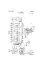
- p Figure 1 is a diagrammatic sectional side view or an Underwood standard typewr tmg machine, showing the present invention as applied thereto, the machine being in normal condition :tor typewritingp Flgure 2 is diagrammatlc side view,
- Figure 3 is a plan view of a numeral key
- Figure is a plan view of the bank of numeral keys showing the concealed tabulatinglegends on the keys.
- Figure 5 is a fragmentary front view, with many parts omitted. showing the numeral keys and some of the tahulating connections.
- Figure 6 a sectional side view of the key seen in Figure 3.
- Figure 7 is a view on a smaller scale, simi lar to Figure 3, but showing the key top rotated to display one tabulating legend and conceal the numeral. 5
- Figures is a fragmentary side view, showing the connecting key depressed to connect the numeral keys to the tabulating devices.
- the tabulatin r mechanism may be made effective by depressing a linger-piece or connecting key which is pivoted by a shouldered screw 26 on a bracket 27, held by screws 28 to the frame of the typewriter inside of a side member 29 at the end of the keyboard.
- a cam 30 on it rides down upon a universal bar or bail 31 which is mounted in arms 32, vpivoted to shouldered screws 33 each fast in one of the sides 29.
- each book is provided with jaws 42, whiclu at the depression of the connecting key are adapted to extend over and em brace a stud 4:25 on its numeral key lever 12, so that the depression of the numeral key will carry down the tabulating;- lever 36 to quake its stop 38 effective.
- a carriage re lease device which may be much of the usual sort and includes a short universal. bar 44 overlying heels 45 on the counter-stops 38:
- connections for lifting the rack bar 20 include a. roll 4-6 on the front end ota, lever 47 pivoted intermediate its ends and connected by a link 1th to the rock arm l9, fast to the shaft 50, which latter fast tothe universal bar i l.
- the roll ",6 when raised runs on the usual tlat margin o i the rack bar 20.
- any tabnlating lever 36 it pivoted at the usual point, nearly inte.'- mediate its ends will raise its counter-stop 38 to the proper position determined. by the usual arresting bar 51 even though the numeral key actuating it is only depressed far enough to raise its type-bar lat to the Figure F or limiting the travel of the counterstops 215 there may be provided notches 52 of much the usual length thus answering the purpose just described.
- each hook is provided with a wire spring 53 which is coiled aroun zl a washer 53, interposed between each hook 3i and its lever 36, and normally throws its hook forwardly to the Figure 1 position against the bar 31.
- the arm 32 which carries the bar 3.1. may be provided with a tail which is adapted to engage a pin 59 fixed in the adjacent side frame 29., it being so located that it arrests the bar 31 with the jaws e2 fully engaged with the studs 42h and yet not creatinsr rious triction of the bar 31 on the hooks ill.
- Each numeral key 11 above referred to is preferably provided with a special body 62 and a top (l3, so that the top may be rotated to display the mimeral printed by the key, or the decimal place at which the key will arrest the carriage when operated in either of two systems of pointing o'tl numbers.
- the bodies 62 are made fast to the key levers 12 in any suitable manner, and the rotatable tops 63 include annular rings M having; lugs (35 which are aih pted to be turned under the bodies; The i numerals and tabulatingr data ori-1n 5; the legends tor the keys may be printed upon the (03s oi? the bodies 62 and show bencaih the glass (36.
- the glass. and fast to the ring may be a shield (5'7, which covers levers extendng 3 0 one of three denr ions 3'0, so ,.o hold the cover 6'? to dis 'ilay one of the three lcgeinls.
- the numeral keys ii are steadied against side-wise; movement by the usual con 1h T1
- the lit oi the hooks 3% on their screw pivots and washers 52-3 is close enough to ensuretheir proper co-eperatioi'i with the nu- 'meral he though the'studs are short enonghto clear" the adjacent v 1 levers 12 and studs til, even i he nun'ieral type usual up per and lower bars fnay incinr case types, and the kev-heads may bearjcoratspondmg upper and"lower-case designa- "trons.
- Variations may he resorted to within the ,scope of the invention, and portions of the improvements may be ,used without others.
- tahulator-levers for operating said counter stops, typewriter character-keys, a universal pix ' fieratedby depression of saidfcherad but only late in theirdepression, tor said levers intermediate their ends, so that thelevers extend forward bcneath the keys, means for connecting the levers to the keys at will, and means :ior limiting .the throw oi: the counter-stops to innit the tabulating throw oi the keys to an amount insutlii'cient to operatethe' universal bar.
- the combi: nation with a traveling carriage and typewriter character-keys arranged in banks, of a column-stop for the carriage, counterstops, devices adjacent said keys for connectingthe counter-stops to the keys of one bank, levers for said character-keys, and a bar universal to said devices and lying above the levers but below the keys, and between the banks. adapted to be swung; to make the] devices effective.
- a typewriting machine in a typewriting machine, the combination with a traveling carriage and a numeral-printing key, of a column-stop on the carriage, a counter-stop, a lever'tor opera tion with a traveling carriage'and type I i a column-stop tor the carriage, counterstops, devices adyacent said keys for connecting; the counter-stops to the keys of one bank, levers for sa d character-keys, a bar universal to said devices and lying above the levers but below the keys, and between v the banks and adapted to be swung forward to make the devices effective, and means ⁇ or limiting the rearward movement of the bar.
- a typewr' ing machine having keys
- a traveling carriage and typewriter character-keys arranged in banks, of a column-stop for the carriage, counterstops, devices adjacent said keys for con necting the counter-stops to the keys of one bank, levers for said character-keys, a bar universal to said devices and lying above the levers, but below the keys, and between the banks, adapted to be swung to make the devices effective, a frame on which said carriage travels, a side of said frame extending past the banks of keys, a key pivoted on said side, and a cam connected to said key to operate said bar.
Description
Jain. 9, 1923. 1,441,237
C. T. MILLER JR.
TYPEWRITLNG MACHINE. FILED JAN. 31 1920 3 SHEETS'SHEET 'l Jan. 9, 11923. 1,441,237
0. T. MILLER, JR.
TYPEWRI TING MACHINE. FILED JAN. 31. 1920.
3 SHEETS'SHEET 2 Jan. 9, 1923.
3 SHEETS-SHEET 3 C. T. MILLER. JR. TYF'EWRITING MACHINE FILED JAN. 31. 1920.
Patented Jan 9, 1923.
as v
cps e CHARLES T. MILLER, 2TB", OF BROOKLYN, NEW] YORK, ASSIGNOR TO UNDERWOOD TYPEWRITEB CGMPANY, 03F NEVJ YORK. N. 55., A CORPORATION OF DELAWARE.
ryrnwnirme MACHINE.
Application filed Januaiy 31, 1920. Serial No. 355,449.
To all whom if: may concern:
Be it known that I, CHARL S T. MILLER,
J12, a citizen of the United States, residing in Brooklyn Borough, in the county of Kings, city and Stateot New York, have invented certain new and useful Improvements in 'lypewriting Machines, of which the following is a specification.
This invention relates to typewriting machines, and more particularly to'tabulating devices for such machines, and is herein disclosed as applied to an Underwood standard typewriting machine.
The invention as herein disclosed is a decimal tabulating device which is adapted to be actuated by the numeral keys Off the typewriting machine, and is especially adapted to be incorporated in machines of the usual type with the minimum amount of As herein dismay be proare slightly modification or special work. closed, the usual decimal stops vided with key levers which shorter than the usual levers, so that said levers, instead of extending to the front of the machine, may terminate substantially beneath the front of the numeral key levers, and are connectible to the latter by normally ineffective connecting devices.
The connecting devices may be in the form of hooks adapted to engage studs on the numeral key levers, one book being pro vided for each tabulating stop and corresponding numeral key. The hooks may be normally disconnected from the studs and may be swung into engagement withthe studs by a bar which extends across the bank of keys and lies between the numeral bank and the next bank below, thus being out of the way and yet enabling the mechanism to he compact.
The connections may be such that the usual numeral key levers, which print when depressed, are not carried down to the same extent when connected to actuate the decimal stops, with the result that printing is avoid- I key levers may be effective by actuationot a conveniently placed key, which is automatically returned to ineffective position when,
released.
Other features and advantages will hereinafter appear.
In the accompanying drawings, pFigure 1 is a diagrammatic sectional side view or an Underwood standard typewr tmg machine, showing the present invention as applied thereto, the machine being in normal condition :tor typewritingp Flgure 2 is diagrammatlc side view,
showingthe position of a numeral key and its associated parts'when actuated to make a tabulating stop efiectlve.
Figure 3 is a plan view of a numeral key,
showing the numeral legend displayed by the rotatable top, and showing the concealed tabulating' legends through the top.
Figure is a plan view of the bank of numeral keys showing the concealed tabulatinglegends on the keys.
Figure 5 is a fragmentary front view, with many parts omitted. showing the numeral keys and some of the tahulating connections.
Figure 6 a sectional side view of the key seen in Figure 3.
Figure 7 is a view on a smaller scale, simi lar to Figure 3, but showing the key top rotated to display one tabulating legend and conceal the numeral. 5
Figures is a fragmentary side view, showing the connecting key depressed to connect the numeral keys to the tabulating devices.
In the Underwood standard typewriting' machine, alphabet keys 10 and numeral keys 11, when depressed, carry down'key levers 12, rocking sub-levers 13 to carry type bars 14 upwardly and rearwardly, so that types 15 thereon print against the "front side of the platen '16, journaled on a carriage 17. Whenever a numeral key 11 or alphabet key 10 is depressed, it feeds the carriage 17 along the distance otone letter space when released, and. tort-his purpose each type-bar 14: is provided with a heel 18 which actuates a segmental universal bar 19, as the types 15 approach the platen. This actuates" the usual escapement device, and permits the usual spring barrel 17 to draw the carriage 17 along the distance of a letter space,the carriage for this purpose being provided with a pivoted rack bar 20, which meshes witb'apinion 21 connected to the escapement wheel, When a key 10 or 11 is released, it returns to normal position under the influenceof its returning spring 22. The carriage 17 travels in the manner described on a" front rail 23 and. arear rail 24:.
When it is desired to bring the carriage 17 rapidly to a more or less distant letter space in its travel, the tabulatin r mechanism may be made effective by depressing a linger-piece or connecting key which is pivoted by a shouldered screw 26 on a bracket 27, held by screws 28 to the frame of the typewriter inside of a side member 29 at the end of the keyboard. \Vhen the key is depressed, a cam 30 on it rides down upon a universal bar or bail 31 which is mounted in arms 32, vpivoted to shouldered screws 33 each fast in one of the sides 29.
As the cam 530 descends it rocks the bar 31 riuirwardly, swinging he connecting books 34 rearwardly,because it bears against the front sides of said hooks. llach hook 3% is pivoted by a shouldered screw 35 upon the front end of a decimal-key lever 36 pivoted intermediate its ends at 37, and adapted to lift its one of an array of counterstops 38 into the path ot a column-stop 39. adjustably mounted on a rack bar 4-0. fast to the usual brackets ti on the typewriter carriage. To enable any hook 2-34 to carry down its key lever 36 in the manner described, each book is provided with jaws 42, whiclu at the depression of the connecting key are adapted to extend over and em brace a stud 4:25 on its numeral key lever 12, so that the depression of the numeral key will carry down the tabulating;- lever 36 to quake its stop 38 effective.
In order to release the carriage from the pinion 21 to enable it to travel until it is arrested at the proper space by a oohu-nnstop 39, when the latter strikes the counter stop 38, there is provided a carriage re lease device which may be much of the usual sort and includes a short universal. bar 44 overlying heels 45 on the counter-stops 38:
said universal bar, when actuated, adapted to lift the rack bar 20 clear of the pinion 21 and allow the spring barrel 1'? to draw the carriage to the left until arrested by the column-stop 39 striking the raised counterstop The connections for lifting the rack bar 20 include a. roll 4-6 on the front end ota, lever 47 pivoted intermediate its ends and connected by a link 1th to the rock arm l9, fast to the shaft 50, which latter fast tothe universal bar i l. The roll ",6 when raised runs on the usual tlat margin o i the rack bar 20. Y
It is found that any tabnlating lever 36, it pivoted at the usual point, nearly inte.'- mediate its ends will raise its counter-stop 38 to the proper position determined. by the usual arresting bar 51 even though the numeral key actuating it is only depressed far enough to raise its type-bar lat to the Figure F or limiting the travel of the counterstops 215 there may be provided notches 52 of much the usual length thus answering the purpose just described. in order to norinally keep the hooks 23 i; clear of the numeral keys and keylevers, each hook is provided with a wire spring 53 which is coiled aroun zl a washer 53, interposed between each hook 3i and its lever 36, and normally throws its hook forwardly to the Figure 1 position against the bar 31. in the ineiilcctive position of the latter, The throw of the bar 31 is limited by the end of the cam slot 56 which normally engages the bar 31 since the connecting key is normally held in its uppermost (liigure 1) position, by a returning spring 57 coiledabout its pivot screw 26.
To limit the rearward travel oi. the bar 31, the arm 32, which carries the bar 3.1. may be provided with a tail which is adapted to engage a pin 59 fixed in the adjacent side frame 29., it being so located that it arrests the bar 31 with the jaws e2 fully engaged with the studs 42h and yet not creatinsr rious triction of the bar 31 on the hooks ill. in order to e ive the key the right feel to the t iq'iist the cam 30 adjacent the bo tom 56 is quite steep, but at point 58 becomes a dwell 60 which holds the bar 31 substantially with the tail 58 against the pin lt found that the bar ill may rest against the downwardly sloping portion ('31 ot the key levers 12 ot' the alphabet keys It), and yet bear far enough down on the backs oi the hooks 34- to enable the nunueral ken, ill to fully t epress the hooks without carrying; them beneath the bar 31 and beyond its control,
Each numeral key 11 above referred to, is preferably provided with a special body 62 and a top (l3, so that the top may be rotated to display the mimeral printed by the key, or the decimal place at which the key will arrest the carriage when operated in either of two systems of pointing o'tl numbers. F or this purpose the bodies 62 are made fast to the key levers 12 in any suitable manner, and the rotatable tops 63 include annular rings M having; lugs (35 which are aih pted to be turned under the bodies; The i numerals and tabulatingr data ori-1n 5; the legends tor the keys may be printed upon the (03s oi? the bodies 62 and show bencaih the glass (36. Above the glass. and fast to the ring (5i, may be a shield (5'7, which covers levers extendng 3 0 one of three denr ions 3'0, so ,.o hold the cover 6'? to dis 'ilay one of the three lcgeinls. i The numeral keys ii are steadied against side-wise; movement by the usual con 1h T1,
and, to hold the hooks 8 71: ,npright, there is provided a comb 72th:: the key levers an. The lit oi the hooks 3% on their screw pivots and washers 52-3 is close enough to ensuretheir proper co-eperatioi'i with the nu- 'meral he though the'studs are short enonghto clear" the adjacent v 1 levers 12 and studs til, even i he nun'ieral type usual up per and lower bars fnay incinr case types, and the kev-heads may bearjcoratspondmg upper and"lower-case designa- "trons.
Variations may he resorted to within the ,scope of the invention, and portions of the improvements may be ,used without others.
'l l aving thus described my invention, l claim: j I
V l. In a typewr ting machine thecoinbina- "tion with a travelingcarriage and columnstops thereon at the rear, of counter-stops, tabnlator-leverstor operating sa d counterstops, typewriter character-keys, pivots for said levers intermediate their ends, said io-rwardly beneath the keys to the front of the inachine, and means eX- tending' upwardly between said keys for chine, studs on the front of certain of said key-levers, hooks pivoted on the front ends of said tabulator-levers extending upwardly between said keys and adapted to engage .iid studs, and a key-operated bar universal to said hooks to make them effective at will.
2-. In a typewriting machine, theco1nbination with a traveling carriage and column stops thereon at the rear, of connter stops, tabulator-levers or operating said fcounterstops, typewrit character-keys having keylevers extending to the front of the machine,
studs on thefront of certain of: said key-- levers, hooks on said tabideter-levers adapted to engage said studs, a spring, for each hook, normally tending to hold it ineiiective, and a bar universal to thehooks adapted to make them effective at will.
-i;.- in a typewriting niacl'iine, the (Xllllblflik tion with a traveling carriage and columnstops thereon at the rear, oi counter-stops,
tahulator-levers for operating said counter stops, typewriter character-keys, a universal pix ' fieratedby depression of saidfcherad but only late in theirdepression, tor said levers intermediate their ends, so that thelevers extend forward bcneath the keys, means for connecting the levers to the keys at will, and means :ior limiting .the throw oi: the counter-stops to innit the tabulating throw oi the keys to an amount insutlii'cient to operatethe' universal bar.
In a type 'riting machine, the con'ibination, with a traveling carriage and typewritenkeys, or a colunnrstop on' the car- 'riage, a plurality of counter-stops, type- 01 26113111154,lQYGi'S for said keyspivoted at the rear of the machine and extending to "the tront thereof, step-operating levers e):-
"tendii substantially the seine distance to the front, devices for connecting the front Yet thetwo setsot levers, and ineans for limiting the throw of the counter-stops to limit the throw of the type-keys to an amount insnilicient to enable the types to print their characters but sufficient to completely operate the counter-stops;
6, in a typewriting machine, the combi- ..iter nuineraldzeys, of a coluinn-stop'on the carriage, a plurality of counter-stops,
type Operating levers for said keys, pivoted at" the rear of the. machine, andextending to the front oit the machine, stopoperating levers extending"substantially the same distance to the front, and devices for connecting the front of the two sets of levers, to enahle an incomplete throw of a numeral a: v to completely operate a counter-stop.
in a typewriting machine, the combi: nation with a traveling carriage and typewriter character-keys arranged in banks, of a column-stop for the carriage, counterstops, devices adjacent said keys for connectingthe counter-stops to the keys of one bank, levers for said character-keys, and a bar universal to said devices and lying above the levers but below the keys, and between the banks. adapted to be swung; to make the] devices effective.
8. In a typewriting machine, the coinbinat on with a traveling carriage and typewriter character-luiys arming d in banks. of
'a"column-stop tor the carriage, cemeterstops, devices adjacent said keys fore-0nnecting the counter-stops to the keys of one bank, levers for said character-keys, a bar universal to said devices and lying above the levers but below the l-:e vs,and between the banks, a key operated can) adapted to swing the barto make the devices effective, and a dwell on said cam adapted to hold the bar ei'l' ei we when near the end oi. its
th row. I
l). in a typewriting machine, the combination with a traveling carriage and a numeral-printing key, of a column-stop on the carriage, a counter-stop, a lever'tor opera tion with a traveling carriage'and type I i a column-stop tor the carriage, counterstops, devices adyacent said keys for connecting; the counter-stops to the keys of one bank, levers for sa d character-keys, a bar universal to said devices and lying above the levers but below the keys, and between v the banks and adapted to be swung forward to make the devices effective, and means {or limiting the rearward movement of the bar.
11. In a typewr' ing machine having keys, the combination with a traveling carriage, of decimal-stops at the rear of the machine, levers extending forwardly, hooks pivoted to said levers, studs fixed to said keys and actuated by the operation of said keys, a bar adapted to swing said hooks to engage said keyoperated studs, a sprin for each hook, normally holding it clear of its stud, and a finger-operated cam adapted to move saidbar to make the hooks effective, and comprising a dwell to hold them effective.
ii In a typewriting machine, the combination with a traveling carriage and typewriter character-keys arranged in banks, of a column-stop for the carriage, counterstops, devices adjacent said keys for con necting the counter-stops to the keys of one bank, levers for said character-keys, a bar universal to said devices and lying above the levers, but below the keys, and between the banks, adapted to be swung to make the devices effective, a frame on which said carriage travels, a side of said frame extending past the banks of keys, a key pivoted on said side, and a cam connected to said key to operate said bar.
13. In a typewriting machine, the combi-' nation with a traveling carriage and typewriter character-keys arranged in banks, of a column-stop for the carriage, counterstops, cevices adjacent said keys for connectiii9- the counter-stops to the keys of one bank, levers for said character-keys, a bar universal to said devices and lying above the levers but below the keys, and between the banks, adapted to be swung to make the devices effective, a frame on which said carriage travels, a side of said framevextendpast the banks ot keys, a cam adapted to throw said bar to effective position, an extension of said cam forming a dwell, adapted to retain the bar at effective position, and a spring-returned key for operating the bar.
CHARLES T. MILLER, JR. itnesses Crrnnmnn A. NEWELL, EDITH B. LIBBEY.
Priority Applications (2)
| Application Number | Priority Date | Filing Date | Title |
|---|---|---|---|
| US355449A US1441237A (en) | 1920-01-31 | 1920-01-31 | Typewriting machine |
| US599751A US1557076A (en) | 1920-01-31 | 1922-11-09 | Typewriting machine |
Applications Claiming Priority (1)
| Application Number | Priority Date | Filing Date | Title |
|---|---|---|---|
| US355449A US1441237A (en) | 1920-01-31 | 1920-01-31 | Typewriting machine |
Publications (1)
| Publication Number | Publication Date |
|---|---|
| US1441237A true US1441237A (en) | 1923-01-09 |
Family
ID=23397469
Family Applications (1)
| Application Number | Title | Priority Date | Filing Date |
|---|---|---|---|
| US355449A Expired - Lifetime US1441237A (en) | 1920-01-31 | 1920-01-31 | Typewriting machine |
Country Status (1)
| Country | Link |
|---|---|
| US (1) | US1441237A (en) |
-
1920
- 1920-01-31 US US355449A patent/US1441237A/en not_active Expired - Lifetime
Similar Documents
| Publication | Publication Date | Title |
|---|---|---|
| US1441237A (en) | Typewriting machine | |
| US2160254A (en) | Typewriting machine | |
| US1169739A (en) | Type-writing machine. | |
| US1194587A (en) | Type-writing machine | |
| US1403329A (en) | Typewriting machine | |
| US1417304A (en) | Typewriting machine | |
| US940395A (en) | Tabulating device for type-writers. | |
| US1441049A (en) | Typewriting machine | |
| US1368599A (en) | Typewriting machihfi | |
| US1283348A (en) | Type-writing machine. | |
| US1462886A (en) | Typewriting machine | |
| US1259497A (en) | Combined type-writing and computing machine. | |
| US1463778A (en) | Typewriting machine | |
| US1480613A (en) | Typewriting machine | |
| US1312145A (en) | Type-writing machine | |
| US1286827A (en) | Type-writing machine. | |
| US1339078A (en) | Typewriting-machine | |
| US1406162A (en) | Typewriting machine | |
| US1278874A (en) | Type-writing machine. | |
| US1347197A (en) | Typewriting-machine | |
| US1504198A (en) | Typewriting machine and the elements thereof | |
| US843828A (en) | Type-writing machine. | |
| US1190312A (en) | Type-writing machine. | |
| US1059782A (en) | Type-writing machine. | |
| US1341028A (en) | Typewriting-machine |