US1440641A - Spherical ball-bearing caster - Google Patents
Spherical ball-bearing caster Download PDFInfo
- Publication number
- US1440641A US1440641A US411781A US41178120A US1440641A US 1440641 A US1440641 A US 1440641A US 411781 A US411781 A US 411781A US 41178120 A US41178120 A US 41178120A US 1440641 A US1440641 A US 1440641A
- Authority
- US
- United States
- Prior art keywords
- bulb
- sphere
- chamber
- bearing
- ball
- Prior art date
- Legal status (The legal status is an assumption and is not a legal conclusion. Google has not performed a legal analysis and makes no representation as to the accuracy of the status listed.)
- Expired - Lifetime
Links
- 241000272470 Circus Species 0.000 description 1
- 101100425947 Mus musculus Tnfrsf13b gene Proteins 0.000 description 1
- SYOKIDBDQMKNDQ-XWTIBIIYSA-N vildagliptin Chemical compound C1C(O)(C2)CC(C3)CC1CC32NCC(=O)N1CCC[C@H]1C#N SYOKIDBDQMKNDQ-XWTIBIIYSA-N 0.000 description 1
Images
Classifications
-
- B—PERFORMING OPERATIONS; TRANSPORTING
- B60—VEHICLES IN GENERAL
- B60B—VEHICLE WHEELS; CASTORS; AXLES FOR WHEELS OR CASTORS; INCREASING WHEEL ADHESION
- B60B33/00—Castors in general; Anti-clogging castors
- B60B33/08—Ball castors
Definitions
- the invention relates to an improvement in spherical ball-bearing casters.
- the object oi the inven ion is to produce a sphern cal ball-bearing caster which will enable the sphere to rotate in any direction with cientfreedom so that at no time will the sphere drag upon the surface with which bears. it is especially intended for use in connection with articles of furniture, such for instance as beds, tables, chairs, couches.
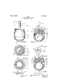
- Fig. 1 is a view in elevation of a caster embodying the invention connected with the leg of a piece of turniture.
- Fig. 2 is a section on line 2-'-2 of Fig. 1.
- 3 is a section on line 33 of Fig. 2.
- a is a plan view of the bulb around the balls for the bearing are to be assembled.
- Fig. 5 is a sectional view showing a modified form of the device embodying the in- I vention.
- Fig.6 is a section on line 6-6 of Fig. 5
- Fig. 7 is a plan view ofthe bulb employed in the modified form of device.
- 1 represents the sphere which is mounted in a suitable holder embodying the invention having a spindle 2 which is adaptedto be engaged with a socket in a leg or foot-piece 3 of the piece of furniture or other article with which the caster is to be employed.
- the head Zl of the holder men'iber Connected with the spindle 2 is the head Zl of the holder men'iber, which has a downwardly extending shell portion 5, said shell portion being; formed with a chamber 6 which is circular in horizontal cross section and has an arched top i. Below the chamber 6 the said shell has a further downwardly extending annu-- lar portion which is of somewhat greater di meter than the diameter of the sphere l.
- a clamping ring 9 Detachably connected with said annular portion 8 is a clamping ring 9 which. is connected with the said annular portion 8 of the shell after the sphere l is introduced within the shell the purpose oi"; said clamp beingto holdthe sphere in place.
- the said clamping ring 9 preferably has a screwthreaded connection 10 with the shell member 8 so that it-can be adjustable as well as 7 detachable'to admit the sphere.
- the said clamping ring 9 is curved inward towards its lower ends, so that the opening at the lower end is of less diameter than the diamv eter of the sphere while the diameter of the '7 5 upper end of the ring is somewhat greater than the diameter of" the sphere.
- Thecontracted lower end of the ring should just barely contact with the sphere throughout its periphery at some distance below' the center of the sphere, so as to holdit from falling-out and from rattling a round.,, butat the same time allowing it freedom of mo-v tion.
- bulb 11. as I have termed it, is secured, 5 centrally within the chamber of the shell 5, said bulb being of any suitable material. It is circular in plan view as shown in Figme a, and is concave on its under side and convex on its upper side in vertical section-9 in all radial directions and is concentric with the sphere 1 as shown in Figure 2. Its periphery is also on'the arc ,ofga circle in vertical section, shown in Figure 2. The diameter of the bulb is sufficiently less than the diameter of the chamber 6 to form a space between the bulb 11 and the wall of the chamber 6, to receive the ball-bearings 12 which entirely surround the bulb.
- a ring 13 is screwed into the shell as shownat 14, said ring 13 having a concaved upper face 15 which follows the curve of the con- The entire downward pressure oi? the art-icle supported by the casters will be vertically downward upon the balls which rest upon the sphere within the space surrounded by the inner periphery 16 of the ring 18.
- This set of bells which sustains the weight are errenged in a circular group on the under side the conceived under surface of the bulb 11, so that the sphere 1 can i (ily roll in any direction-
- hot or ball genie-ht be as n" ny as could be enclosed in the circle whose diameter equa the combined di- (.0 nieter of sin of the bells.
- the bulb 1.1 is formed with e series of shallow grooves 19 crossing one another in various directions on its surface as shown in Figure i, to aid the balls in running to the right and to the left of the spindle 20.
- These grooves should preferably all be curved on the arc of s circle, although they each other at various angles.
- a mount therefor having a chamber above being concave 'ircnhir in horizontal hula suspended in the id bulb being circus d in e end'convex on it of sufficiently less ban the chamber so that there ismed a: continuous ball bearing space erounc the bulb at the top and bottom and sides, the periphery of the bulb being conveii inverticnl section so hnt the bell psssoge'hns continnous curve frojrn the upper to the under side s well as around the periphery, and ball lrieerings filling said the balls on the under side oi?
- a inount therefore having a chamber above the sphere, said chamber being concave in vertical section and circuler'in horizontal SGCUOYL; and having a bulb suspended in the middle of the chamber, said bulb being circular in plan viewnnd concave on its lower face and convex on its upper faceye'nd being of chamber, so that there is formed a continuous bell lJGZIl'lIL space etthe top and bottom and edge oi the bulb and the wells of the ball bearing space being curved in all ports the upper face of the bulb being formed with curved grooves to aid in guiding the circulatory movement of the bells.
Landscapes
- Engineering & Computer Science (AREA)
- Mechanical Engineering (AREA)
- Pivots And Pivotal Connections (AREA)
Description
Jan. 2', 1923.
mo CASTER. 1920.
SPHERI Fl LED Surf. 21
' which sisal-chads sinner srnvnns, or iirnmitocnnr, trains.
SPHEBICAL BALL-BEARING car-ans.
Application filed September .21, 1920Jg$erial No. 411,7531.
To all whomit may concern: 4
it known that I, SIDNEY EVENS, a citizen. of the United States residing at liiillinoc ret, county of l enobscot State or me, have invented a certain new and useul improvement in Spherical Ball-Bearing s, of which the iollowingis a specireference being had therein to the companymg drawings.
The invention relates to an improvement in spherical ball-bearing casters. The object oi the inven ion is to produce a sphern cal ball-bearing caster which will enable the sphere to rotate in any direction with cientfreedom so that at no time will the sphere drag upon the surface with which bears. it is especially intended for use in connection with articles of furniture, such for instance as beds, tables, chairs, couches.
side-boards nianos etc... althou 'h it is well n a l 9 D adapted Ior use in connection with trucks and'with machinery where its peculiar taci ty of turning); in any direction would par tcular'ly adapt it for use.
The invention will be fully understood n the following; description when talren in connection with the accompanying drawings and the novel features thereof will be pointed out and clearly defined inthe claims at the close or" thislspecification.
In the drawings, Fig. 1 is a view in elevation of a caster embodying the invention connected with the leg of a piece of turniture.
Fig. 2 is a section on line 2-'-2 of Fig. 1. 3 is a section on line 33 of Fig. 2. a is a plan view of the bulb around the balls for the bearing are to be assembled.
Fig. 5 is a sectional view showing a modified form of the device embodying the in- I vention.
Fig.6 is a section on line 6-6 of Fig. 5
Fig. 7 is a plan view ofthe bulb employed in the modified form of device.
Referring now to the drawings, 1 represents the sphere which is mounted in a suitable holder embodying the invention having a spindle 2 which is adaptedto be engaged with a socket in a leg or foot-piece 3 of the piece of furniture or other article with which the caster is to be employed. Connected with the spindle 2 is the head Zl of the holder men'iber, which has a downwardly extending shell portion 5, said shell portion being; formed with a chamber 6 which is circular in horizontal cross section and has an arched top i. Below the chamber 6 the said shell has a further downwardly extending annu-- lar portion which is of somewhat greater di meter than the diameter of the sphere l. Detachably connected with said annular portion 8 is a clamping ring 9 which. is connected with the said annular portion 8 of the shell after the sphere l is introduced within the shell the purpose oi"; said clamp beingto holdthe sphere in place. The said clamping ring 9 preferably has a screwthreaded connection 10 with the shell member 8 so that it-can be adjustable as well as 7 detachable'to admit the sphere. The said clamping ring 9 is curved inward towards its lower ends, so that the opening at the lower end is of less diameter than the diamv eter of the sphere while the diameter of the '7 5 upper end of the ring is somewhat greater than the diameter of" the sphere. Thecontracted lower end of the ring should just barely contact with the sphere throughout its periphery at some distance below' the center of the sphere, so as to holdit from falling-out and from rattling a round.,, butat the same time allowing it freedom of mo-v tion. i
bulb 11. as I have termed it, is secured, 5 centrally within the chamber of the shell 5, said bulb being of any suitable material. It is circular in plan view as shown in Figme a, and is concave on its under side and convex on its upper side in vertical section-9 in all radial directions and is concentric with the sphere 1 as shown in Figure 2. Its periphery is also on'the arc ,ofga circle in vertical section, shown in Figure 2. The diameter of the bulb is sufficiently less than the diameter of the chamber 6 to form a space between the bulb 11 and the wall of the chamber 6, to receive the ball-bearings 12 which entirely surround the bulb. In order to close the bottom of the ball-bearing chamber between the sphere and the shell 5, a ring 13 is screwed into the shell as shownat 14, said ring 13 having a concaved upper face 15 which follows the curve of the con- The entire downward pressure oi? the art-icle supported by the casters will be vertically downward upon the balls which rest upon the sphere within the space surrounded by the inner periphery 16 of the ring 18. This set of bells which sustains the weight are errenged in a circular group on the under side the conceived under surface of the bulb 11, so that the sphere 1 can i (ily roll in any direction- As viewen in shows a central sectional there are shown of the wit the sphere, hot or ball genie-ht be as n" ny as could be enclosed in the circle whose diameter equa the combined di- (.0 eineter of sin of the bells.
' The preferred means of securing the head l of the sl l to the bulb shown in Figconsist of El screw-threadedstein 12 e 2 1'4 which crews into the bulb, as shown in Figure iny other suitable form of connection, however, may be employed. Une other form is shown in Figures 5, 6 and 7, in which the bulb is connected with the inner periphery of the shell by four thin pointed pieces 18 which project from the shell 5 radially inward into enge went with the bulb.
Preferably the bulb 1.1 is formed with e series of shallow grooves 19 crossing one another in various directions on its surface as shown in Figure i, to aid the balls in running to the right and to the left of the spindle 20. These grooves should preferably all be curved on the arc of s circle, although they each other at various angles.
What I claim is 1. in combination with a spherical caster;
a mount therefor having a chamber above being concave 'ircnhir in horizontal hula suspended in the id bulb being circus d in e end'convex on it of sufficiently less ban the chamber so that there ismed a: continuous ball bearing space erounc the bulb at the top and bottom and sides, the periphery of the bulb being conveii inverticnl section so hnt the bell psssoge'hns continnous curve frojrn the upper to the under side s well as around the periphery, and ball lrieerings filling said the balls on the under side oi? the the sort c of the sphere, .oe being oi lyr ientheight and underside or the bulb end rec nioven'ient of the bells without any overlnoping oi the balls on one another. ln combination with a spherical caster,
a inount therefore having a chamber above the sphere, said chamber being concave in vertical section and circuler'in horizontal SGCUOYL; and having a bulb suspended in the middle of the chamber, said bulb being circular in plan viewnnd concave on its lower face and convex on its upper faceye'nd being of chamber, so that there is formed a continuous bell lJGZIl'lIL space etthe top and bottom and edge oi the bulb and the wells of the ball bearing space being curved in all ports the upper face of the bulb being formed with curved grooves to aid in guiding the circulatory movement of the bells.
In testimony w iereof l age; my signature.
- SIDNE 1 STEVENS.
sufiiciently'less diameter than the-
Priority Applications (1)
| Application Number | Priority Date | Filing Date | Title |
|---|---|---|---|
| US411781A US1440641A (en) | 1920-09-21 | 1920-09-21 | Spherical ball-bearing caster |
Applications Claiming Priority (1)
| Application Number | Priority Date | Filing Date | Title |
|---|---|---|---|
| US411781A US1440641A (en) | 1920-09-21 | 1920-09-21 | Spherical ball-bearing caster |
Publications (1)
| Publication Number | Publication Date |
|---|---|
| US1440641A true US1440641A (en) | 1923-01-02 |
Family
ID=23630298
Family Applications (1)
| Application Number | Title | Priority Date | Filing Date |
|---|---|---|---|
| US411781A Expired - Lifetime US1440641A (en) | 1920-09-21 | 1920-09-21 | Spherical ball-bearing caster |
Country Status (1)
| Country | Link |
|---|---|
| US (1) | US1440641A (en) |
Cited By (13)
| Publication number | Priority date | Publication date | Assignee | Title |
|---|---|---|---|---|
| US2423711A (en) * | 1945-08-03 | 1947-07-08 | Roy R Knox | Ball-bearing foot for furniture and the like |
| US2779965A (en) * | 1954-04-05 | 1957-02-05 | Smith Corp A O | Ball caster |
| US4108455A (en) * | 1975-12-22 | 1978-08-22 | The Boeing Company | Cargo pallet incorporating retractable ball units |
| USD392875S (en) | 1995-12-26 | 1998-03-31 | Scott Robert L | Rotating ball caster |
| US20050044835A1 (en) * | 2003-02-24 | 2005-03-03 | Viv Engineering Inc. | Hand-pushed mower |
| US20070074372A1 (en) * | 2000-03-03 | 2007-04-05 | Finger Lakes Intellectual Property Llc | Caster system used with wooden or plastic legs for furniture |
| USD668942S1 (en) * | 2012-05-03 | 2012-10-16 | Mcgarry Steven P | Bed frame riser |
| WO2015118493A1 (en) * | 2014-02-06 | 2015-08-13 | Wheel.Me As | A piston device, a rolling mechanism comprising such a piston, a piece of furniture comprising such a piston device or rolling mechanism |
| US20150334917A1 (en) * | 2014-05-23 | 2015-11-26 | Paul Michael Durden | Free Spinning Ball Device |
| US9796213B1 (en) * | 2016-11-04 | 2017-10-24 | Matthew Menard | Multidirectional wheel assembly |
| US10137731B2 (en) * | 2010-11-03 | 2018-11-27 | Douglas G. Willis | Wheel pad |
| USD1034175S1 (en) * | 2022-06-16 | 2024-07-09 | Benyu Casters & Wheels Co., Ltd | Swivel caster |
| USD1064803S1 (en) * | 2021-03-24 | 2025-03-04 | Fujian Secure Medical Technology Co., Ltd | Caster |
-
1920
- 1920-09-21 US US411781A patent/US1440641A/en not_active Expired - Lifetime
Cited By (15)
| Publication number | Priority date | Publication date | Assignee | Title |
|---|---|---|---|---|
| US2423711A (en) * | 1945-08-03 | 1947-07-08 | Roy R Knox | Ball-bearing foot for furniture and the like |
| US2779965A (en) * | 1954-04-05 | 1957-02-05 | Smith Corp A O | Ball caster |
| US4108455A (en) * | 1975-12-22 | 1978-08-22 | The Boeing Company | Cargo pallet incorporating retractable ball units |
| USD392875S (en) | 1995-12-26 | 1998-03-31 | Scott Robert L | Rotating ball caster |
| US7610682B2 (en) * | 2000-03-03 | 2009-11-03 | Finger Lakes Intellectual Property, Llc | Method of affixing a caster on a wooden or plastic furniture leg |
| US20070074372A1 (en) * | 2000-03-03 | 2007-04-05 | Finger Lakes Intellectual Property Llc | Caster system used with wooden or plastic legs for furniture |
| US7222476B2 (en) * | 2003-02-24 | 2007-05-29 | Viv Engineering Inc. | Hand-pushed mower |
| US20050044835A1 (en) * | 2003-02-24 | 2005-03-03 | Viv Engineering Inc. | Hand-pushed mower |
| US10137731B2 (en) * | 2010-11-03 | 2018-11-27 | Douglas G. Willis | Wheel pad |
| USD668942S1 (en) * | 2012-05-03 | 2012-10-16 | Mcgarry Steven P | Bed frame riser |
| WO2015118493A1 (en) * | 2014-02-06 | 2015-08-13 | Wheel.Me As | A piston device, a rolling mechanism comprising such a piston, a piece of furniture comprising such a piston device or rolling mechanism |
| US20150334917A1 (en) * | 2014-05-23 | 2015-11-26 | Paul Michael Durden | Free Spinning Ball Device |
| US9796213B1 (en) * | 2016-11-04 | 2017-10-24 | Matthew Menard | Multidirectional wheel assembly |
| USD1064803S1 (en) * | 2021-03-24 | 2025-03-04 | Fujian Secure Medical Technology Co., Ltd | Caster |
| USD1034175S1 (en) * | 2022-06-16 | 2024-07-09 | Benyu Casters & Wheels Co., Ltd | Swivel caster |
Similar Documents
| Publication | Publication Date | Title |
|---|---|---|
| US1440641A (en) | Spherical ball-bearing caster | |
| US2490879A (en) | Caster | |
| US3127632A (en) | Casters | |
| US1638725A (en) | Glide caster | |
| US2241685A (en) | Wheel | |
| US2495599A (en) | Castor for furniture and the like | |
| US1445747A (en) | Caster | |
| US1358543A (en) | Caster | |
| US1250266A (en) | Toy. | |
| US3235901A (en) | Caster | |
| US1222045A (en) | Caster. | |
| US2920889A (en) | Riding toy | |
| US1610166A (en) | Caster | |
| US545068A (en) | Ball-caster | |
| US1153838A (en) | Ball-bearing caster and the like. | |
| US545789A (en) | Ball caster | |
| US1154448A (en) | Ball-caster. | |
| US1480851A (en) | Caster | |
| US1359506A (en) | Ball-bearing | |
| US616411A (en) | Ball-caster | |
| US2182445A (en) | Caster | |
| US627012A (en) | Fourth to george e | |
| US1139271A (en) | Ball-bearing caster for furniture. | |
| US907649A (en) | Rotatable table. | |
| US2592811A (en) | Ball-bearing assembly |