US1436734A - Process of closing in roller bearings - Google Patents
Process of closing in roller bearings Download PDFInfo
- Publication number
- US1436734A US1436734A US488857A US48885721A US1436734A US 1436734 A US1436734 A US 1436734A US 488857 A US488857 A US 488857A US 48885721 A US48885721 A US 48885721A US 1436734 A US1436734 A US 1436734A
- Authority
- US
- United States
- Prior art keywords
- bridges
- rollers
- cage
- closing
- roller bearings
- Prior art date
- Legal status (The legal status is an assumption and is not a legal conclusion. Google has not performed a legal analysis and makes no representation as to the accuracy of the status listed.)
- Expired - Lifetime
Links
- 238000000034 method Methods 0.000 title description 9
- 238000007493 shaping process Methods 0.000 description 5
- 238000004519 manufacturing process Methods 0.000 description 4
- 238000004080 punching Methods 0.000 description 3
- 238000010008 shearing Methods 0.000 description 3
- 238000003892 spreading Methods 0.000 description 2
- 238000010276 construction Methods 0.000 description 1
- 238000003780 insertion Methods 0.000 description 1
- 230000037431 insertion Effects 0.000 description 1
Images
Classifications
-
- B—PERFORMING OPERATIONS; TRANSPORTING
- B21—MECHANICAL METAL-WORKING WITHOUT ESSENTIALLY REMOVING MATERIAL; PUNCHING METAL
- B21K—MAKING FORGED OR PRESSED METAL PRODUCTS, e.g. HORSE-SHOES, RIVETS, BOLTS OR WHEELS
- B21K1/00—Making machine elements
- B21K1/04—Making machine elements ball-races or sliding bearing races
-
- F—MECHANICAL ENGINEERING; LIGHTING; HEATING; WEAPONS; BLASTING
- F16—ENGINEERING ELEMENTS AND UNITS; GENERAL MEASURES FOR PRODUCING AND MAINTAINING EFFECTIVE FUNCTIONING OF MACHINES OR INSTALLATIONS; THERMAL INSULATION IN GENERAL
- F16C—SHAFTS; FLEXIBLE SHAFTS; ELEMENTS OR CRANKSHAFT MECHANISMS; ROTARY BODIES OTHER THAN GEARING ELEMENTS; BEARINGS
- F16C19/00—Bearings with rolling contact, for exclusively rotary movement
- F16C19/22—Bearings with rolling contact, for exclusively rotary movement with bearing rollers essentially of the same size in one or more circular rows, e.g. needle bearings
- F16C19/34—Bearings with rolling contact, for exclusively rotary movement with bearing rollers essentially of the same size in one or more circular rows, e.g. needle bearings for both radial and axial load
- F16C19/36—Bearings with rolling contact, for exclusively rotary movement with bearing rollers essentially of the same size in one or more circular rows, e.g. needle bearings for both radial and axial load with a single row of rollers
- F16C19/364—Bearings with rolling contact, for exclusively rotary movement with bearing rollers essentially of the same size in one or more circular rows, e.g. needle bearings for both radial and axial load with a single row of rollers with tapered rollers, i.e. rollers having essentially the shape of a truncated cone
-
- F—MECHANICAL ENGINEERING; LIGHTING; HEATING; WEAPONS; BLASTING
- F16—ENGINEERING ELEMENTS AND UNITS; GENERAL MEASURES FOR PRODUCING AND MAINTAINING EFFECTIVE FUNCTIONING OF MACHINES OR INSTALLATIONS; THERMAL INSULATION IN GENERAL
- F16C—SHAFTS; FLEXIBLE SHAFTS; ELEMENTS OR CRANKSHAFT MECHANISMS; ROTARY BODIES OTHER THAN GEARING ELEMENTS; BEARINGS
- F16C33/00—Parts of bearings; Special methods for making bearings or parts thereof
- F16C33/30—Parts of ball or roller bearings
- F16C33/46—Cages for rollers or needles
- F16C33/54—Cages for rollers or needles made from wire, strips, or sheet metal
- F16C33/542—Cages for rollers or needles made from wire, strips, or sheet metal made from sheet metal
- F16C33/543—Cages for rollers or needles made from wire, strips, or sheet metal made from sheet metal from a single part
-
- F—MECHANICAL ENGINEERING; LIGHTING; HEATING; WEAPONS; BLASTING
- F16—ENGINEERING ELEMENTS AND UNITS; GENERAL MEASURES FOR PRODUCING AND MAINTAINING EFFECTIVE FUNCTIONING OF MACHINES OR INSTALLATIONS; THERMAL INSULATION IN GENERAL
- F16C—SHAFTS; FLEXIBLE SHAFTS; ELEMENTS OR CRANKSHAFT MECHANISMS; ROTARY BODIES OTHER THAN GEARING ELEMENTS; BEARINGS
- F16C43/00—Assembling bearings
- F16C43/04—Assembling rolling-contact bearings
- F16C43/06—Placing rolling bodies in cages or bearings
- F16C43/08—Placing rolling bodies in cages or bearings by deforming the cages or the races
- F16C43/083—Placing rolling bodies in cages or bearings by deforming the cages or the races by plastic deformation of the cage
-
- Y—GENERAL TAGGING OF NEW TECHNOLOGICAL DEVELOPMENTS; GENERAL TAGGING OF CROSS-SECTIONAL TECHNOLOGIES SPANNING OVER SEVERAL SECTIONS OF THE IPC; TECHNICAL SUBJECTS COVERED BY FORMER USPC CROSS-REFERENCE ART COLLECTIONS [XRACs] AND DIGESTS
- Y10—TECHNICAL SUBJECTS COVERED BY FORMER USPC
- Y10T—TECHNICAL SUBJECTS COVERED BY FORMER US CLASSIFICATION
- Y10T29/00—Metal working
- Y10T29/49—Method of mechanical manufacture
- Y10T29/49636—Process for making bearing or component thereof
- Y10T29/49643—Rotary bearing
- Y10T29/49679—Anti-friction bearing or component thereof
- Y10T29/49686—Assembling of cage and rolling anti-friction members
- Y10T29/49687—Assembling of cage and rolling anti-friction members with cage making
Definitions
- My invention relates to roller bearings and processes of assembling them.
- One of its principal objects is a devise a cage that will accommodate a larger number of rollers than cages of the kindnow commonly used and that will be simple in construction and easy to manufacture.
- Another principal object is to devise a process of assembling rollers that will correct misalinement of the bridges of the cage and that will conform the bridge-wings to the rollers.
- the invention consists principally in the cage hereinafter described and claimed.
- the invention further consists in conforming the wings or marginal portions of the bridges of the cage to the rollers during the assembling operation so as to form pockets for said rollers, and also in correcting any misalinement of the bridges of the cage during such operation.
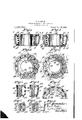
- Fig. 1 is a vertical section through a roller bearing embodying my invention prior to the closing in of the retaining cage;
- Fig. 2 is a top view thereof partly in horizontal section on the line 2-2 in Fig. 1;
- Fig. 3 is a vertical section through the bearing after the closing in of the retaining ca e;
- 4 ig. 4 is a top view thereof partly in section on the line 4-4 in Fig. 3;
- Fig. 54 is a fragmentary end View of the assembled bearing
- Fig. 6 is a fragmentary section through one side of a roller bearing having a slightly modified form of retaining ca e whose bridges are bowed outwardly longitudinally to permit assembling of the bearing;
- Fig. 7 is a horizontal section thereof on the line 7-7 in Fig. 6;
- Fig. 8 is a view similar to Fig. 6, after the closing in ofthe bridges;
- Fig. 9 is a horizontal section thereof on the line 9 9 in Fig. 8;
- Fig. 10 is a longitudinal section through one of the bridges of the cage shown in Figs. 6 to 9 showing the position of the bridges before and after the closing in operation in dotted lines and in full lines, respectively.
- the cage shown in Figs. 1 to 5 of the drawing comprises annular end members 11 that are connected by longitudinally disposed bridge members 12 integral therewith.
- the vmarginal portions of said'bridges are flanged or provided with wings or flaps 13 which constitute the side walls of the pockets for the rollers 14.
- the processv of assembling the bearing shown in F igs. 1 to 5 is as follows:
- the cage is formed by any suitable method with its annular end members 11 of a diameter suiicient to locate the bridges 12 far enough from the center of the bearing to enable the rib 15 on the smaller end of the inner bearing cone 16 to clear the smaller ends of the rollers; and if the bridges 12 have flaps 13 thereon, the flaps of each bridge are brought comparatively closer together, thus making larger pockets than are desired in the assembled bearing.
- the rollers 14 are then inserted in the pockets of the cage and the ribbed cone or inner bearing member 16 is forced endwise thereof, as shown in Figs. 1 and 2.
- the assembledbearing is ,placed in a die (not shown) which is provided with concave recesses adapted to engage the rollers.
- Radially disposed plungers or formers 17 are arranged in slots provided therefor in the die block. Said plungers are equal in number lto the bridges of the cage and are arranged in alinement therewith.
- the fingers 17 are preferably moved inwardly against the bridges by means of cam surfaces on a rotatable ring (not shown).
- the plungers 17 have oblique ends conforming to the taper of the cage. Said ends of the plungers are straight and are adapted to correct the bowing of the bridges and give the cage a true conical shape.
- the edge portions of the plungers are concave and are adapted to spread theflaps 13 andcause them to conform to the rollers 14.
- the inward movement of the portions of the end members disposed opposite to the bridges forms crimped portions 18.
- the pressure of the plungers also corrects the bowing of the bridges and gives the cage the conical form desired.
- the wings are engaged by the plungers, and if the bridges are askew, the plungers, in forcing their way into the space between the wings, tend to straighten out the bridges and correct their alinement.
- the conical edges of the plungers cause the wings to conform to the rollers.
- the process of assembling the bearing shown i-n Figs. 6 to 10 of the drawing is as follows:
- the end members 11a at both ends of the cage, which is formed in any suitable manner, are of the same diameterbefore and after the closing in operation.
- the bridges 12a are bowed outwardly longitudinally near the smaller end of the cage as shown best in Fig. 10; and, if the bridges are provided with flaps 13a, the flaps of each bridge are preferably brought closer together, thus making larger pockets than are desiredin the assembled bearing.
- the rollers 14 are then inserted in the pockets of the cage and the ribbed cone 16 is forced endwise thereof.
- The' bearing is then placed in a die having radially movable fingers 17a.
- the fingers are then forced inwardly in any suitable manner. This inward movement of the fingers causes their beveled inner edges to bear against all of the bridges simultaneously with a force sufficient to ⁇ straighten out the bridges, and spread the flaps and cause them to conform to the rollers. This engagement of the flaps by the beveled edges of the fingers also tends t0 correct any misalinement of the bridges in the event that said bridges are slightly askew. It is noted that with the above arrangement the closing in operation extends the length of the bridges only; whereas, with the arrangement shown in Figs. 1 to 5, the closing in operation extends the entire length of the cage.
- conical roller bearings which consists in punching, shearing and shaping a conical shell to form a cage with annular end mem bers connected by longitudinally bowed bridges that are spaced apart and have marginal flaps which initially project outwardly, inserting conical rollers in the pockets of said cage and straightening said bridges and correcting misalinement thereof and spreading and shaping the flaps thereof by forcing said bridges nearly to the center line of the rollers and thereby forcing said aps against said rollers.
- roller bearings of the kind comprising an inner bearing member, a plurality of rollers and a retaining cage comprising annular end members connected by a plurality of bridges provided with flaps forming pockets for said rollers, which consists in initially forming said retaining cage of a larger diameter than is desired for the finished bearing with the iiaps of said cage closer together than is desired for the finished bearing, placing the rollers in said pockets, placing said inner bearing member in position between' said rollers, and then forcing the bridges of said cage radially inward a distance sufficient to retain said inner bearing member in position and spreading the flaps apart to conform them to the rollers and to correct misalinement of said bridges.
- conical roller bearings which consists in punching, shearing and shaping a conical shell to form a cage with vannular end membersconnected by longitudinally bowed bridges, inserting conical rollers in the pockets of said cage and forcing said bridges radially inward to straighten them and upset the adjacent portions thereof against the rollers and thereby conform said portions to the curvature of the rollers.
Landscapes
- Engineering & Computer Science (AREA)
- General Engineering & Computer Science (AREA)
- Mechanical Engineering (AREA)
- Rolling Contact Bearings (AREA)
Description
R- S. STOFFER.
PROCESS 0F CLOSING IN ROLLER BEARINGS.
' APPLICATION FILED AuG.I, I92I.
W Patented Nov. 28, 1922. .y a 1% /g A43 lil/4I IIIIIIILW@ ramas Nw.. as, raza.
aan
tti
ROY S. STOFIEER, OF CANTON, OHIO. ASSIGNOR TO THE TIMKEN ROLLER BEARING COMPANY, OF CANTON, OHIO, A CORPORATION OIE OHIO.
PROCESS OF CLOSING IN ROLLER BEARINGS.
Application filed August 1, 1921.
To all whom t may concern.'
Be it known that I, ROY S. STOFFER, a citizen of the United States, and a resident of the city of Canton, in the county of Stark and State of Ohio, have invented a new and useful Improvement in Processes of Closing in Roller Bearings, of which the following is a specification.
My invention relates to roller bearings and processes of assembling them. One of its principal objects is a devise a cage that will accommodate a larger number of rollers than cages of the kindnow commonly used and that will be simple in construction and easy to manufacture. Another principal object is to devise a process of assembling rollers that will correct misalinement of the bridges of the cage and that will conform the bridge-wings to the rollers. The invention consists principally in the cage hereinafter described and claimed. The invention further consists in conforming the wings or marginal portions of the bridges of the cage to the rollers during the assembling operation so as to form pockets for said rollers, and also in correcting any misalinement of the bridges of the cage during such operation.
In the accompanying drawing wherein like symbols refer to like parts wherever they occur, p
Fig. 1 is a vertical section through a roller bearing embodying my invention prior to the closing in of the retaining cage;
Fig. 2 is a top view thereof partly in horizontal section on the line 2-2 in Fig. 1;
Fig. 3 is a vertical section through the bearing after the closing in of the retaining ca e;
4 ig. 4 is a top view thereof partly in section on the line 4-4 in Fig. 3;
Fig. 54 is a fragmentary end View of the assembled bearing;
Fig. 6 is a fragmentary section through one side of a roller bearing having a slightly modified form of retaining ca e whose bridges are bowed outwardly longitudinally to permit assembling of the bearing;
Fig. 7 is a horizontal section thereof on the line 7-7 in Fig. 6;
Fig. 8 is a view similar to Fig. 6, after the closing in ofthe bridges;
Serial No. 488,857.
Fig. 9 is a horizontal section thereof on the line 9 9 in Fig. 8; and
Fig. 10 is a longitudinal section through one of the bridges of the cage shown in Figs. 6 to 9 showing the position of the bridges before and after the closing in operation in dotted lines and in full lines, respectively.
The cage shown in Figs. 1 to 5 of the drawing comprises annular end members 11 that are connected by longitudinally disposed bridge members 12 integral therewith. The vmarginal portions of said'bridges are flanged or provided with wings or flaps 13 which constitute the side walls of the pockets for the rollers 14.
The processv of assembling the bearing shown in F igs. 1 to 5 is as follows: The cage is formed by any suitable method with its annular end members 11 of a diameter suiicient to locate the bridges 12 far enough from the center of the bearing to enable the rib 15 on the smaller end of the inner bearing cone 16 to clear the smaller ends of the rollers; and if the bridges 12 have flaps 13 thereon, the flaps of each bridge are brought comparatively closer together, thus making larger pockets than are desired in the assembled bearing. The rollers 14 are then inserted in the pockets of the cage and the ribbed cone or inner bearing member 16 is forced endwise thereof, as shown in Figs. 1 and 2. The assembledbearing is ,placed in a die (not shown) which is provided with concave recesses adapted to engage the rollers. Radially disposed plungers or formers 17 are arranged in slots provided therefor in the die block. Said plungers are equal in number lto the bridges of the cage and are arranged in alinement therewith. The fingers 17 are preferably moved inwardly against the bridges by means of cam surfaces on a rotatable ring (not shown).
The plungers 17 have oblique ends conforming to the taper of the cage. Said ends of the plungers are straight and are adapted to correct the bowing of the bridges and give the cage a true conical shape. The edge portions of the plungers are concave and are adapted to spread theflaps 13 andcause them to conform to the rollers 14. After the inner bearing member 16 has been placed in position with the rib l5 thereof below the small ends of the rollers, the plungers are caused to move radially against the bridges, which motion causes said bridges, together with the portions of the end members adjacent thereto, to move inwardly and forces the rollers into engagement with that portion of the member 16 between the end ribs thereof, which portion constitutes the roller raceway. The inward movement of the portions of the end members disposed opposite to the bridges forms crimped portions 18. The pressure of the plungers also corrects the bowing of the bridges and gives the cage the conical form desired. The wings are engaged by the plungers, and if the bridges are askew, the plungers, in forcing their way into the space between the wings, tend to straighten out the bridges and correct their alinement. The conical edges of the plungers cause the wings to conform to the rollers.
The process of assembling the bearing shown i-n Figs. 6 to 10 of the drawing is as follows: The end members 11a at both ends of the cage, which is formed in any suitable manner, are of the same diameterbefore and after the closing in operation. In order to permit'the insertion of the-cone 16 between the rollers 14:, the bridges 12a are bowed outwardly longitudinally near the smaller end of the cage as shown best in Fig. 10; and, if the bridges are provided with flaps 13a, the flaps of each bridge are preferably brought closer together, thus making larger pockets than are desiredin the assembled bearing. The rollers 14 are then inserted in the pockets of the cage and the ribbed cone 16 is forced endwise thereof. The' bearing is then placed in a die having radially movable fingers 17a. The fingers are then forced inwardly in any suitable manner. This inward movement of the fingers causes their beveled inner edges to bear against all of the bridges simultaneously with a force sufficient to `straighten out the bridges, and spread the flaps and cause them to conform to the rollers. This engagement of the flaps by the beveled edges of the fingers also tends t0 correct any misalinement of the bridges in the event that said bridges are slightly askew. It is noted that with the above arrangement the closing in operation extends the length of the bridges only; whereas, with the arrangement shown in Figs. 1 to 5, the closing in operation extends the entire length of the cage.
If the bridges have no wings, the pressure of the plungers on them corrects the bowing and causes the marginal portions 4thereof to conform to the rollers.
The hereinbefore described process simplifies the operation of assembling roller bearings, insures the proper alinement of the bridges so that the bearing will run proper1-y, minimizes the ynecessity for scrapping cages because of the bridges being askew and conforms the wings accurately to the rollers.
What I claim is A 1. The improvement in the manufacture of conical roller bearings which consists in punching, shearing and shaping a conical shell to form a cage with annular end members connected by longitudinally bowed bridges that are spaced apart and have marginal flaps which initially project outwardly. inserting conical rollers in the pockets of said cage and straightening said bridges and shaping the flaps thereof by the action of radially movable formers whose ends have a straight middle portion and concave edge portions adapted to press the flaps against the rollers and conform them to the curvature thereof.
2. The improvement in the manufacture of conical roller bearings which consists in punching, shearing and shaping a conical shell to form a cage with annular end mem bers connected by longitudinally bowed bridges that are spaced apart and have marginal flaps which initially project outwardly, inserting conical rollers in the pockets of said cage and straightening said bridges and correcting misalinement thereof and spreading and shaping the flaps thereof by forcing said bridges nearly to the center line of the rollers and thereby forcing said aps against said rollers.
3. The process of assembling roller bearings of the kind comprising an inner bearing member, a plurality of rollers and a retaining cage comprising annular end members connected by a plurality of bridges provided with flaps forming pockets for said rollers, which consists in initially forming said retaining cage of a larger diameter than is desired for the finished bearing with the iiaps of said cage closer together than is desired for the finished bearing, placing the rollers in said pockets, placing said inner bearing member in position between' said rollers, and then forcing the bridges of said cage radially inward a distance sufficient to retain said inner bearing member in position and spreading the flaps apart to conform them to the rollers and to correct misalinement of said bridges.
4. The improvement in the manufacture of conical roller bearings which consists in punching, shearing and shaping a conical shell to form a cage with vannular end membersconnected by longitudinally bowed bridges, inserting conical rollers in the pockets of said cage and forcing said bridges radially inward to straighten them and upset the adjacent portions thereof against the rollers and thereby conform said portions to the curvature of the rollers.
Signed at Canton, Ohio, this 28th day of July, 1921.
ROY S. STOFFER.
Priority Applications (1)
| Application Number | Priority Date | Filing Date | Title |
|---|---|---|---|
| US488857A US1436734A (en) | 1921-08-01 | 1921-08-01 | Process of closing in roller bearings |
Applications Claiming Priority (1)
| Application Number | Priority Date | Filing Date | Title |
|---|---|---|---|
| US488857A US1436734A (en) | 1921-08-01 | 1921-08-01 | Process of closing in roller bearings |
Publications (1)
| Publication Number | Publication Date |
|---|---|
| US1436734A true US1436734A (en) | 1922-11-28 |
Family
ID=23941403
Family Applications (1)
| Application Number | Title | Priority Date | Filing Date |
|---|---|---|---|
| US488857A Expired - Lifetime US1436734A (en) | 1921-08-01 | 1921-08-01 | Process of closing in roller bearings |
Country Status (1)
| Country | Link |
|---|---|
| US (1) | US1436734A (en) |
Cited By (8)
| Publication number | Priority date | Publication date | Assignee | Title |
|---|---|---|---|---|
| DE854606C (en) * | 1939-12-15 | 1952-11-06 | Skf Svenska Kullagerfab Ab | Arrangement for axial ball bearings or axial roller bearings |
| DE969961C (en) * | 1951-08-01 | 1958-08-07 | Kugelfischer G Schaefer & Co | Procedure for the assembly of rolling bodies in storage cages |
| WO2011003391A1 (en) * | 2009-07-10 | 2011-01-13 | Schaeffler Technologies Gmbh & Co. Kg | Cage, rolling bearing having the cage, and method |
| US9909453B2 (en) | 2015-05-19 | 2018-03-06 | General Electric Company | Lubrication system for a turbine engine |
| US10234018B2 (en) | 2015-10-19 | 2019-03-19 | General Electric Company | Planet gearbox with cylindrical roller bearing with under race lube scheme |
| US10415429B2 (en) | 2015-09-25 | 2019-09-17 | General Electric Company | Planet gearbox with cylindrical roller bearing with high density roller packing |
| US10787928B2 (en) | 2015-12-01 | 2020-09-29 | General Electric Company | Casing for use in a turbofan engine and method of scavenging fluid therefrom |
| US12421898B2 (en) | 2022-06-22 | 2025-09-23 | General Electric Company | Gearbox assembly with lubricant extraction volume ratio |
-
1921
- 1921-08-01 US US488857A patent/US1436734A/en not_active Expired - Lifetime
Cited By (9)
| Publication number | Priority date | Publication date | Assignee | Title |
|---|---|---|---|---|
| DE854606C (en) * | 1939-12-15 | 1952-11-06 | Skf Svenska Kullagerfab Ab | Arrangement for axial ball bearings or axial roller bearings |
| DE969961C (en) * | 1951-08-01 | 1958-08-07 | Kugelfischer G Schaefer & Co | Procedure for the assembly of rolling bodies in storage cages |
| WO2011003391A1 (en) * | 2009-07-10 | 2011-01-13 | Schaeffler Technologies Gmbh & Co. Kg | Cage, rolling bearing having the cage, and method |
| US9909453B2 (en) | 2015-05-19 | 2018-03-06 | General Electric Company | Lubrication system for a turbine engine |
| US10823005B2 (en) | 2015-05-19 | 2020-11-03 | General Electric Company | Lubrication system for a turbine engine |
| US10415429B2 (en) | 2015-09-25 | 2019-09-17 | General Electric Company | Planet gearbox with cylindrical roller bearing with high density roller packing |
| US10234018B2 (en) | 2015-10-19 | 2019-03-19 | General Electric Company | Planet gearbox with cylindrical roller bearing with under race lube scheme |
| US10787928B2 (en) | 2015-12-01 | 2020-09-29 | General Electric Company | Casing for use in a turbofan engine and method of scavenging fluid therefrom |
| US12421898B2 (en) | 2022-06-22 | 2025-09-23 | General Electric Company | Gearbox assembly with lubricant extraction volume ratio |
Similar Documents
| Publication | Publication Date | Title |
|---|---|---|
| US2591160A (en) | Roller bearing and manufacture thereof | |
| US1436734A (en) | Process of closing in roller bearings | |
| US2435839A (en) | Taper roller bearing and cage | |
| US2139833A (en) | Method of forming rims of nonsymmetrical cross-sectional contour | |
| US1625131A (en) | Die | |
| US1966053A (en) | Method of flanging tubular members | |
| CN104854357B (en) | Axial cage for cylindrical rolling bodies | |
| US3797083A (en) | Sheet metal cage production | |
| US4073551A (en) | Rolling type bearing and method for making same | |
| US1870892A (en) | Roller bearing construction | |
| US2122365A (en) | Method of producing sheet metal cages for cylindrical roller bearings | |
| US2897581A (en) | Method of making roller bearings | |
| US1940124A (en) | Cage for antifriction bearings | |
| US1908521A (en) | Method of beading a cylindrical sheet metal shell | |
| US1712222A (en) | Ball-bearing cage | |
| US3295899A (en) | Cage for rolling bearings | |
| US1736959A (en) | Method of assembling bearings | |
| US2042417A (en) | Roller bearing | |
| US3431037A (en) | Retainer lug construction | |
| EP3129171B1 (en) | Method for manufacturing a spinner bottom for a spinner of a household appliance, spinner, and household appliance | |
| US1518731A (en) | Cage for roller bearings | |
| US1444326A (en) | Method of making cages for bearings | |
| US2756484A (en) | Method of making locked-in bearing assembly | |
| US3013327A (en) | Fabrication of anti-friction bearing units | |
| US1481000A (en) | Method of making ball retainers and the like |