US1434603A - Heateb - Google Patents
Heateb Download PDFInfo
- Publication number
- US1434603A US1434603A US1434603DA US1434603A US 1434603 A US1434603 A US 1434603A US 1434603D A US1434603D A US 1434603DA US 1434603 A US1434603 A US 1434603A
- Authority
- US
- United States
- Prior art keywords
- magazine
- damper
- opening
- heater
- draft
- Prior art date
- Legal status (The legal status is an assumption and is not a legal conclusion. Google has not performed a legal analysis and makes no representation as to the accuracy of the status listed.)
- Expired - Lifetime
Links
- 238000002485 combustion reaction Methods 0.000 description 21
- 239000002956 ash Substances 0.000 description 14
- 239000000446 fuel Substances 0.000 description 13
- 239000003245 coal Substances 0.000 description 9
- 235000002918 Fraxinus excelsior Nutrition 0.000 description 4
- 238000010276 construction Methods 0.000 description 4
- 229910001018 Cast iron Inorganic materials 0.000 description 3
- 229910000831 Steel Inorganic materials 0.000 description 2
- 238000009833 condensation Methods 0.000 description 2
- 230000005494 condensation Effects 0.000 description 2
- 239000000779 smoke Substances 0.000 description 2
- 239000010959 steel Substances 0.000 description 2
- 241000239290 Araneae Species 0.000 description 1
- 101150030193 Nanp gene Proteins 0.000 description 1
- 239000003818 cinder Substances 0.000 description 1
- 238000003780 insertion Methods 0.000 description 1
- 230000037431 insertion Effects 0.000 description 1
- 238000007689 inspection Methods 0.000 description 1
- 230000002452 interceptive effect Effects 0.000 description 1
- 230000001535 kindling effect Effects 0.000 description 1
- 239000002184 metal Substances 0.000 description 1
- 229910052751 metal Inorganic materials 0.000 description 1
- 230000000284 resting effect Effects 0.000 description 1
Images

Definitions
- This invention relates more particularly to self-feeding magazine heaters for burning soft coal.
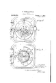
- Figure 1 is a front elevation of a stove or heater embodying the invention
- Fig. 2 is a verticalsection of the heater on the line 22, Figs. 1 and 4:
- Fig. 3 is an enlarged section cm'responding with Fig. 2 of theupper part of the magazine, down-draft pipe, damper and hopper
- Fig. 4 is an enlarged view partly in plan and partly in horizontal sec tion on the line 4-4, Fig. 1
- Fig. 5 is an enlarged horizontal section on the line 55, Fig. 2.
- the stove or heater as shown by the drawings comprises a base and ash pit section 1, to which is bolted or fastened a bottom plate 2, forming therewith a gas-tight rabbet oint.
- the bottom plate 2 is formed or provided with a skirting and with legs 3.
- the base section 1 is formed in the front side with an opening for the insertion and removal of an ash pan 4, and the opening is provided with a door or removable closure 6, forming a tight joint with the base section around the opening.
- the door 6 is fastened to. the base section and held tightly closed by any suitable means, such as hand nuts 7, threaded on studs 8, secured in or to the base section at the sides of the opening, as shown in Figs. 4c and 5.
- a damper 10, formed with triangular or tapering draft-graduating openings 11, is pivotally mounted on the door 6, which is formed with correspondingly shaped draft openings 12, registering with the openings 11.
- the damper is accurately fitted to and is closely held against its seat by a spring 13 on a pivot pin or bolt 14.
- the damper 10 is provided with wings or finger pieces 16, for turning it, and one of them serves as an index in connection with graduation marks or ascale 17 on the door, to indicate the degree of opening of the damper, thus enabling the operator to accurately control and regulate the up-draft of the heater through the ash pit with relation to the down-draft,ashereinafter explained.
- the fire pot is provided with a grate 21, which may be of any suitable construction. As shown, it is of pyramidal form and provided with a central depending stem 22, which is fitted to turn in the central hub of a spider 23, removably fitted to and supported on an inturned flange at the lower end of the fire pot.
- the grate is oscillated or agitated to discharge ashes and cinders accumulating thereon, into the ash pit, by an arm 25, fixed on the lower end of the stem 22 and connected by a link 26 with an arm :27 on the lower end of a vertical shaft 28, rotatably mounted in a bearing on the top wall of the base section 1 at one side of the fire pot, as shown in 2.
- the shaft 28 is provided at itsupper end with a head 29, with which a shaking arm or handle 30 is detachably engaged.
- a heat radiating drum or body section 32 preferably made of sheet steel, is riveted or bolted. to the top of the fire pot 19.
- the drum 32 is riveted or bolted to an annular top plate or section 33 preferably made of cast iron and pro vided at the back side with a smoke pipe or outlet connection 34.
- a downdraft cylinder or pipe 35 preferably made of sheet steel, is bolted or riveted at its upper end to a flanged draft ring 36, detachably bolted or fastened to the annular top plate 33, with which its forms a gas-tight joint.
- the drum 32 forms an annular combustion chamber 37 around the draft pipe 35 above the fire pot 19.
- the pipe At its lower end the pipe is provided with a cast iron collar or refractory mouth piece 38, which is fastened thereto by rivets or bolts 39, having enlarged or extended magazine spacing heads or members at their inner ends.
- the ring 36 is formed with a series of triangular or tapering air inlet openings 41, and adjacent the inner sides of said openings with an inwardly and downwardly projecting spherical annular flange or seat 42.
- a fuel magazine 44 preferably made of cast iron, is rotatably suspended from the spherical annular flange, seat or bearing 42 on the ring 36, within and coaxial with the cylinder or pipe by an outwardly pro jecting spherical annular flange or hearing on a clutch ring 46, to which the magazine is detachably bolted or fastened at its upper end.
- the magazine which is preferably of conicalor tapering shape enlarging downwardly to facilitate the feeding of fuel therefrom to the fire pot. opens at its lower end into the fire pot adjacent the lower end of the mouth piece 38 of the cylinder or pipe 35, with which it forms an annular down-draft flue 47.
- the magazine 44 is held and guided adjacent its lower end coaXially with the surrounding draft cylinder or pipe 35, by the inwardly projecting heads of the rivets or bolts 39.
- An annular damper 49 for'med with triangular or tapering openings 50, corresponding with the openings 44 in the ring 36. is accurately fitted to the top of said. ring so as to turn freely thereon and open and close the air inlet openings into the downdraft flue 47 more or less.
- the damper 49 is formed or provided with funnel or hopper 52, opening into the upper end of the magazine 44, and having an outwardly and downwardlv projectinei skirt and the lower end of the funnel is formed with clutch projections or members 53, which loosely and detachably engage similar clutch projections or members 54 on the ring 46, and hold the damper and funnel coaxial with the draft ring 36 and magazine, thereby affording means for turningthe magazine to detach and loosen the coal contained therein.
- the skirt 55 is provided as shown in Figs. 1 and 4, with handles 57. for adjusting the damper 49 and for turning the magazine 44 to detach. agitate and loosen the coal contained therein.
- An index or pointer 59 on the top plate or section 33. indicates in connection with a scale or graduation marks 60 on. the skirt of the hopper, as shown in Fig. 1., the degree of opening of the damper 49, which is concealed by the skirt, but is movable therewith and thus enables the operator to accurately control and regulate the air supply to the downdraft flue 47 relative to the adjustment of the damper 10 which controls the up-draft through the ash pit and grate.
- the index may be attached to the skirt 55, and the graduation marks placed on the top plate 33, with the same result.
- a removable cover 62 pivotally connected with the top of the funnel or hopper 52 at the back side thereof, as shown in Figs. 2 and 4, and provided with a knob or handle 63, is accurately fitted to the rim of the hopper and normally closes the magazine at the top.
- a lid 65 preferably made of sheet metal and provided with a handle, is hinged at one side in the funnel or hopper 52, as shown in Fig. 2, and forms an auxiliary closure for the magazine.
- the lid is provided with an arm 66, projectng upwardly from its hinge above the top of the hopper, so that when the cover 62 is swun to one side in opening it, it will by engagement with the arm, open the lid, after the initial opening of the cover.
- One or more small openings through the damper 49 admits air into an annular space 71., enclosed by the damper and draft ring 36 around the clutch ring 46 above the flange or hearing 45, and maintains an inward current through the open joints between the clutch members 58 and 54 into the magazine, thereby preventing the outflow from the magazine of gas or oily vapor into said space, and its escape therefrom between, or its condensation on the opposing working faces of the damper and draft ring and of the spherical annular flanges 42 and 45.
- the interfitting spherical faces of the flanges 42 and 45 form a self-adjusting gas tight joint between the draft ring 36 and the magazine 44. which. compensates for any axial misalignment between the annular flange or seat 42 and the lower end of the down-draft pipe 35 and its mouth piece 38,
- the draft ring 36 with the pipe and the magazine 44 may be lifted and removed bodily from the stove through the opening in the top plate 33, the belts or screws fastening the draft ring to the top plate being first removed.
- the grate 21 can be lifted and removed through the opening in the annular top plate 33, the arm 25 having been first disconnected from the stem22 or he magazine at can then be withdrawn and removed from the down-draft pipe through the collar or mouth piece 38, the bolts fastening the n'iagazine to the clutch collar lGhaving been first removed.
- a fire is started with kindling inserted through the magazine a l into the tire pot 19, a thin bed of ashes having preferably been introduced through the magazine and spread over the grate.
- the magazine is then supplied with sufficient coal to start the fire, both dampers 1.0 and 4C9 and the coverfiZ and lid 65 being left open until the coal in the fire pet has been ignited.
- the cover 62 and lid 65 are closed, and the dampers 10 and 19 are adjusted by means of the indexes 16 and 59 and scales 1'? and 60, to control and regulate the up and down drafts according to varying conditions and requirements, the two dampers being set according to corresponding numbers on the scales, to vary both the up and down drafts in the same proportions, for maintaining the desired temperature.
- the graduated. openings of the dampers are and the scales are designed relative to each other. so that when the dampers are set with. the indexes on corresponding numbers of the scales, the
- the grate 21. is shaken from time to time by means of the handle or arm to agitate the fuel bed resting thereon, break up clinkers, and discharge them with. ashes through the openings in and around the into the ash pan .Pis ashes are discharged from the fire. pot, coal is automatically red from the magazine to the upper part of the fuel bed, thereby replenishing the fire. Every time the damper'h is adjusted, the magazine as is turned correspondingly (or if necessary or desirable, it may be turned back and forth when no adjustment of the damper is r quired), thereby agitating the coal con tained therein, preventing it from adhering thereto, and facilitating its feedv therefrom.
- a heater in a heater the combination of a fire pot, a drum forming a; combustion chamber above the fire pot and provided atthe top with an annular bearing and with an air inlet opening, a draft pipe leading from said openlng downwardly lnto the fire pot, a fuel magazine having an annular bearing fitted to turn on the other bearing and to form a close joint therewith and opening at its lower end into the fire.
- pot adjacent thelower end of the draft pipe a damper fitted on the drum and controlling the ad mission of air through said inlet opening into the draft pipe, and a rotatable hopper attached to and movable with the damper and opening into the magazine with which it loosely engages for turning the magazine whenever the damper is adjusted.
- a heater in a heater the combination of a fire pot, a drum enclosing a combustion chamber above the fire p ot and provided at the top with an inwardly projecting spherical annular bearing and with an air inlet opening adjacent the bearing, a down-draft pipe communicating at the upper end with said air inlet opening and opening at its lower end into the fire pot, a fuel magazine pot, a drum forming having an outwardly projecting spherical annular bearing fitted to turn and oscillate about its axis upon the other bearing and to maintain a close joint therewith, the magazine being rotatably suspended by said bearings, a damper movably mounted on the drum and controlling said air inlet opening, and a hopper attached to and movable with the damper and opening into the magazine with which it loosely engages for turning the magazine whenever the damper is adjusted.
- a heater in a heater the combination of a fire pot, a drum enclosing a combustion chamber above the fire pot and having a ring at the top provided with an inwardly projecting annular bearing and with an air inlet opening adjacent the bearing, a downdrai'tpipe suspended from said ring in communication 'with said opening and opening at its lower end into the fire pot, a fuel magazine having an outwardly projecting annular bearing fitted to turn on the other bearing and to maintain a close joint therewith and provided at the upper end with clutch members, a damper movably fitted on said ring and controlling said air inlet opening, and a hopper attached to the damper and provided with clutch members adapted to engage with the clutch members of the magazine for turning the same whenever the damper is ad justed.
- a heater in a heater the combination of a fire pot, a drum enclosing a combustion chamber above the fire potand provided at the top with an inwardly projecting annular bearing and with an air inlet opening, a downdraft pipesuspended from the top of the drum around the air inlet opening therein, a fuel magazine having an outwardly projecting annular bearing fitted to turn upon and form a close joint with the other hearing, a damper movably fitted on the top of the drum and controlling said air inlet opening, and a hopper attached to and movable with the damper and opening into the magazine with which it loosely engages for turning it, an annular space being enclosed between the damper and the magazine above the annular bearings and around the loose joint between the hopper and the magazine.
- a heater In a heater the combination of a fire combustion chamber above the fire pot and provided at the top with an inwardly projecting annular bearing and with an air inlet opening adjacent the bearing, a down-draft pipe suspended from the top of the drum around the air inlet opening therein, a fuel magazine having an outwardly projecting annular bearing fitted to turn on and form a close joint with the other bearing, a damper movably mounted on the top of the drum and controllingthe air inlet opening therein, a rotatable hopper attached to and movable with the damper and opening into the magazine with which it loosely engages for turning it, the hopper being provided with an outwardly projecting skirt damper and with means for turning it with the damper and magazine, and a removable cover for the hopper.
- a heater in a heater the combination with a fire pot and combustion chamber, of a magazine rotatably suspended from the top of the heater and opening at its lower end into the the pot, a down-draft pipe extending from the top of the heater downwardly around the magazine and openinginto the fire pot adjacent the lower end of the magazine, an annular damper rotatably mounted on the top of the heater in loose self-adjusting engagement with the upper end of the magazine and provided with a funnel opening into the magazine, and a removable cover ntting over said funnel.
- a heater In a heater the combination oi an an nular top plate, a down-drattpipe suspended from said plate and provided adjacent its upper end with an air inlet and with a spheri al annular bearing, a magazine spa-Iced from and guided in said down-draft pipe adjacent its lower end and provided adjacent its upper end with spherical annular bearing fitting said and rotatably supported thereon, and a rotatable annular damper controlling the air inlet to said down-draftpipe and adapted to engage with and rotate the magazine.
- a heater in a heater the combination with fire pot and a drum forming a combustion charrber above the fire pot and havii 'an opening in the top plate, of a draft flue extending from the top plate downwardly into the fire potiand having an air intake opening at its upper end, a fuel m zine rotatably mounted in the draft flue, a rotatable hopper loosely and detachably engaging the upper end of the'magazine into which it opens, a damper attached to and rotatable with the hopper and controlling the air intake opening into said flue.
- a down-draft pipe having an ai o rhanging the Lasaeoe inlet opening at its upper end and opening at its lower end adjacent the lower end of the magazine, and an annular damper controlling the inlet opening into the down-dr ft pipe and having a loose rotating connection with the magazine, an annular space being enclosed between the magazine and damper around the loose joint between them and having an air inlet opening to maintain an inward current of air through said space and joint into the magazine.
- a heater the combination with a fire pot and combustion chamber, of a magazine rotatably suspended from the top of the heater and opening at its lower end into the fire pot, a down-draft pipe having an air inlet opening at its upper end and opening at its lower end adjacent the lower end of the magazine, a damper controlling said air inlet opening, a rotatable hopper attached to the damper and having a rotating connection with the magazine, a cover closely fitting the top of the hopper and provided with an air inlet opening, and a lid loosely fitting the hopper between the cover and magazine.
- a heater in a heater the combination with a fire pot and combustion chamber, of a magazine rotatably suspended from the top of the heater within the combustion chamber, a hopper having a rotating connection with the magazine, a clown-draft pipe having an air inlet opening at the upper end and open ing at its lower end adjacent the lower end of the magazine, a damper connected and movable with the magazine and hopper and controlling said air inlet opening, a close fitting cover movably mounted on the hop per, a lid loosely fitting in the hopper between the cover and magazine, and means for automatically opening the lid after the initial opening of the cover.
- a heater In a heater the combination with an ash pit, fire pot provided. with a grate and a combustion chamber, of a magazine rotatably suspended from the top of the heater within the combustion chamber and opening at its lower end into the fire pot, a downdraft pipe having an air inlet opening at its upper end and opening at its lower end adjacent the lower end of the magazine, a damper controlling the inlet opening into the down-draft pipe and having a rotating connection with the magazine, an rip-draft damper controlling the admission of air through the ash pit and grate into the fire pot, and means for adjusting the dampers relative to each other to correspondingly vary the up and down drafts.
- l ash pit a fire pot provided with a grate and a combustion chamber, of a magazine rotatably suspended from the top of the heater within the combustion chamber and opening at its lower end into the fire pot, a down-draft pipe having an air inlet opening at its upper end and opening at its lower end adjacent n a heater the combination with an the lower end of the magazine, a damper having a graduated opening controlling the admission of air into the down-draft pipe, an Lip-draft damper having graduated opening controlling the admission of air through the ash pit and grade into the fire pot, and indexes and scales for adjusting the dampers relative to each other to correspond-c ingly vary the up and down drafts.
Landscapes
- Regulation And Control Of Combustion (AREA)
Description
"R. GAERTNER AND H. KLEIN.
HEATER.
APPLICATION FILED FEB 3, 1922.
Patented Nov. 7, 1922.v
- 2 SHEETS-SHEET l- B. GAERTNER' AND H. KLEIN.
HEATER.
APPLICATION men FEB. a, 1922.
2 SHEETS-SHEET 2.
Patented Nov. 7, 1922.
rrEn srArgs Pa eur cl rics- RICHARD GAERTNER AND HERMAN KLEIN, OF MILWAUKEE, WISCONSIN, ASSIGNORS TO TRIUMPH STOVE AND HEATER COMPANY, OF WA'U'WATOSA, WISCONSIN, A COB- PORATION OF WISCONSIN.
HEATER.
Application filed February 3, 1922. Serial No. 533,767.
To rtZ-J 10/10 In it may. 00 n-cern Be it known that we, RICHARD zlnnTNnn and Hammer KLEIN, citizens of the United States, residing at Milwaukee, in the county of Milwaukee and. State of \Visconsiir. have invented certain new and useful Improvements in Heaters. of which the following is a specification, reference being had to the accompanying drawing, forming a part thereof.
This invention relates more particularly to self-feeding magazine heaters for burning soft coal.
its main objects are to obtain a more perfect comlmstion and regulation of the combustion of the fuel, to facilitate control and regulation of the drafts, to prevent the escape of gas from the heater, to prevent the coal from adhering to and clogging the magazine, to insure the proper feed of the fuel from the magazine into the fire pot, and generally to improve the construction and operation of heaters of this class.
It consists in the construction, arrangement and combination of parts as hereinafter particularly described and pointed out in the claims.
In the accompanying drawings like characters designate the same parts in the several figures.
Figure 1 is a front elevation of a stove or heater embodying the invention; Fig. 2 is a verticalsection of the heater on the line 22, Figs. 1 and 4:; Fig. 3 is an enlarged section cm'responding with Fig. 2 of theupper part of the magazine, down-draft pipe, damper and hopper; Fig. 4 is an enlarged view partly in plan and partly in horizontal sec tion on the line 4-4, Fig. 1; and Fig. 5 is an enlarged horizontal section on the line 55, Fig. 2.
The stove or heater as shown by the drawings, according to the preferred construction thereof, comprises a base and ash pit section 1, to which is bolted or fastened a bottom plate 2, forming therewith a gas-tight rabbet oint. The bottom plate 2 is formed or provided with a skirting and with legs 3. The base section 1 is formed in the front side with an opening for the insertion and removal of an ash pan 4, and the opening is provided with a door or removable closure 6, forming a tight joint with the base section around the opening. The door 6 is fastened to. the base section and held tightly closed by any suitable means, such as hand nuts 7, threaded on studs 8, secured in or to the base section at the sides of the opening, as shown in Figs. 4c and 5.
A damper 10, formed with triangular or tapering draft-graduating openings 11, is pivotally mounted on the door 6, which is formed with correspondingly shaped draft openings 12, registering with the openings 11. The damper is accurately fitted to and is closely held against its seat by a spring 13 on a pivot pin or bolt 14.
The damper 10 is provided with wings or finger pieces 16, for turning it, and one of them serves as an index in connection with graduation marks or ascale 17 on the door, to indicate the degree of opening of the damper, thus enabling the operator to accurately control and regulate the up-draft of the heater through the ash pit with relation to the down-draft,ashereinafter explained.
A fire pot 19, forming a gastight rabbet joint with the base section 1, is bolted or fastened thereto around an opening in the top wall thereof. The fire pot is provided with a grate 21, which may be of any suitable construction. As shown, it is of pyramidal form and provided with a central depending stem 22, which is fitted to turn in the central hub of a spider 23, removably fitted to and supported on an inturned flange at the lower end of the fire pot.
The grate is oscillated or agitated to discharge ashes and cinders accumulating thereon, into the ash pit, by an arm 25, fixed on the lower end of the stem 22 and connected by a link 26 with an arm :27 on the lower end of a vertical shaft 28, rotatably mounted in a bearing on the top wall of the base section 1 at one side of the fire pot, as shown in 2. The shaft 28 is provided at itsupper end with a head 29, with which a shaking arm or handle 30 is detachably engaged.
A heat radiating drum or body section 32, preferably made of sheet steel, is riveted or bolted. to the top of the fire pot 19.
At its upper end the drum 32 is riveted or bolted to an annular top plate or section 33 preferably made of cast iron and pro vided at the back side witha smoke pipe or outlet connection 34.
A downdraft cylinder or pipe 35, preferably made of sheet steel, is bolted or riveted at its upper end to a flanged draft ring 36, detachably bolted or fastened to the annular top plate 33, with which its forms a gas-tight joint.
The drum 32 forms an annular combustion chamber 37 around the draft pipe 35 above the fire pot 19.
At its lower end the pipe is provided with a cast iron collar or refractory mouth piece 38, which is fastened thereto by rivets or bolts 39, having enlarged or extended magazine spacing heads or members at their inner ends.
As shown in Figs. 2 and 4, the ring 36 is formed with a series of triangular or tapering air inlet openings 41, and adjacent the inner sides of said openings with an inwardly and downwardly projecting spherical annular flange or seat 42.
A fuel magazine 44, preferably made of cast iron, is rotatably suspended from the spherical annular flange, seat or bearing 42 on the ring 36, within and coaxial with the cylinder or pipe by an outwardly pro jecting spherical annular flange or hearing on a clutch ring 46, to which the magazine is detachably bolted or fastened at its upper end. The magazine, which is preferably of conicalor tapering shape enlarging downwardly to facilitate the feeding of fuel therefrom to the fire pot. opens at its lower end into the fire pot adjacent the lower end of the mouth piece 38 of the cylinder or pipe 35, with which it forms an annular down-draft flue 47. The magazine 44 is held and guided adjacent its lower end coaXially with the surrounding draft cylinder or pipe 35, by the inwardly projecting heads of the rivets or bolts 39.
An annular damper 49, for'med with triangular or tapering openings 50, corresponding with the openings 44 in the ring 36. is accurately fitted to the top of said. ring so as to turn freely thereon and open and close the air inlet openings into the downdraft flue 47 more or less.
The damper 49 is formed or provided with funnel or hopper 52, opening into the upper end of the magazine 44, and having an outwardly and downwardlv projectinei skirt and the lower end of the funnel is formed with clutch projections or members 53, which loosely and detachably engage similar clutch projections or members 54 on the ring 46, and hold the damper and funnel coaxial with the draft ring 36 and magazine, thereby affording means for turningthe magazine to detach and loosen the coal contained therein. The skirt 55 is provided as shown in Figs. 1 and 4, with handles 57. for adjusting the damper 49 and for turning the magazine 44 to detach. agitate and loosen the coal contained therein.
An index or pointer 59 on the top plate or section 33. indicates in connection with a scale or graduation marks 60 on. the skirt of the hopper, as shown in Fig. 1., the degree of opening of the damper 49, which is concealed by the skirt, but is movable therewith and thus enables the operator to accurately control and regulate the air supply to the downdraft flue 47 relative to the adjustment of the damper 10 which controls the up-draft through the ash pit and grate. Obviously, the index may be attached to the skirt 55, and the graduation marks placed on the top plate 33, with the same result.
A removable cover 62, pivotally connected with the top of the funnel or hopper 52 at the back side thereof, as shown in Figs. 2 and 4, and provided with a knob or handle 63, is accurately fitted to the rim of the hopper and normally closes the magazine at the top. A lid 65, preferably made of sheet metal and provided with a handle, is hinged at one side in the funnel or hopper 52, as shown in Fig. 2, and forms an auxiliary closure for the magazine.
For convenience in charging the magazine with fuel, the lid is provided with an arm 66, projectng upwardly from its hinge above the top of the hopper, so that when the cover 62 is swun to one side in opening it, it will by engagement with the arm, open the lid, after the initial opening of the cover.
A small air inlet opening 68, in the cover 62, admits suflicient air into the hopper and thence around the margin of the, lid 65. which fits loosely in the hopper, to maintain a down-current through the magazine and carry any gas that might otherwise collect therein and in the space between the lid and cover and escape therefrom into the room. downward into the fire pot, in which it will be consumed or from which it will be carried off with the products of combustion throusrh the combustion chamber surrounding the downdraft pipe into the smoke pipe or outlet connection 34.
One or more small openings through the damper 49, admits air into an annular space 71., enclosed by the damper and draft ring 36 around the clutch ring 46 above the flange or hearing 45, and maintains an inward current through the open joints between the clutch members 58 and 54 into the magazine, thereby preventing the outflow from the magazine of gas or oily vapor into said space, and its escape therefrom between, or its condensation on the opposing working faces of the damper and draft ring and of the spherical annular flanges 42 and 45.
The interfitting spherical faces of the flanges 42 and 45 form a self-adjusting gas tight joint between the draft ring 36 and the magazine 44. which. compensates for any axial misalignment between the annular flange or seat 42 and the lower end of the down-draft pipe 35 and its mouth piece 38,
the link 26 from the arm in which the lower end of the magazine is held and guided centrally'by the heads of the bolts or rivets 39, and enables the magazine to be easily turned with the damper inspection, repair and renewal of internal parts of the stove.
The draft ring 36 with the pipe and the magazine 44, may be lifted and removed bodily from the stove through the opening in the top plate 33, the belts or screws fastening the draft ring to the top plate being first removed. After the magazine has been thus removed from the stove with the draft ring 36 and pipe 35,.the grate 21 can be lifted and removed through the opening in the annular top plate 33, the arm 25 having been first disconnected from the stem22 or he magazine at can then be withdrawn and removed from the down-draft pipe through the collar or mouth piece 38, the bolts fastening the n'iagazine to the clutch collar lGhaving been first removed.
In the operationof the stove, a fire is started with kindling inserted through the magazine a l into the tire pot 19, a thin bed of ashes having preferably been introduced through the magazine and spread over the grate. The magazine is then supplied with sufficient coal to start the fire, both dampers 1.0 and 4C9 and the coverfiZ and lid 65 being left open until the coal in the fire pet has been ignited. y
When the coal has been thus ignited. the cover 62 and lid 65 are closed, and the dampers 10 and 19 are adjusted by means of the indexes 16 and 59 and scales 1'? and 60, to control and regulate the up and down drafts according to varying conditions and requirements, the two dampers being set according to corresponding numbers on the scales, to vary both the up and down drafts in the same proportions, for maintaining the desired temperature. The graduated. openings of the dampers are and the scales are designed relative to each other. so that when the dampers are set with. the indexes on corresponding numbers of the scales, the
required proportions of air will be supplied by the up and down drafts, to produce and maintain proper combustion. I
Sutficient air is admitted into the upper part of the magazine through the openings 68 and 70, to prevent the escape of gas therefrominto the room in which the heater is located, and the escape of oily vapor from the magazine into and through the annular space. 71 and its entry between and condensation on the work" faces of the draft ring 36 and damper J. or the i .'orl-:ing'faees of the spherical annular nanp'es and 4. .5, and thereby interfering with the free movement of the damper and magazine.
The grate 21. is shaken from time to time by means of the handle or arm to agitate the fuel bed resting thereon, break up clinkers, and discharge them with. ashes through the openings in and around the into the ash pan .Pis ashes are discharged from the fire. pot, coal is automatically red from the magazine to the upper part of the fuel bed, thereby replenishing the fire. Every time the damper'h is adjusted, the magazine as is turned correspondingly (or if necessary or desirable, it may be turned back and forth when no adjustment of the damper is r quired), thereby agitating the coal con tained therein, preventing it from adhering thereto, and facilitating its feedv therefrom.
constructionand arrangement of parts of the stove or heater may be made without departure from the principle and scope of the invention as defined in the following claims.
This application is in part a substitute for and continuation of our application Serial No. 247,147, filed July 29, 1918.
We claim: I I
1. In a heater the combination of a fire pot, a drum forming a; combustion chamber above the fire pot and provided atthe top with an annular bearing and with an air inlet opening, a draft pipe leading from said openlng downwardly lnto the fire pot, a fuel magazine having an annular bearing fitted to turn on the other bearing and to form a close joint therewith and opening at its lower end into the fire. pot adjacent thelower end of the draft pipe, a damper fitted on the drum and controlling the ad mission of air through said inlet opening into the draft pipe, and a rotatable hopper attached to and movable with the damper and opening into the magazine with which it loosely engages for turning the magazine whenever the damper is adjusted.
2. In a heater the combination of a fire pot, a drum enclosing a combustion chamber above the fire p ot and provided at the top with an inwardly projecting spherical annular bearing and with an air inlet opening adjacent the bearing, a down-draft pipe communicating at the upper end with said air inlet opening and opening at its lower end into the fire pot, a fuel magazine pot, a drum forming having an outwardly projecting spherical annular bearing fitted to turn and oscillate about its axis upon the other bearing and to maintain a close joint therewith, the magazine being rotatably suspended by said bearings, a damper movably mounted on the drum and controlling said air inlet opening, and a hopper attached to and movable with the damper and opening into the magazine with which it loosely engages for turning the magazine whenever the damper is adjusted.
3. In a heater the combination of a fire pot, a drum enclosing a combustion chamber above the fire pot and having a ring at the top provided with an inwardly projecting annular bearing and with an air inlet opening adjacent the bearing, a downdrai'tpipe suspended from said ring in communication 'with said opening and opening at its lower end into the fire pot, a fuel magazine having an outwardly projecting annular bearing fitted to turn on the other bearing and to maintain a close joint therewith and provided at the upper end with clutch members, a damper movably fitted on said ring and controlling said air inlet opening, and a hopper attached to the damper and provided with clutch members adapted to engage with the clutch members of the magazine for turning the same whenever the damper is ad justed. I x
4. In a heater the combination of a fire pot, a drum enclosing a combustion chamber above the fire potand provided at the top with an inwardly projecting annular bearing and with an air inlet opening, a downdraft pipesuspended from the top of the drum around the air inlet opening therein, a fuel magazine having an outwardly projecting annular bearing fitted to turn upon and form a close joint with the other hearing, a damper movably fitted on the top of the drum and controlling said air inlet opening, and a hopper attached to and movable with the damper and opening into the magazine with which it loosely engages for turning it, an annular space being enclosed between the damper and the magazine above the annular bearings and around the loose joint between the hopper and the magazine.
In a heater the combination of a fire combustion chamber above the fire pot and provided at the top with an inwardly projecting annular bearing and with an air inlet opening adjacent the bearing, a down-draft pipe suspended from the top of the drum around the air inlet opening therein, a fuel magazine having an outwardly projecting annular bearing fitted to turn on and form a close joint with the other bearing, a damper movably mounted on the top of the drum and controllingthe air inlet opening therein, a rotatable hopper attached to and movable with the damper and opening into the magazine with which it loosely engages for turning it, the hopper being provided with an outwardly projecting skirt damper and with means for turning it with the damper and magazine, and a removable cover for the hopper.
6. in a heater the combination with a fire pot and combustion chamber, of a magazine rotatably suspended by a self-adjusting spherical bearing from the top of the heater and opening at the lower end into the fire pet, and a down-draft pipe suspended from top or the heater around the magazine and provided adjacent to its lower end with a ring which is spaced from the magazine and in which the lower end of the magazine is rotatably guided.
7. In a heater the combination with a fire pot and combustion chamber, of a magazine rotatably suspended from the top of the heater and opening at its lower end into the the pot, a down-draft pipe extending from the top of the heater downwardly around the magazine and openinginto the fire pot adjacent the lower end of the magazine, an annular damper rotatably mounted on the top of the heater in loose self-adjusting engagement with the upper end of the magazine and provided with a funnel opening into the magazine, and a removable cover ntting over said funnel.
8, In a heater the combination oi an an nular top plate, a down-drattpipe suspended from said plate and provided adjacent its upper end with an air inlet and with a spheri al annular bearing, a magazine spa-Iced from and guided in said down-draft pipe adjacent its lower end and provided adjacent its upper end with spherical annular bearing fitting said and rotatably supported thereon, and a rotatable annular damper controlling the air inlet to said down-draftpipe and adapted to engage with and rotate the magazine.
9. In a heater the combination with fire pot and a drum forming a combustion charrber above the fire pot and havii 'an opening in the top plate, of a draft flue extending from the top plate downwardly into the fire potiand having an air intake opening at its upper end, a fuel m zine rotatably mounted in the draft flue, a rotatable hopper loosely and detachably engaging the upper end of the'magazine into which it opens, a damper attached to and rotatable with the hopper and controlling the air intake opening into said flue.
10. In a heater the combination with a pot and combustion chamber, of a magazine rotatably suspended from the top of the heater and opening at its lower end into the fire pot, a down-draft pipe having an ai o rhanging the Lasaeoe inlet opening at its upper end and opening at its lower end adjacent the lower end of the magazine, and an annular damper controlling the inlet opening into the down-dr ft pipe and having a loose rotating connection with the magazine, an annular space being enclosed between the magazine and damper around the loose joint between them and having an air inlet opening to maintain an inward current of air through said space and joint into the magazine.
11. In a heater the combination with a lire pot and combustion chamber, of a magazine rotatably suspended from the top of the heater and opening at its lower end into the fire pot, a down-draft pipe having an air inlet opening at its upper end and opening at its lower end adjacent the lower end of the magazine, a damper controlling said air inlet opening, a rotatable hopper attached to the damper and having a rotating connection with the magazine, a cover closely fitting the top of the hopper and provided with an air inlet opening, and a lid loosely fitting the hopper between the cover and magazine.
12. In a heater the combination with a fire pot and combustion chamber, of a magazine rotatably suspended from the top of the heater within the combustion chamber, a hopper having a rotating connection with the magazine, a clown-draft pipe having an air inlet opening at the upper end and open ing at its lower end adjacent the lower end of the magazine, a damper connected and movable with the magazine and hopper and controlling said air inlet opening, a close fitting cover movably mounted on the hop per, a lid loosely fitting in the hopper between the cover and magazine, and means for automatically opening the lid after the initial opening of the cover.
13. In a heater the combination with an ash pit, fire pot provided. with a grate and a combustion chamber, of a magazine rotatably suspended from the top of the heater within the combustion chamber and opening at its lower end into the fire pot, a downdraft pipe having an air inlet opening at its upper end and opening at its lower end adjacent the lower end of the magazine, a damper controlling the inlet opening into the down-draft pipe and having a rotating connection with the magazine, an rip-draft damper controlling the admission of air through the ash pit and grate into the fire pot, and means for adjusting the dampers relative to each other to correspondingly vary the up and down drafts.
14:. l ash pit, a fire pot provided with a grate and a combustion chamber, of a magazine rotatably suspended from the top of the heater within the combustion chamber and opening at its lower end into the fire pot, a down-draft pipe having an air inlet opening at its upper end and opening at its lower end adjacent n a heater the combination with an the lower end of the magazine, a damper having a graduated opening controlling the admission of air into the down-draft pipe, an Lip-draft damper having graduated opening controlling the admission of air through the ash pit and grade into the fire pot, and indexes and scales for adjusting the dampers relative to each other to correspond-c ingly vary the up and down drafts.
In witness whereof we hereto afiix our signatures.
RICHARD GAERTNER. HERMAN KLEIN.
Publications (1)
| Publication Number | Publication Date |
|---|---|
| US1434603A true US1434603A (en) | 1922-11-07 |
Family
ID=3402837
Family Applications (1)
| Application Number | Title | Priority Date | Filing Date |
|---|---|---|---|
| US1434603D Expired - Lifetime US1434603A (en) | Heateb |
Country Status (1)
| Country | Link |
|---|---|
| US (1) | US1434603A (en) |
-
0
- US US1434603D patent/US1434603A/en not_active Expired - Lifetime
Similar Documents
| Publication | Publication Date | Title |
|---|---|---|
| US659971A (en) | Heating-stove. | |
| US1434603A (en) | Heateb | |
| US1832223A (en) | Sawdust burner | |
| US2246809A (en) | Oil burner | |
| US2104127A (en) | Air deaft and smoke consumer | |
| US524248A (en) | Heating-stove | |
| US2065264A (en) | Burner | |
| US1441531A (en) | William thomas ckoslen | |
| US2075485A (en) | Heating structure | |
| US2020026A (en) | Automatic underfeed furnace | |
| US2804030A (en) | Incinerator | |
| US438667A (en) | Hot-air furnace | |
| US505631A (en) | Fred l | |
| US1848878A (en) | Steam boiler | |
| GB2177192A (en) | Cooking stove | |
| US2212724A (en) | Stoker furnace or heater | |
| US1341723A (en) | Heating apparatus | |
| US40591A (en) | Improvement in gas-heating apparatus | |
| US1196145A (en) | Stove ob fubbtace | |
| US625417A (en) | Magazine attachment for stoves or furnaces | |
| US1694163A (en) | Smoke box | |
| US1497049A (en) | Brooder stove | |
| US179541A (en) | Improvement in magazine-stoves | |
| US1368701A (en) | Heating-stove | |
| US1301322A (en) | Incinerator. |