US1430808A - Two-way impedance equalizer for transformers - Google Patents
Two-way impedance equalizer for transformers Download PDFInfo
- Publication number
- US1430808A US1430808A US264656A US26465618A US1430808A US 1430808 A US1430808 A US 1430808A US 264656 A US264656 A US 264656A US 26465618 A US26465618 A US 26465618A US 1430808 A US1430808 A US 1430808A
- Authority
- US
- United States
- Prior art keywords
- impedance
- transformer
- equalizer
- external
- impedances
- Prior art date
- Legal status (The legal status is an assumption and is not a legal conclusion. Google has not performed a legal analysis and makes no representation as to the accuracy of the status listed.)
- Expired - Lifetime
Links
- 238000004804 winding Methods 0.000 description 14
- 230000005540 biological transmission Effects 0.000 description 10
- 238000010586 diagram Methods 0.000 description 3
- 230000000694 effects Effects 0.000 description 2
- SUBDBMMJDZJVOS-UHFFFAOYSA-N 5-methoxy-2-{[(4-methoxy-3,5-dimethylpyridin-2-yl)methyl]sulfinyl}-1H-benzimidazole Chemical compound N=1C2=CC(OC)=CC=C2NC=1S(=O)CC1=NC=C(C)C(OC)=C1C SUBDBMMJDZJVOS-UHFFFAOYSA-N 0.000 description 1
- 230000003190 augmentative effect Effects 0.000 description 1
- 230000004069 differentiation Effects 0.000 description 1
- 230000001747 exhibiting effect Effects 0.000 description 1
- SYOKIDBDQMKNDQ-XWTIBIIYSA-N vildagliptin Chemical compound C1C(O)(C2)CC(C3)CC1CC32NCC(=O)N1CCC[C@H]1C#N SYOKIDBDQMKNDQ-XWTIBIIYSA-N 0.000 description 1
Images
Classifications
-
- H—ELECTRICITY
- H04—ELECTRIC COMMUNICATION TECHNIQUE
- H04B—TRANSMISSION
- H04B3/00—Line transmission systems
- H04B3/02—Details
- H04B3/04—Control of transmission; Equalising
- H04B3/14—Control of transmission; Equalising characterised by the equalising network used
- H04B3/143—Control of transmission; Equalising characterised by the equalising network used using amplitude-frequency equalisers
Definitions
- This invention relates to a circuit arrangement, or network, to be associated with an electrical transformer system, (that is, a transformer together with the two external impedances between which the transformer is connected).
- the object of this invention is to provide a simple network having such an electrical impedance that when said network is duly associated with the transformer system the resultant impedance of the-combined system shall thereby be rendered closely equal to its ideal value, over a wide range of frequencies such, for instance, as the range of frequencies essential forthe telephonic transmission of speech.
- The-special name impedance-equalizer is to provide a simple network having such an electrical impedance that when said network is duly associated with the transformer system the resultant impedance of the-combined system shall thereby be rendered closely equal to its ideal value, over a wide range of frequencies such, for instance, as the range of frequencies essential forthe telephonic transmission of speech.
- My invention is capable of many and varied uses but is of particular utility when associated with transformers occurring in a transmission system containing two-way repeaters.
- This invention is in the nature of an improvement on that already disclosed in my Patent Serial No. 1,333,111, March 9, 1920.
- Said patent relates to a one-way equalizer adapted for equalizing the impedance. for only one side of the transformer (either the primary side or the secondary side) and thus possesslng the desired property onlyfor transmission in one of the two directions.
- Such one-way equalization suffices in many applications, particularly in those involving only a single two-way repeater; but in many other applications, particularly those involving a plurality of two-way repeaters, twoway equalization, such as accomplished by my present invention, becomes important.
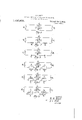
- FIG. 1 is a schematic diagram of an unequalized transformer system consisting of a transformer (J J J and the two exter nal impedances (R and R between which the transformer is connected; while Fig. 2
- lgs. 3, a, 5, 6 are diagrams of four different specific types of impedance-equalizers, constituting specific embodiments of my invention.
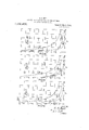
- Figs. 7, 8, 9, 10 and 11 present a series of curves illustrating the precision of the impedance-equalization accomplished by the several types-of equalizers above mentioned.
- Fig. 1 which represents an unequalized transformer system
- J, and J respectively denote the self-impedances of the primary and secondary windings of the transformer, and J denotes their mutual impedance; while It, and R respectively denote theprimary and secondary external impedances between which the transformer is connected.
- one of these impedances may be that of a transmission line while the other may be that of a repeater.
- Fig. 2 represents the system of Fig. 1 augmented by two impedances Z and Z in series with the primary and secondary circuits respectively.
- Z and Z will represent the impedances of the two equalizer-units (the number of the equalizer units being two in order to admit of accomplishing impedance equalization simultaneously in the two directions).
- formulas exformer impedances J a T T T then the complete and exact formpressing the properties of the unequalized system of Fig. 1 need not be separately developed, as they can be immediately dcduced from the corresponding formulas for the system of Fig. 2 merely by setting Z and Z, each equal to zero therein.
- the primary driving-point impedance 1 being the total impedance offered by the system to an E. M. F. inserted in the primary circuit when there is no other E. M. F. in the system;
- Equation (8) shows that for an idealtransformer former. From these considerations we now see on referring back to equation (8), which is the'formula for the primary drivingpoint impedance of any actual transformer system, that the last term therein represents the effect of magnetic leakage and that the next to the last term represents the effect resulting from the impedance of the transformer-winding bein finite rather than infinite, the ratio R,/ 2 becoming zero only llt t the 'ap- V proprlate impedance-ratio of t e trans- That this is exactly true for an ideal transmaximum power into a receiver (whose im-- former can be seen from equation (10), which shows that, when I /J is equal to R /It S -R is equal to R in other words, that the effective resistance S R to which the primary external resistance R is connected has then a value equal to R which is just the value to absorb maximum power from any electromotive force located in the primary external resistance having the fixed value R -it being well-known that any fixed source of electro
- each equallzer-unit consists of a condenser, as represented in Fig. 3; where 0 and c denote the capacities ofthe primary and secondary units respectively.
- Z :-i/p0 and z zi/pc and therefore, by (19) and (17)
- h the best value for the parameter h is approximately 2; but of course my invention is not restricted to the employment of any particular value of h.
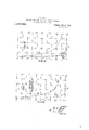
- each equalizer-unit consists of a condenser shunted by a resistance as representedin Fig. 4; where 0 and 1*, denote respectively the capacity and the resistance of the elements composing the primary unit, and c and r, the capacity and resistance of the elements composing the secondary unit.
- each equalizer-unit consists of a condenser shunted by an in-' ductance, as represented in Fig. 5, where a, and d, denote respectively the capacity and the inductance of the elements composing the primary unit, and c and the capacity and inductance of the elements composin the secondary unit.
- each equalizer-unit consists at three elements in parallel with each other; namely a condenser, a resistance, and an inductance, as represented by Fig. 6, where 0 d 1*, denote respectively the capacity, inductance and resistance of the elements comprisin the primary unit, and 0,, 0Z 9",, those of t e secondary unit.
- This type of equalizer includes the practical advantage, possessed also by the condenser-inductance type, of ofi'er but little obstruction to the flow of very low frequency currents, particularly direct currents. In addition, owing to its greater number of elements, it admits of a wider range of proportioning than the types dis closed above.
- equation 52 is generic in that it gives the relations when capacity, resistance and inductance are included in the equalizers, as shown in Fig. 6.
- the resistance element is omitted, it is equivalent to makin is equal to infinity. If the inductance e ement is omitted, it is equivalent to making g equal to infinity, and finally, if the capacity element is omitted, it is equivalent to making it equal to zero.
- the external impedance on the one side of the transformer should be substantially equal to the apparent impedance of the other external impedance as seen through the transformers and the associated impedance equalizers.
- a transmission system comprising a transformer interposed between two external impedances,'and e ualizing impedance elements associated wiai each winding of the transformer, said equalizingimpedance 65 elements being so proportioned with reference to the external impedances and the self-inductances of the windings of the transformer, that if either external impedance be disconnected, the impedance of the remainder of the system will be substantially equal, over a considerable range of frequencies, to that of the disconnected external impedance.
- a transmission system comprising a transformer interposed between two external impedances, and equalizing impedance elements associated with each winding of the transformer, said equalizing impedance elements being so proportioned with ref;
- equalizin impedance elements being so proportione with reference to the external impedances and the self inductances of the windings of the transformer that if either external impedance be disconnected, the impedance of the remainder of the system will be substantially equal, over a considerable range of frequencies, to that of the disconnected external impedance.
- a transmission system comprising a transformer interposed between two external impedances, and equalizing impedance elements including a capacity associated with each winding of the transformer, said equalizing impedance elements being so proportioned with reference to the external im pedances and the constants of the transformer that if either external impedance be disconnected, the impedance of the remainder of the system will be substantially equal, over a considerable range of frequencies, to that of the disconnected external impedance.
- a transmission system comprising a transformer interposed between two external impedances, and equalizing arrangements associated with each winding of the transformer, said equalizing arrangements in-'- cluding a capacity in parallel with an impedance element, said equalizing arrangementsbeing so proportioned with reference to the external impedances and the self-inductances of the windings of the transformer, that if either external impedance be disconnected, the impedance of the remainder of the system will be substantially equal, over a considerable range of frequencies, to that of the disconnected external impedance.
- a transmission system comprising a transformer interposed between two external impedances, and equalizing arrangements associated with each winding of the transformer, said equalizing arrangements including a capacity in parallel with an impedance element, said equalizing arrangements being so proportioned with reference to the external impedances and the constants of the transformer, that if either external impedance be disconnected, the impedance of the remainder of the system will be substantially equal, over a considerable range of frequencies, tothat of the disconnected external impedance.
- An arrangement to associate circuits of unequal impedances comprising a transformer, an impedance element in the primary circuit of the transformer and an impedance element in the secondary circuit of the transformer, these impedance elements being so proportioned respectively that the impedance of either associated circuit is subetantially equal over a considerable fre quency range to the impedance of the other associated circuit as seen when looking through the transformer towards the said other impedance.
- a transformer comprising primary and secondary windings, circults associated with each of said windings, and means associated with each of said windings whereby the impedance of each of said associated circuits is rendered substantially equal over a wide frequency range to the impedance of the other associated circuit as seen when viewed through the transformer and the associated means.
- a transmission system comprising a transformer interposed between two external impedances, an equalizing impedance associated with each winding of the transformer, said equalizing impedances including a resistance in parallel with the capacity, the values of these two being adjusted with respect to each other and to the constants of the transformer and the external impedances in accordance with the relation
- this twenty-fifth day of November, 1918 In testimony whereof I have signed my name to this specification this twenty-fifth day of November, 1918.
Landscapes
- Engineering & Computer Science (AREA)
- Computer Networks & Wireless Communication (AREA)
- Signal Processing (AREA)
- Cable Transmission Systems, Equalization Of Radio And Reduction Of Echo (AREA)
Description
msww
R. s. HOYT.
TWO WAY IMPEDANCE EQUALIZER FOR TRANSFORMERS. APPLICATION FILED NOV:29.1918.
Patented Oct. 3, 1922.
3 SHEETS-SHEET l.
IENTOR.
A TTORNEY R. S. HOYT.
TWO WAY IMPEDANCE EQUA'LIZER FOR TRANSFORMERS. APPLICATION FILED NOV. 29, 1918.
1,430,808. Patented 0st. 3, 1922.,
3 SHEETSSHEET 2.
NVENTOR.
ATTORNEY R. S. HOYT.
TWO WAY IMPEDANCE EQUALIZER FOR TRANSFORMERS.
APPLICATION HLED NOV. 29, 1918- 1 %8Q580g, Patented 0015. 3, 19220 3 SHEETS-SHEET 3.
L a/K IN V EN TOR. w
A TTORNE Y Patented Oct. 31, 1922.
lTED TAT'ES S. HOYT, OF BROOKLYN, NEW YORK, ASSIGN'OR T0 AMERIGAN TELEPHONE AND TELEGRAPH COMPANY, A. CUORATIGN OF NEW YORK.
TWO-WAY IMPEDANCE EQUALIZER FOB TRA'NSFQZRMEBS.
Application filed November as, 1918. Serial No. 264,656;
7 '0 all whom it may concern: 4
Be it known that I, RAY S. Hon, residing at Brooklyn, in the county of Kings and State of New York, have invented certain Improvements in Two-Way Impedance Equalizers for Transformers, of which the following is a specification.
This invention relates to a circuit arrangement, or network, to be associated with an electrical transformer system, (that is, a transformer together with the two external impedances between which the transformer is connected). The object of this invention is to provide a simple network having such an electrical impedance that when said network is duly associated with the transformer system the resultant impedance of the-combined system shall thereby be rendered closely equal to its ideal value, over a wide range of frequencies such, for instance, as the range of frequencies essential forthe telephonic transmission of speech. The-special name impedance-equalizer. is here given to this network because the ideal value of the impedance of the transformer system would in the most important practical cases be approximately independent of frequency, while its actual value would vary considerably or greatly with frequency; so that the result then accomplished by the network would be theequalization of the impedance of the system with reference to frequency.
My invention is capable of many and varied uses but is of particular utility when associated with transformers occurring in a transmission system containing two-way repeaters.
This invention is in the nature of an improvement on that already disclosed in my Patent Serial No. 1,333,111, March 9, 1920. Said patent relates to a one-way equalizer adapted for equalizing the impedance. for only one side of the transformer (either the primary side or the secondary side) and thus possesslng the desired property onlyfor transmission in one of the two directions. Such one-way equalization suffices in many applications, particularly in those involving only a single two-way repeater; but in many other applications, particularly those involving a plurality of two-way repeaters, twoway equalization, such as accomplished by my present invention, becomes important.
' My invention is best understood by reference to the accompanying drawings, in which Fig. 1 is a schematic diagram of an unequalized transformer system consisting of a transformer (J J J and the two exter nal impedances (R and R between which the transformer is connected; while Fig. 2
IS the corresponding diagram of an equalized transformer system, Z and Z respec tively denoting the impedances of the primary and secondary units which together compose the equalizer. These two diagrams- -particularly that of Fig. 2are here provided in order to assist in understanding the development of certain general underlyin% formulas employed. below.
lgs. 3, a, 5, 6 are diagrams of four different specific types of impedance-equalizers, constituting specific embodiments of my invention.
Figs. 7, 8, 9, 10 and 11 present a series of curves illustrating the precision of the impedance-equalization accomplished by the several types-of equalizers above mentioned.
The general theory underlying the impedance-equalizers of this invention will now be developed, after which certain specific types will be disclosed and the appropriate design-formulas will be derived.
In Fig. 1, which represents an unequalized transformer system, J, and J respectively denote the self-impedances of the primary and secondary windings of the transformer, and J denotes their mutual impedance; while It, and R respectively denote theprimary and secondary external impedances between which the transformer is connected. In practice one of these impedances may be that of a transmission line while the other may be that of a repeater.
or the purpose of developing the underlying general theory consider Fig. 2, which represents the system of Fig. 1 augmented by two impedances Z and Z in series with the primary and secondary circuits respectively. In the application of the general theory, Z and Z will represent the impedances of the two equalizer-units (the number of the equalizer units being two in order to admit of accomplishing impedance equalization simultaneously in the two directions). Evidently, formulas exformer impedances J a T T T then the complete and exact formpressing the properties of the unequalized system of Fig. 1 need not be separately developed, as they can be immediately dcduced from the corresponding formulas for the system of Fig. 2 merely by setting Z and Z, each equal to zero therein.
Because of the nature of the function to be performed by the impedance-equalizer we are concerned with the primary and with the secondary driving-point impedances of the system of 2; the primary driving-point impedance 1 being the total impedance offered by the system to an E. M. F. inserted in the primary circuit when there is no other E. M. F. in the system;
while the secondary driving-point impedwhich, solved for the ratios I /E an I /E give which, though in a sense more complicated than (6), possesses the advantage of exhibiting the hysical relations more clearly. Thus, (8) s ows that, for a transformer having no magnetic leakage,
I 1 z/ z '11 S1 FJ, 1+R, J J (9) the well-known condition for no magnetic leakage being L L =L (see Bedell, The principles of the transformer, 1896, page 197) which can be written very closely as J J =J That this approximation is warranted ma be demonstrated as follows:
f the resistance com onents of the trans- J be denoted by ulae for J J J will evidently be J2 ZT2+74ZL2 J12=T12+747L12 Now, for an eflicient or even fairly efficient transformer the resistance components T T T are small compared with the reactance components z'pL z'pL 'ipL corresponding to the Well-known fact that for such a transformer the magnetizing current is nearly wattless, and hence the angles of the transformer iinpedances are nearly 90. O'onsequentl we may write, J :z'pL J,:ipL and :z'gvL Since by the preceding equations, the impedance s, being, by definition, the value of E /l when E =O, we find from (2), by putting E =O therein, that Similarly, by putting E,:O in (3), we find that In order to exhibit the need for an impedance-equalizer we shall apply the preceding general formulas to the unequalized system of Fig. l by setting Z and Z each equal toazero and denoting the corresponding values of S and S by S and S respectively, so that S2 :'J2+R2' J122/(J1+R1) These being similar to each other in form, it will suffice to discuss only one of them, say the formula for S This can berewritten in the form is approximately proportional to the inductance, the expression J J =J may be substituted for the formula given by Bedell. If this value be substituted in the last term of equation 8, it will be seen that this term vanishes so that equation 8 becomes equat1on 9, as previously indicated.
Further, (8) shows that for an idealtransformer former. From these considerations we now see on referring back to equation (8), which is the'formula for the primary drivingpoint impedance of any actual transformer system, that the last term therein represents the effect of magnetic leakage and that the next to the last term represents the effect resulting from the impedance of the transformer-winding bein finite rather than infinite, the ratio R,/ 2 becoming zero only llt t the 'ap- V proprlate impedance-ratio of t e trans- That this is exactly true for an ideal transmaximum power into a receiver (whose im-- former can be seen from equation (10), which shows that, when I /J is equal to R /It S -R is equal to R in other words, that the effective resistance S R to which the primary external resistance R is connected has then a value equal to R which is just the value to absorb maximum power from any electromotive force located in the primary external resistance having the fixed value R -it being well-known that any fixed source of electromotive force (whose impedance is pure resistance) will deliver pedance is pure resistance) when the .resistance of the receiver is made equal to the resistance of the source. To prove this latter theorem, let E and R denote the (fixed) electromotive force and resistance of the source, a" the resistance of the receiver, I the lzli ihrrent, and P the power absorbed by r.
' rE P a: 7'1 m which, for fixed E and It but variable 7', can readily be shown (by differentiation, for instance) to be a maximum when a" is made equal to a In applying this general theorem to the particular system consisting of R and R connected by a transformer, it is to be noted that the transformer has been regarded as ideal and hence as transmitting power without any dissipation. For an efficient or even fairly efficient actual transformer, this would still be closely true and hence the optimum value of Il /l3 v closely equal to R /R so closely, in fact, that this is ordinarily adopted as the optimum value and will thus be adopted in the presentation of the equalizer theory later herein If the transformer connecting R and R were ideal and had the optimum impedance range of frequencies; for a transformer ratio J /J =]R /R then by (10) the value of 5, would be merely 2B,, and similarly the value of S Would be merely 2R and therefore the difierence S 2R and the differ ence S -2It would each be zero. For an actual transformer, unequalized, these dlfierences would be quite large over a considerable equipped with impedance-equalizers, the smallness of these differences would be a prec'ision-measure of the degree of equalization accomplished. In practice it is convenient to take R and R as standards of reference in determinin the relative magnitudes of Sa -2R and -2R that is, the natural criteria as to the degree of equalization accomplished are the quantities D and D defined by the equations which may conveniently be'termed the fractional deviations. In ordinary a plications their absolute values EDA} and l i, regarded as functions of the frequency, are the functions of chief significance in indicating the degree of equalization.
In ordinary practice the impedance-distortion due to the magnetic leakage of a transformer is quite small compared with the distortion due to its self and mutual impedances being finite rather than infinite. In what follows, magnetic leakage will therefore be neglected, as the discussion is thereby greatly simplified without introducing any substantial error. Introducing into (4) the condition J :5 d 2 for no magnetic leakage, and substituting into (11). the resulting value of S we find that D1 1 +z n +J /R a, (13) Similarly Henceforth it will be assumed that the transformer has the proper inductance-ratio for securing maximum power transmitted,
namely l/ 2 l/ 2 that is L1/R1IL2/R2 whence J /R zJ /R ziQ Y I (17) where When the impedance-equalizer units are omitted-which is evidently equivalent to putting Z :Z :O' in formulas (4:) and (5), and hence W:O in (20) and (21)-the corresponding value of D, which will be denoted by D is expressed by the simple formula D =-1/(1+iQ) (22) whence ol= /1/ +Q 3)- On each of the drawings. (cited below) which show the characteristics of the several s ecific types of eqpalizers disclosed, is in-- c uded a graph of I I to serve as a standard of comparison toindicate the degree of impedance-equalization attained, D being the value of D for the unequalized system.
Condenser type of equalizer.
The type of equalizer disclosed under this heading is one in which each equallzer-unit consists of a condenser, as represented in Fig. 3; where 0 and c denote the capacities ofthe primary and secondary units respectively. Hence Z :-i/p0 and z zi/pc and therefore, by (19) and (17) As the result of a series of computations and plottings of lDl as function of Q with h as parameter, I discovered that, for the range of ordinary practical applications,.the best value for the parameter h is approximately 2; but of course my invention is not restricted to the employment of any particular value of h. Fig. 7 gives a gra h of [DB computed from (27) with h=2; ailso a graph of which is the value of D when the equalizers are omitted. Comparison of these two graphs shows the very great improvement accomplished by the impedance-equalizer; the equalization being nearly complete except at such small values of Q as Would usually be unimportant in practice.
With the value of theparameter h once chosen, the equalizer-elements are completely detefmined, the design-formulas being, by
lD icomputed from (23) Condenser-resistance type of equalizer.
The type or" equalizer disclosed under this heading is one in which each equalizer-unit consists of a condenser shunted by a resistance as representedin Fig. 4; where 0 and 1*, denote respectively the capacity and the resistance of the elements composing the primary unit, and c and r, the capacity and resistance of the elements composing the secondary unit.
For this type of equalizer Hence, by (19) and (17 W=la/(1+ikkQ) (so where k: 1 1 1 z z z and In addition to the parameters It and la defined by (31) and (32), it is convenient to introduce a further parameter at defined by the equation tz-hk, so that Then, substituting into 20 the value of W given by (34), we find that Y from which the value of ID! can be calcu lated for any chosen values of the parameters is and t. As the result of a series of computations and plottings of lDl as function of Q with k and t as parameters, I discovered that, for the ordinary range of practical applications the best pairs of values are approximately those 1 ing within the range covered by the following table:
' is. t.
The particular pair of values of k and t so that Oondeneer-indtwtaace type of equalizer.
The type of equalizer disclosed under this heading is one in which each equalizer-unit consists of a condenser shunted by an in-' ductance, as represented in Fig. 5, where a, and d, denote respectively the capacity and the inductance of the elements composing the primary unit, and c and the capacity and inductance of the elements composin the secondary unit.
Pro ably the chief practical advantage of this type of equalizer over the simple condenser type wouldbe in such applications as might require a by-pass for currents of very low frequencyi11 particular, direct currents; as the inductance-elements 03 and d constitute such by-passes and at the same time can be so proportioned as not to afi'ect the equalization-characteristics materially.
For this type of equalizer Z2 p z/ 1 2 2) (38) Hence, by (19) and (17 9Q/( gQ) where l l 1 2 z L2 and It is convenient to introduce a further parameter b defined by the equation it/ IF? 4 2 e whence combinations (0,, al and (0 01,) is anti-V resonant.
Because of its length, the formula for D in terms of b, g, Q has been omitted here;
0 =11 lb gR 2 2=LWRZQ an; e 00ndemar-resista'rwe-inductancetype of equalizer.
The type of equalizer disclosed under this heading is one in which each equalizer-unit consists at three elements in parallel with each other; namely a condenser, a resistance, and an inductance, as represented by Fig. 6, where 0 d 1*, denote respectively the capacity, inductance and resistance of the elements comprisin the primary unit, and 0,, 0Z 9",, those of t e secondary unit.
This type of equalizer includes the practical advantage, possessed also by the condenser-inductance type, of ofi'er but little obstruction to the flow of very low frequency currents, particularly direct currents. In addition, owing to its greater number of elements, it admits of a wider range of proportioning than the types dis closed above.
For this type of equalizer and an analagous formula for l/Z Hence, by (19) and (17),
where k:r /R :r /R (48) It is convenient to introduce a further parameter b defined by the equatlon Thus 6 is equal to the particular value of It will be noted that equation 52 is generic in that it gives the relations when capacity, resistance and inductance are included in the equalizers, as shown in Fig. 6. In this ll equation the term anc'e element of the equalizer, the teI I n ihQ, relates to the capacity element, and t ,5 erm relates to the resistrelates to the inductance element.
Ifthe resistance element is omitted, it is equivalent to makin is equal to infinity. If the inductance e ement is omitted, it is equivalent to making g equal to infinity, and finally, if the capacity element is omitted, it is equivalent to making it equal to zero. In any case, when equalization has been obtained, the external impedance on the one side of the transformer should be substantially equal to the apparent impedance of the other external impedance as seen through the transformers and the associated impedance equalizers.
By associating equalizing impedances of the character above described with a transformer system comprising a transformer interposed between two external impedances, the impedance of the remainder of the system, as viewed from either external impedance, may be made substantially equal, over a considerable range of frequencies, to said external impedance. It will also be obvious that the general principles herein disclosed may be embodied in many other organizations widely different from those illustrated without departing from the spirit of the invention as definedin the following claims.
What is claimed is:
1. A transmission system comprising a transformer interposed between two external impedances,'and e ualizing impedance elements associated wiai each winding of the transformer, said equalizingimpedance 65 elements being so proportioned with reference to the external impedances and the self-inductances of the windings of the transformer, that if either external impedance be disconnected, the impedance of the remainder of the system will be substantially equal, over a considerable range of frequencies, to that of the disconnected external impedance.
2. A transmission system comprising a transformer interposed between two external impedances, and equalizing impedance elements associated with each winding of the transformer, said equalizing impedance elements being so proportioned with ref;
equalizin impedance elements being so proportione with reference to the external impedances and the self inductances of the windings of the transformer that if either external impedance be disconnected, the impedance of the remainder of the system will be substantially equal, over a considerable range of frequencies, to that of the disconnected external impedance.
4. A transmission system comprising a transformer interposed between two external impedances, and equalizing impedance elements including a capacity associated with each winding of the transformer, said equalizing impedance elements being so proportioned with reference to the external im pedances and the constants of the transformer that if either external impedance be disconnected, the impedance of the remainder of the system will be substantially equal, over a considerable range of frequencies, to that of the disconnected external impedance.
5. A transmission system comprising a transformer interposed between two external impedances, and equalizing arrangements associated with each winding of the transformer, said equalizing arrangements in-'- cluding a capacity in parallel with an impedance element, said equalizing arrangementsbeing so proportioned with reference to the external impedances and the self-inductances of the windings of the transformer, that if either external impedance be disconnected, the impedance of the remainder of the system will be substantially equal, over a considerable range of frequencies, to that of the disconnected external impedance.
6. A transmission system comprising a transformer interposed between two external impedances, and equalizing arrangements associated with each winding of the transformer, said equalizing arrangements including a capacity in parallel with an impedance element, said equalizing arrangements being so proportioned with reference to the external impedances and the constants of the transformer, that if either external impedance be disconnected, the impedance of the remainder of the system will be substantially equal, over a considerable range of frequencies, tothat of the disconnected external impedance.
7. An arrangement to associate circuits of unequal impedances comprising a transformer, an impedance element in the primary circuit of the transformer and an impedance element in the secondary circuit of the transformer, these impedance elements being so proportioned respectively that the impedance of either associated circuit is subetantially equal over a considerable fre quency range to the impedance of the other associated circuit as seen when looking through the transformer towards the said other impedance.
8. In combination, a transformer comprising primary and secondary windings, circults associated with each of said windings, and means associated with each of said windings whereby the impedance of each of said associated circuits is rendered substantially equal over a wide frequency range to the impedance of the other associated circuit as seen when viewed through the transformer and the associated means.
9. A transmission system comprising a transformer interposed between two external impedances, an equalizing impedance associated with each winding of the transformer, said equalizing impedances including a resistance in parallel with the capacity, the values of these two being adjusted with respect to each other and to the constants of the transformer and the external impedances in accordance with the relation In testimony whereof I have signed my name to this specification this twenty-fifth day of November, 1918.
RAY S. HOYT.
Priority Applications (1)
| Application Number | Priority Date | Filing Date | Title |
|---|---|---|---|
| US264656A US1430808A (en) | 1918-11-29 | 1918-11-29 | Two-way impedance equalizer for transformers |
Applications Claiming Priority (1)
| Application Number | Priority Date | Filing Date | Title |
|---|---|---|---|
| US264656A US1430808A (en) | 1918-11-29 | 1918-11-29 | Two-way impedance equalizer for transformers |
Publications (1)
| Publication Number | Publication Date |
|---|---|
| US1430808A true US1430808A (en) | 1922-10-03 |
Family
ID=23007040
Family Applications (1)
| Application Number | Title | Priority Date | Filing Date |
|---|---|---|---|
| US264656A Expired - Lifetime US1430808A (en) | 1918-11-29 | 1918-11-29 | Two-way impedance equalizer for transformers |
Country Status (1)
| Country | Link |
|---|---|
| US (1) | US1430808A (en) |
Cited By (2)
| Publication number | Priority date | Publication date | Assignee | Title |
|---|---|---|---|---|
| US2669697A (en) * | 1948-07-15 | 1954-02-16 | Transformer Engineers | Transformer coupling network |
| US2921275A (en) * | 1953-11-02 | 1960-01-12 | Pye Ltd | Four-terminal networks |
-
1918
- 1918-11-29 US US264656A patent/US1430808A/en not_active Expired - Lifetime
Cited By (2)
| Publication number | Priority date | Publication date | Assignee | Title |
|---|---|---|---|---|
| US2669697A (en) * | 1948-07-15 | 1954-02-16 | Transformer Engineers | Transformer coupling network |
| US2921275A (en) * | 1953-11-02 | 1960-01-12 | Pye Ltd | Four-terminal networks |
Similar Documents
| Publication | Publication Date | Title |
|---|---|---|
| US2742616A (en) | Negative impedance repeaters | |
| US3168715A (en) | Trifilar wound hybrid transformer | |
| US2333148A (en) | Inductance apparatus | |
| US1430808A (en) | Two-way impedance equalizer for transformers | |
| US1227113A (en) | Electric wave-filter. | |
| US2029014A (en) | Wave transmission network | |
| US1227114A (en) | Electrical receiving, translating, or repeating circuit. | |
| US2204721A (en) | Impedance network for coupling electric cable circuits | |
| US2685066A (en) | Impedance inversion networks | |
| US3105125A (en) | Power separation filter | |
| US1615252A (en) | Electrical wave filter | |
| US1611932A (en) | Frequency selective-current transmission | |
| US1959494A (en) | System for voltage transformation of currents of wide frequency range | |
| US1601023A (en) | Electrical signaling system | |
| US1809839A (en) | Transformer and transformer system | |
| US1687253A (en) | Negative impedance device | |
| US2085952A (en) | Artificial network | |
| US2116172A (en) | Composite set | |
| US1665683A (en) | Telephone system | |
| US1776310A (en) | Two-way negative-impedance repeater | |
| GB397551A (en) | Improvements in electrical impedance networks and amplifiers | |
| US1548062A (en) | Coupling arrangement for multiplex transmission | |
| US2607860A (en) | Frequency selective repeater device | |
| US1243066A (en) | Network for neutralizing the characteristic reactance of a loaded line. | |
| US1605972A (en) | Arrangement for increasing the power of repeater circuits |