US1426975A - Connection of motor-vehicle wheels to the vertices of a rhombus - Google Patents
Connection of motor-vehicle wheels to the vertices of a rhombus Download PDFInfo
- Publication number
- US1426975A US1426975A US461092A US46109221A US1426975A US 1426975 A US1426975 A US 1426975A US 461092 A US461092 A US 461092A US 46109221 A US46109221 A US 46109221A US 1426975 A US1426975 A US 1426975A
- Authority
- US
- United States
- Prior art keywords
- wheels
- rhombus
- vertices
- connection
- springs
- Prior art date
- Legal status (The legal status is an assumption and is not a legal conclusion. Google has not performed a legal analysis and makes no representation as to the accuracy of the status listed.)
- Expired - Lifetime
Links
Images


Classifications
-
- B—PERFORMING OPERATIONS; TRANSPORTING
- B62—LAND VEHICLES FOR TRAVELLING OTHERWISE THAN ON RAILS
- B62D—MOTOR VEHICLES; TRAILERS
- B62D61/00—Motor vehicles or trailers, characterised by the arrangement or number of wheels, not otherwise provided for, e.g. four wheels in diamond pattern
- B62D61/02—Motor vehicles or trailers, characterised by the arrangement or number of wheels, not otherwise provided for, e.g. four wheels in diamond pattern with two road wheels in tandem on the longitudinal centre line of the vehicle
- B62D61/04—Motor vehicles or trailers, characterised by the arrangement or number of wheels, not otherwise provided for, e.g. four wheels in diamond pattern with two road wheels in tandem on the longitudinal centre line of the vehicle with two other wheels which are coaxial
Definitions
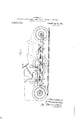
- T he present invention relates to a connecting arrangement for motor vehicle wheels situated at the vertices of arhombus, owing to which the vehicle platform rests on an resilient frame built up on each side by a pair of laminated sprin s pivotally connected with each other and with the axle of the driving wheels, the two springs of each pair beingarranged in alignment and'supporting the platform at points corresponding to the intersection of the springs with the centers of the ideal sides of the rhombus at whose vertices the wheels are fitted.
- a further characteristic feature of the invention consists in the fact that each guiding wheel is mounted on a vertical spindle or pivot, whose axis coincides with the center plane of the wheel.
- the said spindle being carried by axles whose one end is hinged to one end of an arch-shaped crossbar forming the header of the vehicle elastic frame and whose other end is removably secured to the other end of said crossbar.
- connection among the wheels is given by an elastic frame comprising four laminated springs 12, the two springs arranged on the same side of the rhombus being interlinked in alignment and having the fore and respectively the rear free ends connected by headers 13 having the form of an arch; at one end of the headers 13 are hinged at 14 the axles 10-11. whilst at the other header end 15 the said axles are secured to the header by a screw-nut.
- the axle can be pivoted about its pivot 14. and the wheel or the rim of the rubber tyre can be taken out.
- the elastic frame carries the vehicle platform through the intermediary of pins 17 arranged at the points where the ideal sides of the rhombus ABC-D cross the springs building up the vehicle frame.
- the springs 12 act sometimes as springs, sometimes as balancers g i g 1 ,42e,975
- the platform directly carries the driving set 1-9'oompr1sing the engine, the change speed with controlling gear, the differential and the brakes acting upon the latter.
- the position of the driving set 19 is such that the axis of. the differential practically coincides with the axis XY of the driving wheels, so that the motion is transmitted to the wheels directly across the "axles 20 and the Cal dan couplings 21, the longitudinal shaft existing in all motor vehicles being dispens'ed with.
- the platform directly supports also the remaining parts of the vehicle viz radiator, tank, steering gear, car body and accessories.
- the steering gear simultaneously acts up on bothguidin'g wheels 67 in the following manner: 7 i
- the worm gear enclosed'in the box 23 actuates the cross shaft 2 1- on whose ends are keyed thecranks of equal length 25,
- the two guiding wheels By operating the steering handwheel, the two guiding wheelsare swung about their vertical pivot by equal angles but in oppo site direction, so that their main axes meet at a point 0 which is always situated on the cross axis XY; the vehicle turns about this point Q.
- the point 0 coincides with the centre A or B ofone of the driving wheels, this wheel forms the rotation center of the vehicle and ceases to turn, whilst the other wheel alone undertakes the whole of the driving function due to the interposed differential.
- Connecting arrangement for .motor vehicle wheels situatedat the vertices of a rhombus comprising an elastic frame built up on each side by a pair of laminated aligned springs pivotally connected with with each other and with the axle of the driving wheels carrying the vehicle platform at points corresponding to the intersection of the springs with the centers of the ideal sides of the rhombus at whose vertices the wheels are arranged, and connected to the free ends of arched headers to one end of which is hinged one end of the axle of the guiding wheels, whilst to the other end of the header is secured by means of a screwnut the other end ofthe same axle, substantially as described and illustrated and for the purposes set out above.
- each guiding wheel is mounted on a vertical spindle or pivot carriedbythe 'wheels axle and whose*axislies in the center plane of the wheel, substantially as described and illustrated.
Description
APPLICATION FILED APR-13,1921.
Patented Aug. 22, 1922.
3 SHEETS-SHEET 1.
mwaida;
O. FUSCALDO. CONNECTION OF MOTOR VEHICLE WHEELS TO THE VERTICES OF A RHOMBUS.
' APPLICATION FILED APR. I3. 192]- 1,426,975.
Patented Aug. 22, 1922.
3 SHEETSSHEET 2.
O. FUSCALDO.
CONNECTION OF'MOTOR VEHICLE WHEELS TO THE VERTICES OF A RHOMBUS.
APPLICATION FILED APR-13, I921.
Patented Aug. 22, 1922.
3 SHEETSSHEET 3.
OTTAVIO FUSCAIJDO,
0F BRESCIA, ITALY.
CONNECTION OF MOTOIR-VEHICLE "WHEELS TO THE VERTICESOF A RHOMBUS.
nsane/s.
Application filed. April 13,
T 0 all 1!] Ito M it may concern Be it known that I, GT'rAVio FUsoALDo, subject of the King of Italy, residing at 4: Via Mario Alberto, Brescia, Kingdom of Italy, have invented certain new and useful 'trrangeincnts for Connection of Motorl ehicle Va heels to the Vertices of a Rhombus, of which the following is a specification.
T he present invention relates to a connecting arrangement for motor vehicle wheels situated at the vertices of arhombus, owing to which the vehicle platform rests on an resilient frame built up on each side by a pair of laminated sprin s pivotally connected with each other and with the axle of the driving wheels, the two springs of each pair beingarranged in alignment and'supporting the platform at points corresponding to the intersection of the springs with the centers of the ideal sides of the rhombus at whose vertices the wheels are fitted.
A further characteristic feature of the invention consists in the fact that each guiding wheel is mounted on a vertical spindle or pivot, whose axis coincides with the center plane of the wheel. the said spindle being carried by axles whose one end is hinged to one end of an arch-shaped crossbar forming the header of the vehicle elastic frame and whose other end is removably secured to the other end of said crossbar.
From the said novel arrangements a novel practical suspension system results which in conjunction with the constructional details set out hereinafter permits of the practical adoption of the rhombus arrangement of the wheels with the following advantages over the other motor vehicle arrangements heretoferc used and known:
1. Rational and exceptionally elastic suspension even when travelling on very uneven ground.
Practically exact turning of the vehido, to such a degree that the vehicle can turn upon one of its driving wheels as turning center.
3. Lightness of construction.
4. High efficiency due to several parts being simplified or dispensed with and to the form of the body matching the arrangement of the vehicle parts and being more adapted to overcome the air resistance.
lhe annexed drawing shows, by way of example, one execution form of the invention.
1 is a diagrammatic view of the Specification oi Letters Patent. Patented Aug. 22, 1922.
1921. Serial No. 461,092.
ordinarily arranged at the verticesof the obtuse angles of the rhombus and keyed to spindles 8 adapted to swivel inside-oft'he ball bearing hubs 4:, solid with the center (1X16 1 6 and 7 are the guiding wheels arranged at the acute angles of the rhombus for which the resistance arm or overhang arm is reduced to zero by adopting the lodging ar-v rangement forming the subject matter of my copending application-Serial No. 461,091 according to which the axis of the vertical spindle about which the wheel is adapted to swivel coincides with the center plane of the wheel. Each guiding wheel accordinglyv runs on a ball bearing 8 containing the vertical spindle about whose axis-the axles'lO and 11 are pivoting.
In this way the centres of the four wheels 1, 2, 6 and? are arranged at the vertices of a rhombus ii. B-CD, in which theaxis X-Y of the driving wheels constitutes the shorter diagonal.
The connection among the wheels is given by an elastic frame comprising four laminated springs 12, the two springs arranged on the same side of the rhombus being interlinked in alignment and having the fore and respectively the rear free ends connected by headers 13 having the form of an arch; at one end of the headers 13 are hinged at 14 the axles 10-11. whilst at the other header end 15 the said axles are secured to the header by a screw-nut.
Owing to this arrangement, once the header is lifted by means of a jack applied at 16 and the screw-nut 15 has been slackened, the axle can be pivoted about its pivot 14. and the wheel or the rim of the rubber tyre can be taken out.
The elastic frame carries the vehicle platform through the intermediary of pins 17 arranged at the points where the ideal sides of the rhombus ABC-D cross the springs building up the vehicle frame.
With this arrangement the springs 12 act sometimes as springs, sometimes as balancers g i g 1 ,42e,975
and sometimes in both capacities according to the conditions of .the road pavement. Since namely the irregularities of the road produce a jolting effect on the four wheels, in the case that the four wheels simultaneously meet four equal obstacles or fourequal holes, the jolting will be transmitted to the platform in a dampeddegree by the four springs. In the case the two leading wheels mount upon two obstacles whilst the driving' Wheels sink into holes as deep as the obstacles are high (or conversely) the sinking of the wheels (of positive sign for one wheel pair and of negative sign for the other pair) will have a maximum value, but no shakingeffect will be transmitted to the latforni because the center points E F -H where the connection between the platform and the'springs is effected remain at rest. f 1 V a In. the former case a bending of the springs will take place, in the latter case there will be no bending and the springs will merely behave as ba'lancers. Since all thenumberless cases that may occur are comprised between the two extremes we have just examined, it is plain that the connecting points EFG-H Tare those with 1 which "the least amount of jolting takes place when running on uneven ground.
The platform directly carries the driving set 1-9'oompr1sing the engine, the change speed with controlling gear, the differential and the brakes acting upon the latter. The
position of the driving set 19 is such that the axis of. the differential practically coincides with the axis XY of the driving wheels, so that the motion is transmitted to the wheels directly across the "axles 20 and the Cal dan couplings 21, the longitudinal shaft existing in all motor vehicles being dispens'ed with.
The platform directly supports also the remaining parts of the vehicle viz radiator, tank, steering gear, car body and accessories.
The steering gear simultaneously acts up on bothguidin'g wheels 67 in the following manner: 7 i
The worm gear enclosed'in the box 23 actuates the cross shaft 2 1- on whose ends are keyed thecranks of equal length 25,
Through the tie rods 26 and 27 and hinged .equal in length and secured to the inner boxes 9 enclosing the ball bearings of the wheels.
By operating the steering handwheel, the two guiding wheelsare swung about their vertical pivot by equal angles but in oppo site direction, so that their main axes meet at a point 0 which is always situated on the cross axis XY; the vehicle turns about this point Q. When the point 0 coincides with the centre A or B ofone of the driving wheels, this wheel forms the rotation center of the vehicle and ceases to turn, whilst the other wheel alone undertakes the whole of the driving function due to the interposed differential. I i .,Having now particularly described and ascentained the nature of my said invention and in what manner the same is to be performed, I declare that what I claim is 2- 1. Connecting arrangement for .motor vehicle wheels situatedat the vertices of a rhombus, comprising an elastic frame built up on each side by a pair of laminated aligned springs pivotally connected with with each other and with the axle of the driving wheels carrying the vehicle platform at points corresponding to the intersection of the springs with the centers of the ideal sides of the rhombus at whose vertices the wheels are arranged, and connected to the free ends of arched headers to one end of which is hinged one end of the axle of the guiding wheels, whilst to the other end of the header is secured by means of a screwnut the other end ofthe same axle, substantially as described and illustrated and for the purposes set out above.
2. Connecting arrangement for motor vehicle wheels as per claim 1 in which each guiding wheel is mounted on a vertical spindle or pivot carriedbythe 'wheels axle and whose*axislies in the center plane of the wheel, substantially as described and illustrated. 3 i i Signed" at Milan (Italy), this day of lelarch 1921. I
O TTAVIO- FUSCALDO,
Priority Applications (4)
| Application Number | Priority Date | Filing Date | Title |
|---|---|---|---|
| US461092A US1426975A (en) | 1920-04-26 | 1921-04-13 | Connection of motor-vehicle wheels to the vertices of a rhombus |
| FR534608D FR534608A (en) | 1920-04-26 | 1921-04-25 | Device for connecting the wheels of motor vehicles to the vertices of a rhombus |
| GB1196721A GB162291A (en) | 1920-04-26 | 1921-04-26 | |
| DER52856D DE384072C (en) | 1920-04-26 | 1921-04-26 | Motor vehicle |
Applications Claiming Priority (2)
| Application Number | Priority Date | Filing Date | Title |
|---|---|---|---|
| IT534608X | 1920-04-26 | ||
| US461092A US1426975A (en) | 1920-04-26 | 1921-04-13 | Connection of motor-vehicle wheels to the vertices of a rhombus |
Publications (1)
| Publication Number | Publication Date |
|---|---|
| US1426975A true US1426975A (en) | 1922-08-22 |
Family
ID=23831194
Family Applications (1)
| Application Number | Title | Priority Date | Filing Date |
|---|---|---|---|
| US461092A Expired - Lifetime US1426975A (en) | 1920-04-26 | 1921-04-13 | Connection of motor-vehicle wheels to the vertices of a rhombus |
Country Status (4)
| Country | Link |
|---|---|
| US (1) | US1426975A (en) |
| DE (1) | DE384072C (en) |
| FR (1) | FR534608A (en) |
| GB (1) | GB162291A (en) |
Cited By (7)
| Publication number | Priority date | Publication date | Assignee | Title |
|---|---|---|---|---|
| US2485770A (en) * | 1947-05-14 | 1949-10-25 | Charles I Place | Wheel and frame assembly |
| US3520378A (en) * | 1966-06-23 | 1970-07-14 | Reginald Arthur Slay | Motor-driven wheeled vehicles |
| US4775021A (en) * | 1986-07-30 | 1988-10-04 | Silvio Marino | Automotive vehicle having four wheels in a rhomboidal configuration |
| US6050367A (en) * | 1998-06-22 | 2000-04-18 | Tvetene; Theodore | Bi-directional vehicle |
| US7243746B1 (en) | 2003-06-09 | 2007-07-17 | Abraham Vasant | Recreational electric vehicle |
| EP1982905A1 (en) | 2007-04-20 | 2008-10-22 | C.R.F. Societa Consortile per Azioni | Electrically powered vehicle, having wheels arranged in a rhombus-like configuration |
| US20170156951A1 (en) * | 2014-06-24 | 2017-06-08 | Bendt Ipr Aps | Chassis for vehicle |
Families Citing this family (4)
| Publication number | Priority date | Publication date | Assignee | Title |
|---|---|---|---|---|
| DE1243990B (en) * | 1962-11-28 | 1967-07-06 | Kaessbohrer Fahrzeug Karl | Three-axle motor vehicle for transporting people or loads |
| MC1272A1 (en) * | 1979-04-24 | 1980-05-23 | P Bunoust | NEW "CONTINUOUS" AND COMBINED-INDIVIDUAL-OR TWO-ROAD TRANSPORT-EITHER TRAFFIC-BY RAIL-AIR OR MARINE-FOR URBAN-METROPOLITAN OR INTERNATIONAL "ULTRA-FAST" TRAVEL |
| FR2692220B1 (en) * | 1992-06-16 | 1998-06-12 | Philippe Charbonneaux | ROAD VEHICLE WITH IMPROVED WHEELS. |
| DE102017002347A1 (en) | 2016-09-10 | 2018-03-15 | Benoit Dehais | Vehicle with central drive |
-
1921
- 1921-04-13 US US461092A patent/US1426975A/en not_active Expired - Lifetime
- 1921-04-25 FR FR534608D patent/FR534608A/en not_active Expired
- 1921-04-26 GB GB1196721A patent/GB162291A/en not_active Expired
- 1921-04-26 DE DER52856D patent/DE384072C/en not_active Expired
Cited By (8)
| Publication number | Priority date | Publication date | Assignee | Title |
|---|---|---|---|---|
| US2485770A (en) * | 1947-05-14 | 1949-10-25 | Charles I Place | Wheel and frame assembly |
| US3520378A (en) * | 1966-06-23 | 1970-07-14 | Reginald Arthur Slay | Motor-driven wheeled vehicles |
| US4775021A (en) * | 1986-07-30 | 1988-10-04 | Silvio Marino | Automotive vehicle having four wheels in a rhomboidal configuration |
| US6050367A (en) * | 1998-06-22 | 2000-04-18 | Tvetene; Theodore | Bi-directional vehicle |
| US7243746B1 (en) | 2003-06-09 | 2007-07-17 | Abraham Vasant | Recreational electric vehicle |
| EP1982905A1 (en) | 2007-04-20 | 2008-10-22 | C.R.F. Societa Consortile per Azioni | Electrically powered vehicle, having wheels arranged in a rhombus-like configuration |
| US20170156951A1 (en) * | 2014-06-24 | 2017-06-08 | Bendt Ipr Aps | Chassis for vehicle |
| US10470952B2 (en) * | 2014-06-24 | 2019-11-12 | Bendt Ipr Aps | Chassis for vehicle |
Also Published As
| Publication number | Publication date |
|---|---|
| FR534608A (en) | 1922-03-29 |
| DE384072C (en) | 1923-10-25 |
| GB162291A (en) | 1922-07-13 |
Similar Documents
| Publication | Publication Date | Title |
|---|---|---|
| US2463310A (en) | Independently suspended motor vehicle characterized by a low center of gravity | |
| US1426975A (en) | Connection of motor-vehicle wheels to the vertices of a rhombus | |
| Campbell | Automobile suspensions | |
| US20180273101A1 (en) | Motorised Karts | |
| US2092612A (en) | Automobile suspension system | |
| US3161250A (en) | Multiple-wheel articulated drive axle and vehicle | |
| US2029735A (en) | Automotive body and frame | |
| US1149153A (en) | Running-gear for vehicles. | |
| US3512802A (en) | Tractor rig | |
| US4522418A (en) | Steerable wheel suspension arrangement | |
| US2901264A (en) | Dual front axle suspension means and steering mechanism therefor | |
| US1973144A (en) | Multiwheel twin-motor road vehicle | |
| US1095127A (en) | Vehicle. | |
| US3279556A (en) | Vehicle suspension system | |
| US2071480A (en) | Vehicle suspension mechanism | |
| US1885427A (en) | Driving mechanism for motor vehicles | |
| US2552320A (en) | Vehicle frame and spring structure | |
| US4129316A (en) | Steerable wheel vehicle suspension system | |
| US3313369A (en) | Suspensions for vehicles having tandem axles | |
| CN217892996U (en) | Large-angle steering function steering axle for transport vehicle | |
| US1427362A (en) | Axle mounting for vehicles | |
| CN219056372U (en) | Automobile chassis AGV with small turning radius | |
| US2415533A (en) | Spring suspension for vehicles | |
| US2300557A (en) | Vehicle spring suspension | |
| US3920261A (en) | Torsion bar steerable bogie suspension |