US1420773A - Electrical drink mixer - Google Patents
Electrical drink mixer Download PDFInfo
- Publication number
- US1420773A US1420773A US524150A US52415021A US1420773A US 1420773 A US1420773 A US 1420773A US 524150 A US524150 A US 524150A US 52415021 A US52415021 A US 52415021A US 1420773 A US1420773 A US 1420773A
- Authority
- US
- United States
- Prior art keywords
- rotor
- container
- stator
- casing
- shaft
- Prior art date
- Legal status (The legal status is an assumption and is not a legal conclusion. Google has not performed a legal analysis and makes no representation as to the accuracy of the status listed.)
- Expired - Lifetime
Links
Images


Classifications
-
- H—ELECTRICITY
- H02—GENERATION; CONVERSION OR DISTRIBUTION OF ELECTRIC POWER
- H02K—DYNAMO-ELECTRIC MACHINES
- H02K7/00—Arrangements for handling mechanical energy structurally associated with dynamo-electric machines, e.g. structural association with mechanical driving motors or auxiliary dynamo-electric machines
- H02K7/14—Structural association with mechanical loads, e.g. with hand-held machine tools or fans
-
- A—HUMAN NECESSITIES
- A47—FURNITURE; DOMESTIC ARTICLES OR APPLIANCES; COFFEE MILLS; SPICE MILLS; SUCTION CLEANERS IN GENERAL
- A47J—KITCHEN EQUIPMENT; COFFEE MILLS; SPICE MILLS; APPARATUS FOR MAKING BEVERAGES
- A47J43/00—Implements for preparing or holding food, not provided for in other groups of this subclass
- A47J43/04—Machines for domestic use not covered elsewhere, e.g. for grinding, mixing, stirring, kneading, emulsifying, whipping or beating foodstuffs, e.g. power-driven
- A47J43/046—Machines for domestic use not covered elsewhere, e.g. for grinding, mixing, stirring, kneading, emulsifying, whipping or beating foodstuffs, e.g. power-driven with tools driven from the bottom side
- A47J43/0465—Machines for domestic use not covered elsewhere, e.g. for grinding, mixing, stirring, kneading, emulsifying, whipping or beating foodstuffs, e.g. power-driven with tools driven from the bottom side with magnetic drive
-
- B—PERFORMING OPERATIONS; TRANSPORTING
- B01—PHYSICAL OR CHEMICAL PROCESSES OR APPARATUS IN GENERAL
- B01F—MIXING, e.g. DISSOLVING, EMULSIFYING OR DISPERSING
- B01F33/00—Other mixers; Mixing plants; Combinations of mixers
- B01F33/45—Magnetic mixers; Mixers with magnetically driven stirrers
- B01F33/453—Magnetic mixers; Mixers with magnetically driven stirrers using supported or suspended stirring elements
- B01F33/4533—Magnetic mixers; Mixers with magnetically driven stirrers using supported or suspended stirring elements supporting the stirring element in one point
-
- B—PERFORMING OPERATIONS; TRANSPORTING
- B01—PHYSICAL OR CHEMICAL PROCESSES OR APPARATUS IN GENERAL
- B01F—MIXING, e.g. DISSOLVING, EMULSIFYING OR DISPERSING
- B01F33/00—Other mixers; Mixing plants; Combinations of mixers
- B01F33/45—Magnetic mixers; Mixers with magnetically driven stirrers
- B01F33/453—Magnetic mixers; Mixers with magnetically driven stirrers using supported or suspended stirring elements
- B01F33/4535—Magnetic mixers; Mixers with magnetically driven stirrers using supported or suspended stirring elements using a stud for supporting the stirring element
Definitions
- My invention relates to electrical drink mixers of the alternating current motor type wherein there is no mechanical connection between the driving element of the agitator disposed in the liquid receptacle and the outside energizing element,
- the object of my invention is to provide an electrical drink mixer having the agi tator driving-element within the hollow base of the liquid container whereby said container may be removed from the drivingelement energizing means for the purpose of emptying said receptacle Without breaking a mechanical connection.
- a further object is to provide such drink mixer wherein the act of placing the container in the casing which contains the energizing element will close the circuit of the latter, and the removal of said container therefrom automatically will break said circuit.
- Another object is to provide a drink mixer having a container which may be readily removed for cleansing'from the agitator and its operating means.
- my in vention comprises as its salient features a liquid container having a hollow base detachably secured thereto and enclosing a rotatably-mounted alternating-'current-motor rotor operatively connected with an agitator disposed within said container; and also an automatic switch so located that the placing of said rotor in operative position with respect to its co-operating stator will close the circuit of the latter, and the removal of said rotor from such position will open said circuit.
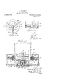
- Figure 1 is a central vertical sectlon of an electrical drink mixer embodying my inventlon;
- Fig. 2 is a plan view of the under side of the rotor employed in the drink mixer shown in Fig. 1;
- Fig. 3 is a plan view of the stator shown in Fig. 1;
- Fig. 4 is a section taken on the line 4-4 of Fig. 2;
- Fig. 5 is a diagram showing the circuit of the induction motor illustrated in Fig. 1;
- Fig. 6 is a central vertical section of the preferred form of my invention.
- Fig. 7 is a plan view of the rotor represented in Fig. 6; i
- Fig. 8 is a vertical section taken on line 8-8 of Fig. 7
- Fig. 9 is a plan .view of the stator employed in the drink mixer shown in Fig. 6;
- Fig. 10 is" a diagram showing the circuit.
- Fig. 12 IS an 'elevatlon of said switch showlng the swltch elements in normal or circuit-opening position, certain parts being shown in vertical section;
- Fig. 13 is a central vertical section of a.
- the rotor is rotatably mounted in a removable device resiliently held in the'bottom of'the liquid container which may be of glass or other dielectric material;
- Fig. 14 is a plan view of a further modification in which the rotor is so constructed as to perform the function of an agitator;
- Fig, 15 is a section taken on the line 15-15 of Fig.14; J
- Fig. 16 is a sectiontaken on the line 16-16 of Fig. 14.
- the rotor consists in this particular instance of asolid metalplate 33 having twenty three copper bars 34, rectangular in cross section, inserted in channels cut in the lower face thereof, such channels being angularly related to a radius of said rotor. Said inserted copper bars are short-circuited at their outer and inner ends by the copper bands 36 and 37, the former being arranged on the periphery of the rotor plate and the latter being inset in the face thereof.
- the stator 38 in the'present instance, consists of a laminated ring having twelve upstanding pole pieces 39, the latter being milled out of the upper face of said ring.
- the windings of the stator shown at 40 may be of any suitable type such for example as chain windings.
- an inductance L and resistance R located within the casing 41 which encloses the stator are connected in series with the respective stator windings A, B, as indicated in Fig. 5, and by suitable leads not shown in Fig. 1, the several elements are connected to a source of alternating current G.
- N0 novelty is claimed for the particular form of induction-motor shown in Figure 1, and as will be obvious any other suitable type of alternatingcurrent motor may be substituted therefor without departing from the spirit of my invention, for example, a rotaryfield motor having a rotor consisting of a solid ring which carries no closed circuits as shown at and 70 in Figs. 13 and 14 hereinafter described.
- Fig. 6 I show the preferred embodiment of m invention in which the casing 43 is provide with a deeper centrally arranged depression 44 adapted to receive 'the hollow base 23 of the container.
- the rotor 45 is rotatably mounted in said hollow base and the lower end of its shaft 29' is provided with a cylindrical depression 28 for receiving the steel ball 25, said shaft being journalled as in the arrangement shown in Fig. 1 in said base and an agitator 30 being secured to said shaft by the cap 31 threaded to the upper end thereof or in any other suitable manner.
- the rotor 45 as shown in Fig. 7 consists of a ring of magnetic metal having in the present instance twenty three peripheral slots 46 for receiving conducting bars 46 and is attached to a spider 47 to which the shaft 29 is rigidly secured.
- the conducting bars, and their short-circuiting rings 48, together with the spider and its hub 49, which are of aluminum, are cast integrally in and around the ring 45, and the periphery of the latter is then machined.
- the stator '49 consists of a laminated ring having in the present instance twelve narrow deep radial slots 50 carrying any suitable type of winding 40, such for example, as a skein winding.
- the windings 40 consisting of the parts A and B connected in the manner shown are designed to eliminate the phasesplitting inductance L and resistance R, shown in Fig. 5, the winding A being of relatively high inductance and relatively low resistance and the winding B of relatively low inductance and relatively high resistance.
- windings may be designed to have these characteristics in a number of different ways, I prefer, as indicated, to arrange them as follows, viz., the winding B consists of wire of smaller diameter than the winding A, is of material having a higher specific resistance, has fewer turns, and is -located in the top portion of the slot, and said slot as shown has a relatively wide opening. Extending across each slot, and separating the two sets of windings is a plate of magnetic material 51 which by closing the magnetic circuit of the winding A increases the inductance of the latter. The windings are maintained in their slots by the nonmagnetic plates 52.
- an automatic switch mounted on a base53, said switch being operable by said hollow base 23 when the latter is placed in or removed from the depression 44 of the casing. While it willbe clear that various forms of switches may be employed for closing the circuit of the stator when the liquid container is placed with its rotor in co-operative relation with the stator, I have shown in Fig. 6 a simple non-arcing switch which is effective for this purpose. Said switch consists of the spring clips 54, 54 mounted on the base 53 and constructed to receive the circuit closer 55 slidably mounted on the stem 56 and located between the collars 57 and 58 which are fixedly secured to said stem.
- a helical spring 59 Interposed between the circuit closer 55 and the collar 58 is a helical spring 59 and a' similar spring 60 is arranged between said collar 58 and the upstanding boss 60'.
- the cap 61 is attached by the screw 62 to the upper end of the stem 56 and is guided by the tubular casing 63 which enclosesthe switch members, a bridge 64 passing across the top of said casing 63 servmg as a guide for the stem 56.
- the high inductance, low resistance winding A and the low inductance, high resistance winding B are connected in parallel with the source of alternating current G, said source being connected thereto at the points a, e.
- the conductor 7) connected to the windings at the point a and the conductor a connected to the socket 66' pass through an opening (not shown) in the casing 43. and are connected tothe terminals of a. suitable source G of alternating current, usually being'connected thereto through a plug and socket of the ordinary lighting system.
- the conductor d connects the socket 66 with the stator windings at the point e. 7
- a tripod of spring material Arranged within said vessel and resting on the bottom thereof is a tripod of spring material having its feet 69 sprung by the elasticity thereof against the inner sides of said vessel so as to form a firm supporting member for the rotor 70 placed in the plane of the stator 49.
- the radial arms 68 of the tripod carry a centrally arranged bearing 71 for the shaft 72 of the rotor, the latter carrying the agitator 30 secured thereto by the cap 31 threaded'to said shaft.
- the feet of the tripod extend upwardly aswell as downwardly from the radial arms 68 thereof, and the lower end of the shaft 72 is provided with a point 73 which rests on the bottom of the container, although it will be obvious that other arrangements may be employed for positioning the rotor in the receptacle and for affording a suitable bearing for the same on the bottom thereof.
- the rotor consists of a solid ring connected by the spokes 74 to a central hub rigidly attached to the shaft 72, although, as will beapparent, said rotor may be a solid metal disc.
- Figs. 14 to. 16 inclusive I show a further modification wherein the rotor 70' consists of a ring connected to the-central hub 75 by the arms 76, which as indicated in Fig. 16,-are inclined to the horizontal and therefore perform the function of an agitator.
- the shaft 7 2' will preferably terminate at the upper end of the bearing 71. 7
- An electrical drink mixer comprising in combination a liquid container, a hollow base detachably secured thereto, a rotor ro--.
- An electrical drink mixer comprising in combination a liquid container having its bottom provided with a centrally disposed internally threaded opening, a hollow base provided with a centrally disposed externally threaded boss arranged to be threaded into said opening, a vertical shaft journalled in said base and extending upwardly into said container, an agitator carried by said shaft and disposed within said ber, 1921.
- An electrical drink mixer comprising 1 in combination a liquidcontainer, a hollow base detachably secured thereto, a rotor ro-- in combination a liquid container, an agitator disposed thereln, a rotor, means attaching said agitator to said rotor, a casing having a centrally disposed depression for receiving said container, a stator in said casing, said stator being arranged in the plane of said rotor, and an automatic switch for controlling the circuit of said stator, said switch being located in thebottom of said casing and being operable by said container when the latter is placed in or removed from said depression.
- An electrical drink mixer comprising in combination a liquid container, an agitator disposed therein, a rotor, means attaching said agitator to said rotor, a casing having a centrally disposed depression for receiving said container, a stator in said casing, said stator being in co-operative relation with said rotor, and an automatic switch for controlling the circuit of said stator, said switch being located in the bottom of said casing and being operable by said container when the latter is placed in or removed from said depression.
Landscapes
- Engineering & Computer Science (AREA)
- Chemical & Material Sciences (AREA)
- Chemical Kinetics & Catalysis (AREA)
- Power Engineering (AREA)
- Mechanical Engineering (AREA)
- Food Science & Technology (AREA)
- Mixers Of The Rotary Stirring Type (AREA)
Description
F. A. STAINBROOK. ELECTRICAL DRINK MIXER.
APPLICATION man 050.22, 1921.
1,420,773. PatentedJune27,
4 SHEETSSHEE F. A. 'STAINBROOK.
ELECTRICALDRINK MIXER. APPLICATION FILED DEC-22, 1921.
Patented June 27 1922.
4 SHEETS-SHEET 2.
F. A. STAINBROOK.
ELECTRICAL DRINK MIXER.
APPLICATION FlLED 050.22, 1921.
1,420,773 Patented June 27, 1922'.
4 SHEETS-SHEET 3.
F. A. STAINBROOK.
ELECTRICAL DRINK MIXER.
APPLICATION FILED DEC,22, 1921.
1,420,773. Patented June 27, 1922.
4 SHEETS-SHEET 4.
UNITED STATES PATENT OFFICE.
FOREST A. STAINBROOK. OF BOSTON, MASSACHUSETTS, ASSIGNOR TO MAGNETIC DRINK MIXER COMPANY A CORPORATION OF MASSACHUSETTS.
ELECTRICAL DRINK MIXER.
' Specification of Letters Patent.
Patented June 27, 1922.
Application filed December 22, 1921. Serial no. 524,150.
. lowing is a specification.
My invention relates to electrical drink mixers of the alternating current motor type wherein there is no mechanical connection between the driving element of the agitator disposed in the liquid receptacle and the outside energizing element,
The object of my invention is to provide an electrical drink mixer having the agi tator driving-element within the hollow base of the liquid container whereby said container may be removed from the drivingelement energizing means for the purpose of emptying said receptacle Without breaking a mechanical connection.
A further object is to provide such drink mixer wherein the act of placing the container in the casing which contains the energizing element will close the circuit of the latter, and the removal of said container therefrom automatically will break said circuit.
Another object is to provide a drink mixer having a container which may be readily removed for cleansing'from the agitator and its operating means.-
Further objects will hereinafter more fully appear from the following detailed description taken in connection with the accompanying drawings.
With the foregoing objects in view my in vention comprises as its salient features a liquid container having a hollow base detachably secured thereto and enclosing a rotatably-mounted alternating-'current-motor rotor operatively connected with an agitator disposed within said container; and also an automatic switch so located that the placing of said rotor in operative position with respect to its co-operating stator will close the circuit of the latter, and the removal of said rotor from such position will open said circuit.
In the drawings which accompany and form a part of this specification,-
Figure 1 is a central vertical sectlon of an electrical drink mixer embodying my inventlon;
Fig. 2 is a plan view of the under side of the rotor employed in the drink mixer shown in Fig. 1;
Fig. 3 is a plan view of the stator shown in Fig. 1;
Fig. 4 is a section taken on the line 4-4 of Fig. 2;
Fig. 5 is a diagram showing the circuit of the induction motor illustrated in Fig. 1;
Fig. 6 is a central vertical section of the preferred form of my invention;
Fig. 7 is a plan view of the rotor represented in Fig. 6; i
Fig. 8 is a vertical section taken on line 8-8 of Fig. 7
Fig. 9 is a plan .view of the stator employed in the drink mixer shown in Fig. 6;
Fig. 10 is" a diagram showing the circuit.
ments in intermediate position just before the circuit is broken, certain parts being shown in central vertical section;
Fig. 12 IS an 'elevatlon of said switch showlng the swltch elements in normal or circuit-opening position, certain parts being shown in vertical section;
Fig. 13 is a central vertical section of a.
modification wherein the rotor is rotatably mounted in a removable device resiliently held in the'bottom of'the liquid container which may be of glass or other dielectric material;
Fig. 14 is a plan view of a further modification in which the rotor is so constructed as to perform the function of an agitator;
Fig, 15 is a section taken on the line 15-15 of Fig.14; J
Fig. 16 is a sectiontaken on the line 16-16 of Fig. 14.
In the particular drawings selected for more fully disclosing my .inventi0n'20 represents a liquid container having its bottom provided with an internally-threaded opening 21 arranged to receive the upstanding exteriorly-threaded boss 22 formed integral with the hollow base 23. Rotatably mounted in said hollow base is the rotor of an-alternat1ng-current-motor,-such as an inductlonmotor rotor 24;, a steel ball 25 being interconsisting of two oppositely inclined blades,
. is carried by said shaft, said blades being shown in the present instance as clamped between the shaft and the cap 31,alth0ugh it will be understood that any suitable means may be employed for attaching the agitator to its shaft. Preferably ball bearings 32, 32 are employed for journalling the shaft 29 in the hollow base. I
As shown in Fig. 2, the rotor consists in this particular instance of asolid metalplate 33 having twenty three copper bars 34, rectangular in cross section, inserted in channels cut in the lower face thereof, such channels being angularly related to a radius of said rotor. Said inserted copper bars are short-circuited at their outer and inner ends by the copper bands 36 and 37, the former being arranged on the periphery of the rotor plate and the latter being inset in the face thereof.
The stator 38, in the'present instance, consists of a laminated ring having twelve upstanding pole pieces 39, the latter being milled out of the upper face of said ring.
The windings of the stator shown at 40 may be of any suitable type such for example as chain windings. To secure the necessary phase displacement an inductance L and resistance R, located within the casing 41 which encloses the stator are connected in series with the respective stator windings A, B, as indicated in Fig. 5, and by suitable leads not shown in Fig. 1, the several elements are connected to a source of alternating current G.
As will be obvious when the base 23 of the liquid container is placed in the centrally disposed depression 42 in the upper face of the casing 41, the energization of the stator will cause the rotor to revolve rapidly and the agitator will thoroughly stir the contents of the container.
N0 novelty is claimed for the particular form of induction-motor shown in Figure 1, and as will be obvious any other suitable type of alternatingcurrent motor may be substituted therefor without departing from the spirit of my invention, for example, a rotaryfield motor having a rotor consisting of a solid ring which carries no closed circuits as shown at and 70 in Figs. 13 and 14 hereinafter described.
By means of the arrangement described in Figure 1 the rotor is so placed that it cannot be injured by the contents of the container 20, and when it is desired to cleanse the device, it is necessary only to unscrew said container from its base thereby exposing the agitator 30.
In Fig. 6 I show the preferred embodiment of m invention in which the casing 43 is provide with a deeper centrally arranged depression 44 adapted to receive 'the hollow base 23 of the container. The rotor 45 is rotatably mounted in said hollow base and the lower end of its shaft 29' is provided with a cylindrical depression 28 for receiving the steel ball 25, said shaft being journalled as in the arrangement shown in Fig. 1 in said base and an agitator 30 being secured to said shaft by the cap 31 threaded to the upper end thereof or in any other suitable manner.
The rotor 45 as shown in Fig. 7 consists of a ring of magnetic metal having in the present instance twenty three peripheral slots 46 for receiving conducting bars 46 and is attached to a spider 47 to which the shaft 29 is rigidly secured. Preferably the conducting bars, and their short-circuiting rings 48, together with the spider and its hub 49, which are of aluminum, are cast integrally in and around the ring 45, and the periphery of the latter is then machined.
It will be understood of course that my invention is not limited to a rotor of this type. The stator '49 consists of a laminated ring having in the present instance twelve narrow deep radial slots 50 carrying any suitable type of winding 40, such for example, as a skein winding. In the present instance the windings 40, consisting of the parts A and B connected in the manner shown are designed to eliminate the phasesplitting inductance L and resistance R, shown in Fig. 5, the winding A being of relatively high inductance and relatively low resistance and the winding B of relatively low inductance and relatively high resistance.
While said windings may be designed to have these characteristics in a number of different ways, I prefer, as indicated, to arrange them as follows, viz., the winding B consists of wire of smaller diameter than the winding A, is of material having a higher specific resistance, has fewer turns, and is -located in the top portion of the slot, and said slot as shown has a relatively wide opening. Extending across each slot, and separating the two sets of windings is a plate of magnetic material 51 which by closing the magnetic circuit of the winding A increases the inductance of the latter. The windings are maintained in their slots by the nonmagnetic plates 52.
Removably attached to the bottom of the casing 43 is an automatic switch mounted on a base53, said switch being operable by said hollow base 23 when the latter is placed in or removed from the depression 44 of the casing. While it willbe clear that various forms of switches may be employed for closing the circuit of the stator when the liquid container is placed with its rotor in co-operative relation with the stator, I have shown in Fig. 6 a simple non-arcing switch which is effective for this purpose. Said switch consists of the spring clips 54, 54 mounted on the base 53 and constructed to receive the circuit closer 55 slidably mounted on the stem 56 and located between the collars 57 and 58 which are fixedly secured to said stem. Interposed between the circuit closer 55 and the collar 58 is a helical spring 59 and a' similar spring 60 is arranged between said collar 58 and the upstanding boss 60'. The cap 61 is attached by the screw 62 to the upper end of the stem 56 and is guided by the tubular casing 63 which enclosesthe switch members, a bridge 64 passing across the top of said casing 63 servmg as a guide for the stem 56. I
Normally when the container is not rest ing on the cap 61, the parts have the positions shown in Fig. 12, the .pr'ing 60, acting between the boss 60 and the collar 58 forcing the stem 56 to its uppermost position, the upward movement ofsaidstem being limited by the washer 57 and the guide 64.
' When the cap 61 is depressed, as by placing the container in the receptacle 4.4 of the casing the circuit closer 55 is forced downwardly between the clips 54, 54 and thereby closes the circuit of the stator by way of the plugs 65, 65 upstanding from the base 53 and electrically connected with the clips 54, 54, suitable'sockets 66, 66' being inserted in the bottom of the casing for receiving said plugs.
As indicated in Fig. 10 the high inductance, low resistance winding A and the low inductance, high resistance winding B are connected in parallel with the source of alternating current G, said source being connected thereto at the points a, e.
The conductor 7) connected to the windings at the point a and the conductor a connected to the socket 66' pass through an opening (not shown) in the casing 43. and are connected tothe terminals of a. suitable source G of alternating current, usually being'connected thereto through a plug and socket of the ordinary lighting system. The conductor d connects the socket 66 with the stator windings at the point e. 7
It will be noted that in normal position neither of the springs 59, 60 is under comcondition. As soon as the container is lifted spring 60 co-operating between the boss 60.
and collar 58 will raise the stem 56 a short distance, and compress the spring 59 between the collar 58 and circuit closer 55, the latter being held between the spring clips 54. As soon as the pressure exerted by the spring 59 againstthe under side of'the circuit closer is suflicient to overcome the grip on the latter of the spring clips, said circuit closer is shot rapidly upwardly against the collar 57, and the spring 60 raises t e stem to its normal position shown in Fi 12. The position of the parts immediately after the weight of the container is removed from the in Fig. 13 in which 67 represents a mixing vessel, which may be of glass or other dielectric material, placed in the depression 44 of the casing 43 and actuating the automatic switch in the same manner as the container 20 of Fig. 6. Arranged within said vessel and resting on the bottom thereof is a tripod of spring material having its feet 69 sprung by the elasticity thereof against the inner sides of said vessel so as to form a firm supporting member for the rotor 70 placed in the plane of the stator 49. In the present instance the radial arms 68 of the tripod carry a centrally arranged bearing 71 for the shaft 72 of the rotor, the latter carrying the agitator 30 secured thereto by the cap 31 threaded'to said shaft. Preferably the feet of the tripod extend upwardly aswell as downwardly from the radial arms 68 thereof, and the lower end of the shaft 72 is provided with a point 73 which rests on the bottom of the container, although it will be obvious that other arrangements may be employed for positioning the rotor in the receptacle and for affording a suitable bearing for the same on the bottom thereof.
As shown in Fig. 13 the rotor consists of a solid ring connected by the spokes 74 to a central hub rigidly attached to the shaft 72, although, as will beapparent, said rotor may be a solid metal disc..
In Figs. 14 to. 16 inclusive I show a further modification wherein the rotor 70' consists of a ring connected to the-central hub 75 by the arms 76, which as indicated in Fig. 16,-are inclined to the horizontal and therefore perform the function of an agitator. In this case, the shaft 7 2' will preferably terminate at the upper end of the bearing 71. 7
No claim is made herein to the automatic hon-arcing switch shown in Figs. 6, 11, and
shown in Figs. 7, 8, and 9, or to the modification shown in Figs. 13, 14, 15, and 16 in which the rotor is held resiliently in the mixing vessel, as these inventions form the subject matter -of my co-pending applications Ser. Nos. 559,554, 559,555, and 559,556, respectively, filed May 9, 1922.
Having thus described various illustrative embodiments of my invention without however limiting the same thereto, what I claim and desire to secure by Letters Patent is 2- 1. An electrical drink mixer comprising in combination a liquid container, a hollow base detachably secured thereto, a rotor ro--.
tatably mounted in said base, a shaft carried by said rotor and extending upwardly into said container, an agitator carried by said shaft and disposed within said container, a casing having a centrally disposed depression arranged to receive said hollow base, a stator in said casing, and an automatic switch for controlling the circuit of said stator, said switch being located in the bottom of said casing and being operable by said hollow base when the latter is placed in or removed from said depression.
3. An electrical drink mixer comprising in combination a liquid container having its bottom provided with a centrally disposed internally threaded opening, a hollow base provided with a centrally disposed externally threaded boss arranged to be threaded into said opening, a vertical shaft journalled in said base and extending upwardly into said container, an agitator carried by said shaft and disposed within said ber, 1921.
container, a rotor rotatably mounted in said base and secured-to the lower end-of said shaft, a casing for supporting said hollow; 3
base, and a stator enclosed within said casing and arranged in co-operative relation with said rotor.
4. An electrical drink mixer comprising 1 in combination a liquidcontainer, a hollow base detachably secured thereto, a rotor ro-- in combination a liquid container, an agitator disposed thereln, a rotor, means attaching said agitator to said rotor, a casing having a centrally disposed depression for receiving said container, a stator in said casing, said stator being arranged in the plane of said rotor, and an automatic switch for controlling the circuit of said stator, said switch being located in thebottom of said casing and being operable by said container when the latter is placed in or removed from said depression.
6. An electrical drink mixer comprising in combination a liquid container, an agitator disposed therein, a rotor, means attaching said agitator to said rotor, a casing having a centrally disposed depression for receiving said container, a stator in said casing, said stator being in co-operative relation with said rotor, and an automatic switch for controlling the circuit of said stator, said switch being located in the bottom of said casing and being operable by said container when the latter is placed in or removed from said depression.
In testimony whereof, I have hereunto subscribed my name this 20 day of Decem- FOREST A. STAIN-BROOK.
Priority Applications (2)
| Application Number | Priority Date | Filing Date | Title |
|---|---|---|---|
| US524150A US1420773A (en) | 1921-12-22 | 1921-12-22 | Electrical drink mixer |
| US559556A US1420774A (en) | 1921-12-22 | 1922-05-09 | Electrical drink mixer |
Applications Claiming Priority (1)
| Application Number | Priority Date | Filing Date | Title |
|---|---|---|---|
| US524150A US1420773A (en) | 1921-12-22 | 1921-12-22 | Electrical drink mixer |
Publications (1)
| Publication Number | Publication Date |
|---|---|
| US1420773A true US1420773A (en) | 1922-06-27 |
Family
ID=24087973
Family Applications (1)
| Application Number | Title | Priority Date | Filing Date |
|---|---|---|---|
| US524150A Expired - Lifetime US1420773A (en) | 1921-12-22 | 1921-12-22 | Electrical drink mixer |
Country Status (1)
| Country | Link |
|---|---|
| US (1) | US1420773A (en) |
Cited By (51)
| Publication number | Priority date | Publication date | Assignee | Title |
|---|---|---|---|---|
| US2506886A (en) * | 1948-04-19 | 1950-05-09 | Automatic Magnetic Agitators L | Magnetic drive agitator |
| US2610663A (en) * | 1947-08-29 | 1952-09-16 | Jerome L Murray | Fruit reamer |
| US2691124A (en) * | 1949-03-12 | 1954-10-05 | Gen Mills Inc | Electric motor and switch |
| US2782452A (en) * | 1950-11-27 | 1957-02-26 | G M Lab Inc | Floor polishing and scrubbing machine |
| US2782997A (en) * | 1953-03-18 | 1957-02-26 | Nat Rubber Machinery Co | Garbage disposal apparatus |
| US2810556A (en) * | 1955-03-14 | 1957-10-22 | Tormag Transmissions Ltd | Agitators for fluid cooling tanks and the like |
| US2867420A (en) * | 1957-05-10 | 1959-01-06 | Donald M Potts | Electric double boiler |
| US3140079A (en) * | 1960-02-18 | 1964-07-07 | Baermann Max | Magnetic drive |
| EP0040328A1 (en) * | 1980-05-16 | 1981-11-25 | Dürr-Dental GmbH & Co. KG | Developing apparatus with stirring facility |
| EP0045434A1 (en) * | 1980-07-31 | 1982-02-10 | Agfa-Gevaert AG | Device for developing photographic emulsion carriers |
| US4465377A (en) * | 1983-06-07 | 1984-08-14 | Techne Corporation | Magnetic stirrer apparatus with guided, floating stirrer |
| US5676462A (en) * | 1996-04-16 | 1997-10-14 | Eastman Kodak Company | Suspended magnetic impeller/baffle apparatus for liquid |
| WO2000041607A1 (en) | 1999-01-12 | 2000-07-20 | Island Oasis Frozen Cocktail Co., Inc. | Food processing apparatus including magnetic drive |
| US6095677A (en) * | 1999-01-12 | 2000-08-01 | Island Oasis Frozen Cocktail Co., Inc. | Magnetic drive blender |
| US6712497B2 (en) * | 2001-05-22 | 2004-03-30 | Shurflo Pump Manufacturing Co., Inc. | Material processing appliance and associated magnetic drive unit |
| WO2004043213A1 (en) | 2002-11-12 | 2004-05-27 | Island Oasis Frozen Cocktail Company, Inc. | Food processing apparatus including magnetic drive |
| US20040151065A1 (en) * | 2003-01-30 | 2004-08-05 | Scientific Industries, Inc. | Magnetic stirring apparatus having low rotational speeds |
| US20050002275A1 (en) * | 2003-07-02 | 2005-01-06 | Spx Corporation | Axial-pumping impeller apparatus and method for magnetically-coupled mixer |
| US20050002274A1 (en) * | 2001-10-03 | 2005-01-06 | Terentiev Alexandre N. | Mixing bag or vessel having a receiver for a fluid-agitating element |
| US20070036027A1 (en) * | 2005-07-29 | 2007-02-15 | Meier Hans P | Magnetic agitator |
| US20090303832A1 (en) * | 2005-03-17 | 2009-12-10 | Sulzer Pumpen Ag | Agitator |
| US20100046323A1 (en) * | 2007-02-08 | 2010-02-25 | Linsheng Walter Tien | Magnetic Stirring Devices and Methods |
| US20100157725A1 (en) * | 2007-02-21 | 2010-06-24 | Terentiev Alexandre N | Roller Bearing for a Fluid-Agitating Element and Associated Vessel |
| US20100214867A1 (en) * | 2009-02-24 | 2010-08-26 | Karkos Jr John F | Magnetic drive for food processing apparatus |
| CN102670096A (en) * | 2012-05-09 | 2012-09-19 | 美的集团有限公司 | a blender |
| JP2013150735A (en) * | 2012-01-26 | 2013-08-08 | Fmi Corp | Mixing food processor |
| US20140334249A1 (en) * | 2013-05-08 | 2014-11-13 | Roxi Group, Inc. | Beverage mixing, storing and dispensing apparatus |
| US20150367302A1 (en) * | 2013-01-23 | 2015-12-24 | Ge Healthcare Bio-Sciences Ab | Magnetic agitator mixing system and an agitator mixing stand |
| US20180154320A1 (en) * | 2015-05-07 | 2018-06-07 | Ika-Werke Gmbh & Co. Kg | Magnetic coupling and stirring device with magnetic coupling |
| CN109691909A (en) * | 2017-10-23 | 2019-04-30 | 佛山市顺德区美的电热电器制造有限公司 | Disk, stirring toolbox and food cooking machine |
| JP2020500597A (en) * | 2016-12-05 | 2020-01-16 | ミロ アプライアンセス ユーエービーMillo Appliances, Uab | Food and beverage processing equipment with magnetic coupling |
| US11330938B2 (en) * | 2019-11-06 | 2022-05-17 | Whirlpool Corporation | Non-contact magnetic coupler for food processing appliance having small brushless permanent magnet motor |
| US11612865B1 (en) | 2022-05-13 | 2023-03-28 | Sharkninja Operating Llc | Agitator for a carbonation system |
| US11634314B1 (en) | 2022-11-17 | 2023-04-25 | Sharkninja Operating Llc | Dosing accuracy |
| US11647860B1 (en) | 2022-05-13 | 2023-05-16 | Sharkninja Operating Llc | Flavored beverage carbonation system |
| US11738988B1 (en) | 2022-11-17 | 2023-08-29 | Sharkninja Operating Llc | Ingredient container valve control |
| US11745996B1 (en) | 2022-11-17 | 2023-09-05 | Sharkninja Operating Llc | Ingredient containers for use with beverage dispensers |
| US11751585B1 (en) | 2022-05-13 | 2023-09-12 | Sharkninja Operating Llc | Flavored beverage carbonation system |
| US11871867B1 (en) | 2023-03-22 | 2024-01-16 | Sharkninja Operating Llc | Additive container with bottom cover |
| US11925287B1 (en) | 2023-03-22 | 2024-03-12 | Sharkninja Operating Llc | Additive container with inlet tube |
| US12005404B2 (en) | 2022-08-22 | 2024-06-11 | Sharkninja Operating Llc | Beverage carbonation system flow control |
| US12005408B1 (en) | 2023-04-14 | 2024-06-11 | Sharkninja Operating Llc | Mixing funnel |
| US12017192B1 (en) | 2023-06-16 | 2024-06-25 | Sharkninja Operating Llc | Carbonation mixing nozzles |
| US12084334B2 (en) | 2022-11-17 | 2024-09-10 | Sharkninja Operating Llc | Ingredient container |
| US12096880B2 (en) | 2022-05-13 | 2024-09-24 | Sharkninja Operating Llc | Flavorant for beverage carbonation system |
| US12103840B2 (en) | 2022-11-17 | 2024-10-01 | Sharkninja Operating Llc | Ingredient container with sealing valve |
| US12116257B1 (en) | 2023-03-22 | 2024-10-15 | Sharkninja Operating Llc | Adapter for beverage dispenser |
| US12213617B2 (en) | 2022-05-13 | 2025-02-04 | Sharkninja Operating Llc | Flavored beverage carbonation process |
| USD1091308S1 (en) | 2022-12-23 | 2025-09-02 | Sharkninja Operating Llc | Ingredient container |
| USD1092208S1 (en) | 2022-12-23 | 2025-09-09 | Sharkninja Operating Llc | Cap of ingredient container |
| US12539500B2 (en) | 2022-08-31 | 2026-02-03 | Sharkninja Operating Llc | Additive containers |
-
1921
- 1921-12-22 US US524150A patent/US1420773A/en not_active Expired - Lifetime
Cited By (67)
| Publication number | Priority date | Publication date | Assignee | Title |
|---|---|---|---|---|
| US2610663A (en) * | 1947-08-29 | 1952-09-16 | Jerome L Murray | Fruit reamer |
| US2506886A (en) * | 1948-04-19 | 1950-05-09 | Automatic Magnetic Agitators L | Magnetic drive agitator |
| US2691124A (en) * | 1949-03-12 | 1954-10-05 | Gen Mills Inc | Electric motor and switch |
| US2782452A (en) * | 1950-11-27 | 1957-02-26 | G M Lab Inc | Floor polishing and scrubbing machine |
| US2782997A (en) * | 1953-03-18 | 1957-02-26 | Nat Rubber Machinery Co | Garbage disposal apparatus |
| US2810556A (en) * | 1955-03-14 | 1957-10-22 | Tormag Transmissions Ltd | Agitators for fluid cooling tanks and the like |
| US2867420A (en) * | 1957-05-10 | 1959-01-06 | Donald M Potts | Electric double boiler |
| US3140079A (en) * | 1960-02-18 | 1964-07-07 | Baermann Max | Magnetic drive |
| EP0040328A1 (en) * | 1980-05-16 | 1981-11-25 | Dürr-Dental GmbH & Co. KG | Developing apparatus with stirring facility |
| EP0045434A1 (en) * | 1980-07-31 | 1982-02-10 | Agfa-Gevaert AG | Device for developing photographic emulsion carriers |
| US4465377A (en) * | 1983-06-07 | 1984-08-14 | Techne Corporation | Magnetic stirrer apparatus with guided, floating stirrer |
| US5676462A (en) * | 1996-04-16 | 1997-10-14 | Eastman Kodak Company | Suspended magnetic impeller/baffle apparatus for liquid |
| WO2000041607A1 (en) | 1999-01-12 | 2000-07-20 | Island Oasis Frozen Cocktail Co., Inc. | Food processing apparatus including magnetic drive |
| US6095677A (en) * | 1999-01-12 | 2000-08-01 | Island Oasis Frozen Cocktail Co., Inc. | Magnetic drive blender |
| US6210033B1 (en) | 1999-01-12 | 2001-04-03 | Island Oasis Frozen Cocktail Co., Inc. | Magnetic drive blender |
| US6336603B1 (en) | 1999-01-12 | 2002-01-08 | Island Oasis Frozen Cocktail Company, Inc. | Food processing apparatus including magnetic drive |
| US6793167B2 (en) | 1999-01-12 | 2004-09-21 | Island Oasis Cocktail Company, Inc. | Food processing apparatus including magnetic drive |
| US6712497B2 (en) * | 2001-05-22 | 2004-03-30 | Shurflo Pump Manufacturing Co., Inc. | Material processing appliance and associated magnetic drive unit |
| US7481572B2 (en) * | 2001-10-03 | 2009-01-27 | Levtech, Inc. | Mixing bag or vessel having a receiver for a fluid-agitating element |
| US20050002274A1 (en) * | 2001-10-03 | 2005-01-06 | Terentiev Alexandre N. | Mixing bag or vessel having a receiver for a fluid-agitating element |
| WO2004043213A1 (en) | 2002-11-12 | 2004-05-27 | Island Oasis Frozen Cocktail Company, Inc. | Food processing apparatus including magnetic drive |
| US6962433B2 (en) * | 2003-01-30 | 2005-11-08 | Scientific Industries, Inc. | Magnetic stirring apparatus having low rotational speeds |
| US20040151065A1 (en) * | 2003-01-30 | 2004-08-05 | Scientific Industries, Inc. | Magnetic stirring apparatus having low rotational speeds |
| US20050002275A1 (en) * | 2003-07-02 | 2005-01-06 | Spx Corporation | Axial-pumping impeller apparatus and method for magnetically-coupled mixer |
| US7168848B2 (en) * | 2003-07-02 | 2007-01-30 | Spx Corporation | Axial-pumping impeller apparatus and method for magnetically-coupled mixer |
| US20090303832A1 (en) * | 2005-03-17 | 2009-12-10 | Sulzer Pumpen Ag | Agitator |
| US20070036027A1 (en) * | 2005-07-29 | 2007-02-15 | Meier Hans P | Magnetic agitator |
| US8128277B2 (en) * | 2005-07-29 | 2012-03-06 | Zeta Biopharma Gmbh | Magnetic agitator |
| US20100046323A1 (en) * | 2007-02-08 | 2010-02-25 | Linsheng Walter Tien | Magnetic Stirring Devices and Methods |
| US20100157725A1 (en) * | 2007-02-21 | 2010-06-24 | Terentiev Alexandre N | Roller Bearing for a Fluid-Agitating Element and Associated Vessel |
| US20100214867A1 (en) * | 2009-02-24 | 2010-08-26 | Karkos Jr John F | Magnetic drive for food processing apparatus |
| EP3117716A1 (en) | 2009-02-24 | 2017-01-18 | Island Oasis Frozen Cocktail Co. Inc. | Magnetic drive for food processing apparatus |
| US8282268B2 (en) * | 2009-02-24 | 2012-10-09 | Island Oasis Frozen Cocktail Co., Inc. | Magnetic drive for food processing apparatus |
| EP2400854B1 (en) * | 2009-02-24 | 2016-05-25 | Island Oasis Frozen Cocktail Co. Inc. | Magnetic drive for food processing apparatus |
| JP2013150735A (en) * | 2012-01-26 | 2013-08-08 | Fmi Corp | Mixing food processor |
| CN102670096B (en) * | 2012-05-09 | 2015-08-19 | 美的集团股份有限公司 | A kind of mixer |
| CN102670096A (en) * | 2012-05-09 | 2012-09-19 | 美的集团有限公司 | a blender |
| US20150367302A1 (en) * | 2013-01-23 | 2015-12-24 | Ge Healthcare Bio-Sciences Ab | Magnetic agitator mixing system and an agitator mixing stand |
| US20140334249A1 (en) * | 2013-05-08 | 2014-11-13 | Roxi Group, Inc. | Beverage mixing, storing and dispensing apparatus |
| US20180154320A1 (en) * | 2015-05-07 | 2018-06-07 | Ika-Werke Gmbh & Co. Kg | Magnetic coupling and stirring device with magnetic coupling |
| JP2020500597A (en) * | 2016-12-05 | 2020-01-16 | ミロ アプライアンセス ユーエービーMillo Appliances, Uab | Food and beverage processing equipment with magnetic coupling |
| CN109691909A (en) * | 2017-10-23 | 2019-04-30 | 佛山市顺德区美的电热电器制造有限公司 | Disk, stirring toolbox and food cooking machine |
| US11330938B2 (en) * | 2019-11-06 | 2022-05-17 | Whirlpool Corporation | Non-contact magnetic coupler for food processing appliance having small brushless permanent magnet motor |
| US12082745B2 (en) | 2019-11-06 | 2024-09-10 | Whirlpool Corporation | Non-contact magnetic coupler for food processing appliance having small brushless permanent magnet motor |
| US11612865B1 (en) | 2022-05-13 | 2023-03-28 | Sharkninja Operating Llc | Agitator for a carbonation system |
| US12213617B2 (en) | 2022-05-13 | 2025-02-04 | Sharkninja Operating Llc | Flavored beverage carbonation process |
| US11647860B1 (en) | 2022-05-13 | 2023-05-16 | Sharkninja Operating Llc | Flavored beverage carbonation system |
| US12096880B2 (en) | 2022-05-13 | 2024-09-24 | Sharkninja Operating Llc | Flavorant for beverage carbonation system |
| US11751585B1 (en) | 2022-05-13 | 2023-09-12 | Sharkninja Operating Llc | Flavored beverage carbonation system |
| US12005404B2 (en) | 2022-08-22 | 2024-06-11 | Sharkninja Operating Llc | Beverage carbonation system flow control |
| US12539500B2 (en) | 2022-08-31 | 2026-02-03 | Sharkninja Operating Llc | Additive containers |
| US12122661B2 (en) | 2022-11-17 | 2024-10-22 | Sharkninja Operating Llc | Ingredient container valve control |
| US12006202B1 (en) | 2022-11-17 | 2024-06-11 | Sharkninja Operating Llc | Ingredient container valve control |
| US12410048B2 (en) | 2022-11-17 | 2025-09-09 | Sharkninja Operating Llc | Ingredient container |
| US11634314B1 (en) | 2022-11-17 | 2023-04-25 | Sharkninja Operating Llc | Dosing accuracy |
| US12084334B2 (en) | 2022-11-17 | 2024-09-10 | Sharkninja Operating Llc | Ingredient container |
| US11745996B1 (en) | 2022-11-17 | 2023-09-05 | Sharkninja Operating Llc | Ingredient containers for use with beverage dispensers |
| US11738988B1 (en) | 2022-11-17 | 2023-08-29 | Sharkninja Operating Llc | Ingredient container valve control |
| US12103840B2 (en) | 2022-11-17 | 2024-10-01 | Sharkninja Operating Llc | Ingredient container with sealing valve |
| USD1091308S1 (en) | 2022-12-23 | 2025-09-02 | Sharkninja Operating Llc | Ingredient container |
| USD1092208S1 (en) | 2022-12-23 | 2025-09-09 | Sharkninja Operating Llc | Cap of ingredient container |
| US12116257B1 (en) | 2023-03-22 | 2024-10-15 | Sharkninja Operating Llc | Adapter for beverage dispenser |
| US11925287B1 (en) | 2023-03-22 | 2024-03-12 | Sharkninja Operating Llc | Additive container with inlet tube |
| US11871867B1 (en) | 2023-03-22 | 2024-01-16 | Sharkninja Operating Llc | Additive container with bottom cover |
| US12005408B1 (en) | 2023-04-14 | 2024-06-11 | Sharkninja Operating Llc | Mixing funnel |
| US12017192B1 (en) | 2023-06-16 | 2024-06-25 | Sharkninja Operating Llc | Carbonation mixing nozzles |
| US12533643B2 (en) | 2023-06-16 | 2026-01-27 | Sharkninja Operating Llc | Carbonation mixing nozzles |
Similar Documents
| Publication | Publication Date | Title |
|---|---|---|
| US1420773A (en) | Electrical drink mixer | |
| US1242493A (en) | Electrical drink-mixer. | |
| US1420774A (en) | Electrical drink mixer | |
| US2064583A (en) | Dynamo-electric machine | |
| US1935857A (en) | Electric cream-whipper and drink mixer | |
| US2256181A (en) | Change-over switch | |
| US2691124A (en) | Electric motor and switch | |
| US2061637A (en) | Self-serve hot plate | |
| US1628569A (en) | Screening of coils carrying high-frequency current | |
| US1411619A (en) | Electrical apparatus | |
| US609245A (en) | Electrical-Circuit Controller | |
| US1378474A (en) | Sand-bath | |
| US1856146A (en) | Dynamo electric machine | |
| US771269A (en) | Centrifugal switch. | |
| US1138763A (en) | Electric switch. | |
| US1457902A (en) | Current rectifier | |
| US1732085A (en) | Electric spinning top | |
| US1568848A (en) | Starting switch | |
| US3113258A (en) | Power control device | |
| US1908749A (en) | Welding transformer | |
| US564437A (en) | Electric blasting-machine | |
| US1546855A (en) | Stationary induction apparatus | |
| US2016554A (en) | Culinary appliance | |
| US3598932A (en) | Floor and rug treating apparatus | |
| US2449925A (en) | Disk type rotor for axial pole induction motors |