US1410159A - Motor-car-steering wheel - Google Patents
Motor-car-steering wheel Download PDFInfo
- Publication number
- US1410159A US1410159A US357604A US35760420A US1410159A US 1410159 A US1410159 A US 1410159A US 357604 A US357604 A US 357604A US 35760420 A US35760420 A US 35760420A US 1410159 A US1410159 A US 1410159A
- Authority
- US
- United States
- Prior art keywords
- wheel
- steering wheel
- car
- steering
- motor
- Prior art date
- Legal status (The legal status is an assumption and is not a legal conclusion. Google has not performed a legal analysis and makes no representation as to the accuracy of the status listed.)
- Expired - Lifetime
Links
- 238000010276 construction Methods 0.000 description 2
- 238000004519 manufacturing process Methods 0.000 description 1
- 239000007787 solid Substances 0.000 description 1
- 210000003813 thumb Anatomy 0.000 description 1
Images
Classifications
-
- B—PERFORMING OPERATIONS; TRANSPORTING
- B62—LAND VEHICLES FOR TRAVELLING OTHERWISE THAN ON RAILS
- B62D—MOTOR VEHICLES; TRAILERS
- B62D1/00—Steering controls, i.e. means for initiating a change of direction of the vehicle
- B62D1/02—Steering controls, i.e. means for initiating a change of direction of the vehicle vehicle-mounted
- B62D1/04—Hand wheels
- B62D1/10—Hubs; Connecting hubs to steering columns, e.g. adjustable
-
- Y—GENERAL TAGGING OF NEW TECHNOLOGICAL DEVELOPMENTS; GENERAL TAGGING OF CROSS-SECTIONAL TECHNOLOGIES SPANNING OVER SEVERAL SECTIONS OF THE IPC; TECHNICAL SUBJECTS COVERED BY FORMER USPC CROSS-REFERENCE ART COLLECTIONS [XRACs] AND DIGESTS
- Y10—TECHNICAL SUBJECTS COVERED BY FORMER USPC
- Y10T—TECHNICAL SUBJECTS COVERED BY FORMER US CLASSIFICATION
- Y10T74/00—Machine element or mechanism
- Y10T74/20—Control lever and linkage systems
- Y10T74/20576—Elements
- Y10T74/20732—Handles
- Y10T74/20834—Hand wheels
- Y10T74/20852—Pivoted
Definitions
- the principal objects of this invention are, to enable the driver of a motor car getting into and out of his seat with the least amount of difficulty and inconvenience through the proximity of the steering wheel, and to devise a form of steering wheel connection, which is extremely simple in construction and is very rigid when locked but which may be moved entirely out of the way of the driver when getting into and out of his seat with a very simple operation.
- the principal feature vof the invention consists in the ⁇ novel construction and arrangement of parts, whereby the steering wheel is pivotally mounted upon a member secured to the steering column and is rigidly locked in the closed position by a plurality of rigid stud members in one of the members entering corresponding openings in the adjacent member.
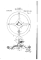
- Figure 1 is a plan view showing the top of the member secured to the steering column and the wheel thrown back therefrom, part of the former member being broken away to show the locking bolt.
- Figure 2 is a central sectional view showing the wheel in the closed position,the section being through the line 1 1 of the steering column member illustrated in Figure 1.
- the disc 1 consists of a discshaped member 1 formed with a central boss 2 which is keyed on to the steering column.
- the disc 1 is formed with an arm 3 extendingV radially from its periphery and preferably bent downwardly at the outer end and bifurcated forming a jaw 4.
- rIhe steering wheel 5 is of extremely simple form having a solid disc portion 6 formed with integral radiating arms 7 to which the rim 8 is secured.
- the centre of the disc 6 is formed with a concaved portion 9 which extends over the boss of the disc 1 and the fastening nut of the steering column, thus presenting a smooth unbroken surface on the top of the wheel.
- a plurality of taper pins 10 preferably three in number. These pins are adapted to enter the holes 11 in the disc 1 and when the wheel is closed down they wedge tightly thereinto, making a very rigid connection between the wheel and the steering column dios. These pins when thus seated relieve the hinge connection between the wheel and the steering column support from any of the strain of the steering operation.
- a suitable latch portion 12 which is arranged within an orifice 13 in the disc 1, the inner end yof the latch 12 entering the central hole 11 and being spring held in its inner position.
- the latch portion is provided with a thumb grip 14 in the outer end by means of which it is disengaged from the pin 15 which is provided with a transverse hole into which the latch extends.
- the bottom end of the pin 15 is suitably bevelled so that when the wheel is swung downwardly the bevelled surface will engage the latch portion, pushing it Vback as the pin enters the hole.
- a device such as described Vis extremely simple to manufacture requires very littlev Wheel centre adapt-ed to receive said pin and a, ⁇ spring latch vportion extending transl0 versely ih'to one side ⁇ 0f Sa'd hole ⁇ end adapted toengage s aid pin in locking Contact to hold the Wheel in locking engagement with .the post dise.
Landscapes
- Engineering & Computer Science (AREA)
- Chemical & Material Sciences (AREA)
- Combustion & Propulsion (AREA)
- Transportation (AREA)
- Mechanical Engineering (AREA)
- Steering Controls (AREA)
Description
A.A.oes. MOTOR CAR STEERING WHEEL. PFLl-CATION FILED FEB- ]0' 1920.
1,410, 159. Patented Mar. 21, 1922',
UNITED sTATEs PATENT OFFICE.v
AALBERT A. BoGGs, or TORONTO, ONTARIO, CANADA.
i MoroR-cAn-STEERING WHEEL.
To all whom it may concern:
Be it known that I, ALBERT A. Bones, a citizen of the United States of America, and resident of the city of Toronto, county of York, Province of Ontario, in the Dominion of Canada, have invented certain new and useful Improvements in Motor- Car-Steering Wheels, described in the following specification and illustrated in the accompanying drawings, that form part of the same.
The principal objects of this invention are, to enable the driver of a motor car getting into and out of his seat with the least amount of difficulty and inconvenience through the proximity of the steering wheel, and to devise a form of steering wheel connection, which is extremely simple in construction and is very rigid when locked but which may be moved entirely out of the way of the driver when getting into and out of his seat with a very simple operation.
The principal feature vof the invention consists in the `novel construction and arrangement of parts, whereby the steering wheel is pivotally mounted upon a member secured to the steering column and is rigidly locked in the closed position by a plurality of rigid stud members in one of the members entering corresponding openings in the adjacent member.
In the drawings, Figure 1 is a plan view showing the top of the member secured to the steering column and the wheel thrown back therefrom, part of the former member being broken away to show the locking bolt.
Figure 2 is a central sectional view showing the wheel in the closed position,the section being through the line 1 1 of the steering column member illustrated in Figure 1.
-It is well known to those skilled in the art that a very heavy strain is being continuously placed upon the steering wheel of a motor car and that the connection between the wheel and steering post must be of a rigid nature. Various forms of steering wheels have been devised which would enable them being movedso as to allow the driver greater room in getting into and out of his seat and while some of these have been adopted they have only been placed in the higher priced cars owing to their being so expensive.
According to the present invention a very simple and rigid structure is produced and specification of Lemrsratent. Patented Mar, 21, 1922;
Application led February 10,1920... Serial No. 357,604.
it consists of a discshaped member 1 formed with a central boss 2 which is keyed on to the steering column. The disc 1 is formed with an arm 3 extendingV radially from its periphery and preferably bent downwardly at the outer end and bifurcated forming a jaw 4.
The centre of the disc 6 is formed with a concaved portion 9 which extends over the boss of the disc 1 and the fastening nut of the steering column, thus presenting a smooth unbroken surface on the top of the wheel.
In the disc 6 of the wheel are rigidly secured a plurality of taper pins 10 preferably three in number. These pins are adapted to enter the holes 11 in the disc 1 and when the wheel is closed down they wedge tightly thereinto, making a very rigid connection between the wheel and the steering column dios. These pins when thus seated relieve the hinge connection between the wheel and the steering column support from any of the strain of the steering operation.
In order to lock the steering Wheel in place I provide a suitable latch portion 12 which is arranged within an orifice 13 in the disc 1, the inner end yof the latch 12 entering the central hole 11 and being spring held in its inner position. The latch portion is provided with a thumb grip 14 in the outer end by means of which it is disengaged from the pin 15 which is provided with a transverse hole into which the latch extends.
The bottom end of the pin 15 is suitably bevelled so that when the wheel is swung downwardly the bevelled surface will engage the latch portion, pushing it Vback as the pin enters the hole. v
A device such as described Vis extremely simple to manufacture requires very littlev Wheel centre adapt-ed to receive said pin and a,` spring latch vportion extending transl0 versely ih'to one side` 0f Sa'd hole `end adapted toengage s aid pin in locking Contact to hold the Wheel in locking engagement with .the post dise.
ALBERT A. BOGGS.
Priority Applications (1)
| Application Number | Priority Date | Filing Date | Title |
|---|---|---|---|
| US357604A US1410159A (en) | 1920-02-10 | 1920-02-10 | Motor-car-steering wheel |
Applications Claiming Priority (1)
| Application Number | Priority Date | Filing Date | Title |
|---|---|---|---|
| US357604A US1410159A (en) | 1920-02-10 | 1920-02-10 | Motor-car-steering wheel |
Publications (1)
| Publication Number | Publication Date |
|---|---|
| US1410159A true US1410159A (en) | 1922-03-21 |
Family
ID=23406297
Family Applications (1)
| Application Number | Title | Priority Date | Filing Date |
|---|---|---|---|
| US357604A Expired - Lifetime US1410159A (en) | 1920-02-10 | 1920-02-10 | Motor-car-steering wheel |
Country Status (1)
| Country | Link |
|---|---|
| US (1) | US1410159A (en) |
-
1920
- 1920-02-10 US US357604A patent/US1410159A/en not_active Expired - Lifetime
Similar Documents
| Publication | Publication Date | Title |
|---|---|---|
| US1286065A (en) | Device for attaching the ends of wire wheel-spokes to metal rims. | |
| US2155123A (en) | Folding steering wheel | |
| US1410159A (en) | Motor-car-steering wheel | |
| US1540470A (en) | Mud hook | |
| US2797036A (en) | Lock mechanism for a spare tire | |
| US1881567A (en) | Spare wheel and tire lock | |
| US1508547A (en) | Attachment for vehicle wheels | |
| US1918918A (en) | Foot pedal attachment | |
| US1843676A (en) | Steering wheel | |
| US438021A (en) | Movable vehicle-step | |
| US499514A (en) | James buchanan | |
| US427415A (en) | Balanced car-wheel | |
| US2042714A (en) | Vehicle wheel | |
| US526075A (en) | Sand-band | |
| US1420446A (en) | Steering wheel | |
| US1497742A (en) | Vehicle steering gear | |
| US465135A (en) | Vehicle-wheel | |
| US414782A (en) | Vehicle-wheel | |
| US1376035A (en) | Dehotthtable rim | |
| US384335A (en) | Wheel-fender for carriages | |
| US1334417A (en) | Detachable steering-wheel | |
| US300737A (en) | rowlett | |
| US1223977A (en) | Wire wheel construction. | |
| US379841A (en) | Wheel | |
| US308882A (en) | Maurice e |