US1410100A - Hydraulic apparatus - Google Patents
Hydraulic apparatus Download PDFInfo
- Publication number
- US1410100A US1410100A US415118A US41511820A US1410100A US 1410100 A US1410100 A US 1410100A US 415118 A US415118 A US 415118A US 41511820 A US41511820 A US 41511820A US 1410100 A US1410100 A US 1410100A
- Authority
- US
- United States
- Prior art keywords
- pistons
- water
- capacities
- crank
- oil
- Prior art date
- Legal status (The legal status is an assumption and is not a legal conclusion. Google has not performed a legal analysis and makes no representation as to the accuracy of the status listed.)
- Expired - Lifetime
Links
- XLYOFNOQVPJJNP-UHFFFAOYSA-N water Substances O XLYOFNOQVPJJNP-UHFFFAOYSA-N 0.000 description 30
- 230000005540 biological transmission Effects 0.000 description 8
- 239000007788 liquid Substances 0.000 description 7
- 238000005461 lubrication Methods 0.000 description 3
- 241001125879 Gobio Species 0.000 description 2
- 238000010276 construction Methods 0.000 description 2
- 239000012530 fluid Substances 0.000 description 2
- 239000011435 rock Substances 0.000 description 2
- WFAULHLDTDDABL-UHFFFAOYSA-N Proxazole citrate Chemical compound OC(=O)CC(O)(C(O)=O)CC(O)=O.C=1C=CC=CC=1C(CC)C1=NOC(CCN(CC)CC)=N1 WFAULHLDTDDABL-UHFFFAOYSA-N 0.000 description 1
- 229910000831 Steel Inorganic materials 0.000 description 1
- 230000000694 effects Effects 0.000 description 1
- 238000000034 method Methods 0.000 description 1
- 238000012856 packing Methods 0.000 description 1
- 230000037452 priming Effects 0.000 description 1
- 239000010959 steel Substances 0.000 description 1
- 230000009885 systemic effect Effects 0.000 description 1
Images


Classifications
-
- F—MECHANICAL ENGINEERING; LIGHTING; HEATING; WEAPONS; BLASTING
- F16—ENGINEERING ELEMENTS AND UNITS; GENERAL MEASURES FOR PRODUCING AND MAINTAINING EFFECTIVE FUNCTIONING OF MACHINES OR INSTALLATIONS; THERMAL INSULATION IN GENERAL
- F16H—GEARING
- F16H43/00—Other fluid gearing, e.g. with oscillating input or output
- F16H43/02—Fluid gearing actuated by pressure waves
Definitions
- This invention relates to hydraulic apparatus and has reference to wave transmission gei'ierators for use in the system of wave transmission disclosed in the specification of Letters Patent No. 9029 of 1913.
- the object ot the invention is to provide a generator which will be effective in its operation and durable in use and an important feature of the invent-ion resides in the fact that the inertia forces acting on the V.crank are balanced substantially and the forces due to pressure acting on the crank.
- T he invention consists broadly of a generator having opposed pistons operating 1n conjunction with a pair of liquid capacitiesY which are coupled together so as to be in effect a single capacity. Further features of the'invention consist of means for effecting forced ⁇ lubrication of the working parts and a special means for ensuring the maintef VpcnsatingY device which will be more specilically described hereafter, and in the case of such tools as rock drills the water pump may operate to discharge water through the drill steel as is not unusual in rock drillingapparatus.
- FIG. 1 being a sectional plan view on the line 1 1 of F ig. 2.
- Fig. 2 is a longitudinal section on the line 2 2 of Fig. 1. ⁇
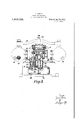
- Fig. 3 is a similar View to Fig. 2, the section being taken through the pumps and gear box, on the line 3 3 of Fig. 1, and
- Figli is a sectional elevation through the crank shaft along the line 4 4 of Fig. 2.
- the numeral 1 designates the crank shaft which has two throws' ⁇ la and 1b and connecting links 2 coiineet this crank through gudgeon pins 3 with pistons 4, each of which reciprocates in its, cylinder ⁇ 5 which is open to one or other' of the spherical capacities 6, packing leathers 7 held in position by washers 8 and a nut 9 serving to prevent leakage from the capacities.
- the crank shaft 1 is provided with a fly wheel 10, and the drive is transmitted to this fly wheel 10 through pins carried on the rotating part of the driving pulley or prime ⁇ mover engaging in recesses 11, which may be packed with ferodo.
- the two capacities 6 are coupled together'l byineans of a pipe 12 asbest shown in Fig. ⁇ 2, and the highest point of this pipe vis provided ywith a valve 13 for permitting the escape of air ywhen priming the system.
- the capacities 6V are provided with openings 14 to which pipe lines are connected by means of suitable controlling valves.
- One of the capacities 6 is connected by means of the pipe 15 and suitable f'itm'ents or unionsv 15 ⁇ and 15b with the water pump 16, -which latter serves to prime the system'V and also operates to ensure the system re'- vniaining full in spite of leakage, any leakage which may occur being made up through non-return valves within the itment or union 15 as will be readily understood by persons conversant with apparatus of this general character.
- the water pump 16 consists of a'plunger 17 which is actuated from an eccentric 18 carried upon a shaft 19, this shaft 19 being driven from the worm 20 on the end vof the crank shaft 1 by means of the Worm wheel 22.
- plunger 17 land the compensating plunger 29. It should perhaps be mentioned that a steady flou of liquid from both oil and Water pumps is ensured by providing air vessel-s 4'? the usual Way. This is desirable byreason of the fact that the pumps employed are single acting plungers ⁇ y and Without this provision the delivery would be intermittent. Assuming the system to be full of liquid the reciprocation vof the. pistons 4 acting synchronously will set up pressure waves in the system in accordance with ⁇ the now Well-known principles of transmission of power by pressure waves.
- Awave transmission ⁇ generator compris toi secure by ing a pair of pistons disposed in the same horizontal plane, a twothrovv crank located between and operatively connected to reciprecate said pistons simultaneously in oppof4 vsite directions, separate capacitiesin, relation to each of which ⁇ one of'said pistonsmovesito set up pressure Waves and; a pipey connectoni between said capacities substantially as specified.
- a Wave transmission generator comprising a pair of pistons disposed in thel same horizontal plane, a two throw crank located,
- a wave transmission generator comprising a pair of pistons disposed in the same horizontal plane, a two throw crank located between and operatively connected to reciprocate said pistons simultaneously in opposite directions, separate capacities in relation to each of which one of said pistons moves to set up pressure waves and a pipe connection between said capacities, a hollow base supporting said pistons, crank and connected capacities, an oil reservoir in said base, a water reservoir in said base, and separately operating oil and water pumps driven from a common shaft for effecting lubrication and charging the system respectively, substantially as specified.
- a wave transmission generator comprising a pair of pistons disposed in the same horizontal plane, a two throw crank located between and operatively connected to reciprocate said pistons simultaneously in opposite directions, separate capacities in relation to each of which one of said pistons moves to set up pressure waves and a pipe connection between said capacities, a hollow base supporting said pistons, crank and connected capacities, an oil reservoir in said base, a water reservoir in said base, an oil pump operating to draw oil from the oil reservoir and deliver it to the parts to be lubricated, and a water pump operating to draw water from the water reservoir and deliver it to the systen1,'substantially as specified.
- a wave transmission generator comprising a pair of pistons disposed in the same horizontal plane, a two throw crank located between and operatively7 connected to reciprocate said pistons simultaneously in opposite directions, separate capacities in relation to each of which one of said pistons moves to set up pressure waves, and a pipe connection between said capacities, a hollow base supporting said pistons, crank and connected capacities, an oil reservoir in said base, a water reservoir in said base, an oil pump operating to draw oil Jfrom the oil reservoir and deliver it to the parts to be lubricated, and a water pump operating to draw water from the water reservoir and deliver it to the system, a worm or an extension of the generator crank shaft for driving both said pumps simultaneously through wom wheel gearing, substantially as specifie 6.
- a wave transmission generator comprising a pair of pistons disposed in the same horizontal plane, a two throw crank located between and operatively connected to reciprocate said pistons simultaneonusly in opposite directions, separate capacities in relation to each of which one of said pistons moves to set up pressure waves, and a pipe connection between said capacities, a hollow base supporting said pistons, crank and connected capacities, an oil reservoir in said base, a water reservoir in said base, an oil pump operating to draw oil from the oil reservoir and deliver it to the parts to be lubricated, and a water pump operating to draw Water from the water reservoir and deliver it to the system and air vessels to which said pumps deliver and from which the oil and water respectively iow at steady pressures, substantially as specified.
Landscapes
- Engineering & Computer Science (AREA)
- General Engineering & Computer Science (AREA)
- Physics & Mathematics (AREA)
- Fluid Mechanics (AREA)
- Mechanical Engineering (AREA)
- Reciprocating Pumps (AREA)
Description
J. HANSON.
HYDRAULIC APPARATUS.
l l APPLICATION FILED OCT. 6. 1920. 1,410,100, Patented Mar. 21, 1922.
4 SHEETS-SHEET l.
1. HANSON.
nm 2 Qmw U' Tlcu A. Rm H0 DI Am CH... lllF-I L UN A0 RH DA YN Hi DI D; A
Patented Mar. 21, 1922.
4 SHEETS-SHEET 2.
J. HANSON.
HYDRAULIC APPARATUS. APPLICATION FILED QCT- 6, 1920.
1,410-, 10Q, v Patented Mar. 21, 1922.
4 SHEETS-SHEET 3- 1.HANSON.
.HYDRAULIC APPARATUS.
APPLICATION man 0016. 1920.
1 ,4 1 O, 1 O0 Patented Mar. 21, 1922.
4 SHEEIS-SHEET 4- PATENT OFFICE.
JAMES HANSON, 0F STAFFORD, ENGLAND.
HYDRAULIC APPARATUS.
Specification of Letters Patent. Patented Mal'. 21, 1922.
Application led October 6, 1920. Serial No. 415,118.
(GRANTED 'UNDER THE PROVISIONS 0F THE ,ACT OF MARCH 3, 1921, 41 STAT. I..,1313.)
To all/whom t may concern:
Be it known that I, Jarras- HiiNsoN, a subject of the King of Great Britain, and a resident of Stafford, in the county of Stafford, England, have invented certain new and useful Improvements in Hydraulic Apparatus, (for which I have liled applications in England Aug. S, 1919, Patent N o. 153,659; New Zealand on November, 6th, 1920; Mexico on December 3rd, 1920; Japan on November 13th, 1920; Brazil on November 11th, 1920; Canada on November 9th,v
1920; India on October 29th, 1920; South Africa on October 14th, 1920; Belgium on October 6th, 1920; France on October 1th, 1920;Denmark on December 29th, 1920; Holland on October 1st, 1920; Italy on October 14th, 1920; Norway on September 30th; 1920; Spain on September 30th, 1920; Sweden on October 0th, 1920; Switzerland on October 6th, 1920, and Germany on October 13th, 1920,) of which the following is a specification.
'This invention relates to hydraulic apparatus and has reference to wave transmission gei'ierators for use in the system of wave transmission disclosed in the specification of Letters Patent No. 9029 of 1913.
jThe object ot the invention is to provide a generator which will be effective in its operation and durable in use and an important feature of the invent-ion resides in the fact that the inertia forces acting on the V.crank are balanced substantially and the forces due to pressure acting on the crank.
are balanced absolutely.
T he invention consists broadly of a generator having opposed pistons operating 1n conjunction with a pair of liquid capacitiesY which are coupled together so as to be in effect a single capacity. Further features of the'invention consist of means for effecting forced `lubrication of the working parts and a special means for ensuring the maintef VpcnsatingY device which will be more specilically described hereafter, and in the case of such tools as rock drills the water pump may operate to discharge water through the drill steel as is not unusual in rock drillingapparatus.
A generator according to my invention is illustrated in the accompanying drawings, Fig. 1 being a sectional plan view on the line 1 1 of F ig. 2.
Fig. 2 is a longitudinal section on the line 2 2 of Fig. 1.`
Fig. 3 is a similar View to Fig. 2, the section being taken through the pumps and gear box, on the line 3 3 of Fig. 1, and
' Figli is a sectional elevation through the crank shaft along the line 4 4 of Fig. 2.
Referring to these drawings the numeral 1 designates the crank shaft which has two throws'` la and 1b and connecting links 2 coiineet this crank through gudgeon pins 3 with pistons 4, each of which reciprocates in its, cylinder `5 which is open to one or other' of the spherical capacities 6, packing leathers 7 held in position by washers 8 and a nut 9 serving to prevent leakage from the capacities. The crank shaft 1 is provided with a fly wheel 10, and the drive is transmitted to this fly wheel 10 through pins carried on the rotating part of the driving pulley or prime` mover engaging in recesses 11, which may be packed with ferodo.
The two capacities 6 are coupled together'l byineans of a pipe 12 asbest shown in Fig.` 2, and the highest point of this pipe vis provided ywith a valve 13 for permitting the escape of air ywhen priming the system. The capacities 6V are provided with openings 14 to which pipe lines are connected by means of suitable controlling valves.
One of the capacities 6 is connected by means of the pipe 15 and suitable f'itm'ents or unionsv 15` and 15b with the water pump 16, -which latter serves to prime the system'V and also operates to ensure the system re'- vniaining full in spite of leakage, any leakage which may occur being made up through non-return valves within the itment or union 15 as will be readily understood by persons conversant with apparatus of this general character. The water pump 16 consists of a'plunger 17 which is actuated from an eccentric 18 carried upon a shaft 19, this shaft 19 being driven from the worm 20 on the end vof the crank shaft 1 by means of the Worm wheel 22. The connection ofthe similar construction except that the water' pump is provided `with a, compensatingl plunger or unloading` device 29. This compensating plunger is so loaded by the sprinl 3,0 that, until the system is full the liquid pumped by the plunger 17 passes through the nOu-return. valve within the tment ory union 15a into the system, but immediately the systemic; full the liquid pumped by this plunger 17 simply operates to move the plunger 2.9 so, that the liquid merely oscillates in the passage 32,110, fresh liquid' beingr drawn into the pump cylinders. The Water supplyv for the Water pump is contained in" a tank 33 and the oil sup ly for the o il. pump is similarly `containe 'in a tank 34, these tanks being formed in the base of the machine.` The oil delivered at each stroke by theI plunger 26 is conducted" by wayofthe ftment or union26a and pipe B5, 35 to elect, forced lubrication of various parts of the apparatus. The method adopted will beclear upon reference to` Fig. 1, the
oil supply passing along `the 'pipes 36; and
passages 3f( to the crank shaft bearings 38 and thenceby Way of the passages: 39 and 4()I bored in the crank shaft to the passage 41 leading to the gudgeon pins 3.` An)r liquid` collecting in thecrank case and tending to escape to the outside will collect in therotating cateher 42 and will bel returned by centrifugal torce to the. crank.` case, y the periphery of the catcher 42 bei-ng provided with holes 43` to permit; this.
lThe operationlfof the vapparatus will bei best understood; from Fig. 4. In theexample shown the drive` is. effected by belts through fast; and loose pulleys, the loosey pulleyfbeingshotvn alg-144 and the fast` pulley at, 45, whileY 46 indicateslthe belt shifting;` rod. Assuming. the apparatus to be. drieen, thea crank shaft 1 will rotate continu' ously thus reciprocating the pistons 4 and also drivingthe water and oil pumps.` At
starting the water pump discharges water thereafter the Water oscillates between the.
plunger 17 land the compensating plunger 29. It should perhaps be mentioned that a steady flou of liquid from both oil and Water pumps is ensured by providing air vessel-s 4'? the usual Way. This is desirable byreason of the fact that the pumps employed are single acting plungers`y and Without this provision the delivery would be intermittent. Assuming the system to be full of liquid the reciprocation vof the. pistons 4 acting synchronously will set up pressure waves in the system in accordance with` the now Well-known principles of transmission of power by pressure waves. ,It will beA appreciated that by reason of the foregoing construction the forces due to pressure are completely balanced and the crank shaft is not subject to strains consequent upon the rapid pressure rises,V moreover the inertia 'forces are also balanced except for the slight couple due to the offset@ ting of the throws ofthe cranlr.V Of course 'I recognize that complete balance of these,
inertia forces could also be attained by adopting a complicated crank and forked connecting rods which would get rid of; the
couple, but We have found that the out oi? balance component is so small as to be quiteunimportant in practice and any advantage It, shouldifbe noted that-the term Water pump has been used for convenience in distinguishing between the pump used for f :harging the system With itsvvorkingyfluid, and the yoil pump used for lubrication purposes, butit will be understood that Where. oil is used as the Working fluid what is. characterized as the Water` pump will not be truly a Water pump, the term Water pum meaning the pumpoperating upon the Worlling fluid of the system.
, What I claim and desire Letters-Patent is 1. Awave transmission` generator compris toi secure by ing a pair of pistons disposed in the same horizontal plane, a twothrovv crank located between and operatively connected to reciprecate said pistons simultaneously in oppof4 vsite directions, separate capacitiesin, relation to each of which` one of'said pistonsmovesito set up pressure Waves and; a pipey connectoni between said capacities substantially as specified.
2. A Wave transmission generator compris ing a pair of pistons disposed in thel same horizontal plane, a two throw crank located,
between and operatively conneotedto recipV`-V rocate said pistons simultaneously in oppo site directions, separate capaci-ties in relation to each of which one of said pistons;.moves` to set up; pressure Waves, and a, pipe: connectlon between said capacities, an air diss charge valve in said pipe connection?, and
means for opening and closing said valve, substantially as specified.
3. A wave transmission generator comprising a pair of pistons disposed in the same horizontal plane, a two throw crank located between and operatively connected to reciprocate said pistons simultaneously in opposite directions, separate capacities in relation to each of which one of said pistons moves to set up pressure waves and a pipe connection between said capacities, a hollow base supporting said pistons, crank and connected capacities, an oil reservoir in said base, a water reservoir in said base, and separately operating oil and water pumps driven from a common shaft for effecting lubrication and charging the system respectively, substantially as specified.
4. A wave transmission generator comprising a pair of pistons disposed in the same horizontal plane, a two throw crank located between and operatively connected to reciprocate said pistons simultaneously in opposite directions, separate capacities in relation to each of which one of said pistons moves to set up pressure waves and a pipe connection between said capacities, a hollow base supporting said pistons, crank and connected capacities, an oil reservoir in said base, a water reservoir in said base, an oil pump operating to draw oil from the oil reservoir and deliver it to the parts to be lubricated, and a water pump operating to draw water from the water reservoir and deliver it to the systen1,'substantially as specified.
5. A wave transmission generator comprising a pair of pistons disposed in the same horizontal plane, a two throw crank located between and operatively7 connected to reciprocate said pistons simultaneously in opposite directions, separate capacities in relation to each of which one of said pistons moves to set up pressure waves, and a pipe connection between said capacities, a hollow base supporting said pistons, crank and connected capacities, an oil reservoir in said base, a water reservoir in said base, an oil pump operating to draw oil Jfrom the oil reservoir and deliver it to the parts to be lubricated, and a water pump operating to draw water from the water reservoir and deliver it to the system, a worm or an extension of the generator crank shaft for driving both said pumps simultaneously through wom wheel gearing, substantially as specifie 6. A wave transmission generator comprising a pair of pistons disposed in the same horizontal plane, a two throw crank located between and operatively connected to reciprocate said pistons simultaneonusly in opposite directions, separate capacities in relation to each of which one of said pistons moves to set up pressure waves, and a pipe connection between said capacities, a hollow base supporting said pistons, crank and connected capacities, an oil reservoir in said base, a water reservoir in said base, an oil pump operating to draw oil from the oil reservoir and deliver it to the parts to be lubricated, and a water pump operating to draw Water from the water reservoir and deliver it to the system and air vessels to which said pumps deliver and from which the oil and water respectively iow at steady pressures, substantially as specified.
In witness whereof I afiix my signature.
JAMES HANSON.
Priority Applications (1)
| Application Number | Priority Date | Filing Date | Title |
|---|---|---|---|
| US415118A US1410100A (en) | 1920-10-06 | 1920-10-06 | Hydraulic apparatus |
Applications Claiming Priority (1)
| Application Number | Priority Date | Filing Date | Title |
|---|---|---|---|
| US415118A US1410100A (en) | 1920-10-06 | 1920-10-06 | Hydraulic apparatus |
Publications (1)
| Publication Number | Publication Date |
|---|---|
| US1410100A true US1410100A (en) | 1922-03-21 |
Family
ID=23644443
Family Applications (1)
| Application Number | Title | Priority Date | Filing Date |
|---|---|---|---|
| US415118A Expired - Lifetime US1410100A (en) | 1920-10-06 | 1920-10-06 | Hydraulic apparatus |
Country Status (1)
| Country | Link |
|---|---|
| US (1) | US1410100A (en) |
Cited By (1)
| Publication number | Priority date | Publication date | Assignee | Title |
|---|---|---|---|---|
| US2429390A (en) * | 1942-12-10 | 1947-10-21 | John Waldron Corp | Hydraulic oscillator |
-
1920
- 1920-10-06 US US415118A patent/US1410100A/en not_active Expired - Lifetime
Cited By (1)
| Publication number | Priority date | Publication date | Assignee | Title |
|---|---|---|---|---|
| US2429390A (en) * | 1942-12-10 | 1947-10-21 | John Waldron Corp | Hydraulic oscillator |
Similar Documents
| Publication | Publication Date | Title |
|---|---|---|
| US2124914A (en) | Rotating bowl pump | |
| US1910876A (en) | Rotary pump | |
| US1410100A (en) | Hydraulic apparatus | |
| US1330458A (en) | Refrigerator-machine | |
| US2131910A (en) | Hydraulic transmission | |
| NO781665L (en) | PRESSURE FLUID GENERATOR. | |
| US1261061A (en) | Pump mechanism. | |
| US2136986A (en) | Hydraulic transmission for converting rotary into reciprocating motion | |
| US1652026A (en) | Pumping plant for high-pressure steam generators | |
| US566895A (en) | Single-acting crank-pump | |
| US2233227A (en) | Hydropneumatic counterbalance | |
| US1114108A (en) | Method and apparatus for pumping liquids. | |
| US378847A (en) | Mechanical movement | |
| US1697253A (en) | Transmission gear | |
| US1555598A (en) | Pump | |
| US1867470A (en) | Compressor | |
| US2816515A (en) | Pumps | |
| US251593A (en) | Means for transmitting power from steam-engines or other motors | |
| US1840867A (en) | Hydraulic power transmission | |
| US2350815A (en) | Gas compressing plant | |
| US1646294A (en) | Compression pump | |
| US2950704A (en) | Pump jacks and the like | |
| US1432673A (en) | Synchronous alternating liquid current motor | |
| US1375160A (en) | Air-pump | |
| US595175A (en) | Machinery |