US1394143A - X-ray apparatus - Google Patents
X-ray apparatus Download PDFInfo
- Publication number
- US1394143A US1394143A US333065A US33306519A US1394143A US 1394143 A US1394143 A US 1394143A US 333065 A US333065 A US 333065A US 33306519 A US33306519 A US 33306519A US 1394143 A US1394143 A US 1394143A
- Authority
- US
- United States
- Prior art keywords
- oil
- tank
- transformer
- tube
- ray
- Prior art date
- Legal status (The legal status is an assumption and is not a legal conclusion. Google has not performed a legal analysis and makes no representation as to the accuracy of the status listed.)
- Expired - Lifetime
Links
Images
Classifications
-
- H—ELECTRICITY
- H05—ELECTRIC TECHNIQUES NOT OTHERWISE PROVIDED FOR
- H05G—X-RAY TECHNIQUE
- H05G1/00—X-ray apparatus involving X-ray tubes; Circuits therefor
- H05G1/08—Electrical details
- H05G1/26—Measuring, controlling or protecting
- H05G1/54—Protecting or lifetime prediction
-
- H—ELECTRICITY
- H05—ELECTRIC TECHNIQUES NOT OTHERWISE PROVIDED FOR
- H05G—X-RAY TECHNIQUE
- H05G1/00—X-ray apparatus involving X-ray tubes; Circuits therefor
- H05G1/02—Constructional details
- H05G1/04—Mounting the X-ray tube within a closed housing
-
- H—ELECTRICITY
- H05—ELECTRIC TECHNIQUES NOT OTHERWISE PROVIDED FOR
- H05G—X-RAY TECHNIQUE
- H05G1/00—X-ray apparatus involving X-ray tubes; Circuits therefor
- H05G1/02—Constructional details
- H05G1/04—Mounting the X-ray tube within a closed housing
- H05G1/06—X-ray tube and at least part of the power supply apparatus being mounted within the same housing
Definitions
- the present invention relates to 011 1111- mersed X-ray devices and its 0b]ect Is to provide a device which may be operated in various positions while at the same time maintaining the inclosing tank completely filled with oil.
- the main tank is completely filled with oil and provision is made whereby the oil may expand and contract at' diiferent operating temperatures while malntaimng the tank substantially full at all times.
- the object of maintaining the tank filled with oil at all times is to permit the device to be tilted in any position without reducing the thickness of the layer of oil insulation about the high tension conductors or exposing these conductors to air in the tank by a displacement of the oil.
- a receptacle is provided within the main tank containing both oil and air, or other gas, and connected by means of a tube with the main body of oil, the tube being so arranged as to prevent escape of the gas into the main chamber, but to enable oil to flow to and from the main chamber into the expansion chamber in accordance with temperature changes of the apparatus.
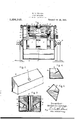
- FIG. 1 IS an eleyation of the complete apparatus with the side wall removed;
- Figs. 2, 1 and 5 are views of the expansion chamber, and
- the apparatus con sists of a transformer 6 having secondary coils 7 and 8 to the terminals 9 and 10 of which is connected an X-ray tube 11.
- the transformer and X-ray tube are placed, within a tank 12 filled with a body of oiI 13'.
- the tank may be adjustably mounted in any desired manner either on a universal suspension or arranged to be tilted about a slngle axls, as conventionally indicated by the trunnion 14.
- expansion chambers 16 and 17 On each side of the transformer core 15, as best shown in Fig. 3, are located expansion chambers 16 and 17 each contaming a quantity of oil 18 connected with the main body of oil by fine bore tubes insulating supports 26, 27; the portion .of
- the cover through which the useful stream of X-rays emerges is preferably dished, as indicated at 28, in order to decrease the thickness of the oil layer through which the -rays penetrate.
- Suitable electrical connections to the primary of the transformer and to a measuring instrument connected between the two sections of the secondary are indicated at 29, but have not been continued in full as they do not relate to the present invention.
- the heating current of the cathode may be derived from the transformer in series with a rheostat 30, as indicated in Fig. 1.
- the specific cathode circuit connections have not been illustrated for the sake of simplicity. They form no part of my present invention.
- An X-ray apparatus comprising the combination of an inclosed tank, a transformer therein, current supply conductors therefor sealed into said. tank, an X-ray tube connected to the secondary windin of said transformer, a body of oil substantially filling saidtank, and means within said tank for permitting said body of oil to change volume at different temperatures in any position of said tank While maintaining said. tank substantially filled with oil.
- An apparatus comprising the combination of an inclosed tank, a device therein evolving heat durin operation, a body of oil substantially filling said tank, a receptacle in said tank containing both oil and a gas and a tube, connecting the body of oil within said receptacle with the main body of oil in said tank, said tube ending substa-ntia-lly at the center of said receptacle, the oil in said receptacle more than half filling the same thereby preventing access of gas to the end of said tube in any position of the device.
- An electrical apparatus comprising the combination of an inclosed tank, a mounting therefor permitting said tank to betilt ed in various positions, a translating device evolving heat located therein, a bod of oil substantially filling said tank, an a re ceptacle in said tank containing both oil and a gas having an opening connecting the main body of 011 in said tank with the oil in said receptacle, said opening being arranged to be sealed against passage of gas in any position of said apparatus.
Description
W. D. COOLIDGE.
X-RAY APPARATUS.
APPLICATION FILED OCT. 24, 1919.
1,394,143. Patented Oct. 18, 1921.
Fig. l
25 23 a a 22 2/ A? 27 Ihventor: William DCQ IidQe,
His Attorney.
/ IIIII'IIIIIIIIIIIJIIIII I n UNITED STATES PATENT OFFICE.
WILLIAM D. COOLIDGE, OF SCHENEGTADY, NEW YORK, ASSIGNOR TO GENERAL ELEC- TRIO COMPANY, A CORPORATION OF NEW YORK.
X-RAY 'APPARATUS.
Specification of Letters Patent.
Patented Oct. 18, 1921.
To all whom it may concern:
Be it known that I, WILLIAM D. CooLmoE, a citizen of the United States, residing at Schenectady, in the county of Schenectady, State of New York, have invented certaln new and useful Improvements in X- Ray Apparatus, of which the following 1s a specification.
The present invention relates to 011 1111- mersed X-ray devices and its 0b]ect Is to provide a device which may be operated in various positions while at the same time maintaining the inclosing tank completely filled with oil.
In the device comprising my present 1nvention the main tank is completely filled with oil and provision is made whereby the oil may expand and contract at' diiferent operating temperatures while malntaimng the tank substantially full at all times. The object of maintaining the tank filled with oil at all times is to permit the device to be tilted in any position without reducing the thickness of the layer of oil insulation about the high tension conductors or exposing these conductors to air in the tank by a displacement of the oil.
In the specific embodiment of my invention described herein a receptacle is provided within the main tank containing both oil and air, or other gas, and connected by means of a tube with the main body of oil, the tube being so arranged as to prevent escape of the gas into the main chamber, but to enable oil to flow to and from the main chamber into the expansion chamber in accordance with temperature changes of the apparatus.
My invention will be more speclfically described in connection with the accompanying drawings in which Figure 1 IS an eleyation of the complete apparatus with the side wall removed; Figs. 2, 1 and 5, are views of the expansion chamber, and Fig. 3 1s a fragmental sectional View taken at right angles to Fig. 1, and showing the arrangement of the expansion chambers within the ap aratus.
s shown in Fig. 1, the apparatus con sists of a transformer 6 having secondary coils 7 and 8 to the terminals 9 and 10 of which is connected an X-ray tube 11. The transformer and X-ray tube are placed, within a tank 12 filled with a body of oiI 13'. The tank may be adjustably mounted in any desired manner either on a universal suspension or arranged to be tilted about a slngle axls, as conventionally indicated by the trunnion 14. On each side of the transformer core 15, as best shown in Fig. 3, are located expansion chambers 16 and 17 each contaming a quantity of oil 18 connected with the main body of oil by fine bore tubes insulating supports 26, 27; the portion .of
the cover through which the useful stream of X-rays emerges is preferably dished, as indicated at 28, in order to decrease the thickness of the oil layer through which the -rays penetrate. Suitable electrical connections to the primary of the transformer and to a measuring instrument connected between the two sections of the secondary are indicated at 29, but have not been continued in full as they do not relate to the present invention. The heating current of the cathode may be derived from the transformer in series with a rheostat 30, as indicated in Fig. 1. The specific cathode circuit connections have not been illustrated for the sake of simplicity. They form no part of my present invention.
In the operation of the described device all of the heat generated in the transformer and in the X-ray tube is imparted to the oil causing an expansion of the oil. Therefore a flow of oil occurs into the expansion chambers from the main body of oil surrounding the tube and transformer through the tubes 19 and 20 which have an opening at approximately the center of the'expansion chambers, thereb compressing the air in these chambers. Wlien the main body of oil cools and contracts an oil flow occurs in the reverse direction from the expansion chamber into the main tank. As will be clear from reference to Figs. 4 and 5, the ends of the tubes 19 and 20 are always sealed by oil in any position and there ore prevent an escape of air from the expansion chamber into the main chamber.
What I claim as new and desire to secure by Letters Patent of the United States, is:
1. An X-ray apparatus comprising the combination of an inclosed tank, a transformer therein, current supply conductors therefor sealed into said. tank, an X-ray tube connected to the secondary windin of said transformer, a body of oil substantially filling saidtank, and means within said tank for permitting said body of oil to change volume at different temperatures in any position of said tank While maintaining said. tank substantially filled with oil.
2. An apparatus comprising the combination of an inclosed tank, a device therein evolving heat durin operation, a body of oil substantially filling said tank, a receptacle in said tank containing both oil and a gas and a tube, connecting the body of oil within said receptacle with the main body of oil in said tank, said tube ending substa-ntia-lly at the center of said receptacle, the oil in said receptacle more than half filling the same thereby preventing access of gas to the end of said tube in any position of the device.
3. An electrical apparatus comprising the combination of an inclosed tank, a mounting therefor permitting said tank to betilt ed in various positions, a translating device evolving heat located therein, a bod of oil substantially filling said tank, an a re ceptacle in said tank containing both oil and a gas having an opening connecting the main body of 011 in said tank with the oil in said receptacle, said opening being arranged to be sealed against passage of gas in any position of said apparatus.
In witness whereof, I have hereunto set my hand this 17th day of October, 1919.
WILLIAM D. COOLIDGE.
Priority Applications (1)
| Application Number | Priority Date | Filing Date | Title |
|---|---|---|---|
| US333065A US1394143A (en) | 1919-10-24 | 1919-10-24 | X-ray apparatus |
Applications Claiming Priority (2)
| Application Number | Priority Date | Filing Date | Title |
|---|---|---|---|
| US333065A US1394143A (en) | 1919-10-24 | 1919-10-24 | X-ray apparatus |
| US333092A US1394144A (en) | 1919-10-24 | 1919-10-24 | Incandescent-cathode apparatus |
Publications (1)
| Publication Number | Publication Date |
|---|---|
| US1394143A true US1394143A (en) | 1921-10-18 |
Family
ID=23301228
Family Applications (2)
| Application Number | Title | Priority Date | Filing Date |
|---|---|---|---|
| US333092A Expired - Lifetime US1394144A (en) | 1919-10-24 | 1919-10-24 | Incandescent-cathode apparatus |
| US333065A Expired - Lifetime US1394143A (en) | 1919-10-24 | 1919-10-24 | X-ray apparatus |
Family Applications Before (1)
| Application Number | Title | Priority Date | Filing Date |
|---|---|---|---|
| US333092A Expired - Lifetime US1394144A (en) | 1919-10-24 | 1919-10-24 | Incandescent-cathode apparatus |
Country Status (3)
| Country | Link |
|---|---|
| US (2) | US1394144A (en) |
| FR (4) | FR519671A (en) |
| GB (1) | GB160019A (en) |
Cited By (4)
| Publication number | Priority date | Publication date | Assignee | Title |
|---|---|---|---|---|
| US2444351A (en) * | 1943-05-28 | 1948-06-29 | Rca Corp | Float type expansion chamber for closed fluid systems |
| US3145357A (en) * | 1961-07-10 | 1964-08-18 | Gen Electric | Expansion chamber for orienting liquid level |
| US3242250A (en) * | 1963-02-11 | 1966-03-22 | Wehr Steel Company | Expansion chamber for liquid cooled electrical apparatus |
| US3470307A (en) * | 1966-08-26 | 1969-09-30 | Int Standard Electric Corp | Capacitors |
Families Citing this family (4)
| Publication number | Priority date | Publication date | Assignee | Title |
|---|---|---|---|---|
| DE767887C (en) * | 1937-03-06 | 1954-08-02 | Alphonse Ferdinand Pieper | Roentgengeraet with a swiveling housing which encloses the Roentgenroehre and the transformer assigned to it |
| US2471011A (en) * | 1946-12-19 | 1949-05-24 | Arthur L Shapiro | Battery charger and rectifier therefor |
| FR2059946A1 (en) * | 1969-06-05 | 1971-06-11 | Alsthom Savoisienne | |
| US7376218B2 (en) * | 2006-08-16 | 2008-05-20 | Endicott Interconnect Technologies, Inc. | X-ray source assembly |
-
1919
- 1919-10-24 US US333092A patent/US1394144A/en not_active Expired - Lifetime
- 1919-10-24 US US333065A patent/US1394143A/en not_active Expired - Lifetime
- 1919-12-23 GB GB32194/??A patent/GB160019A/en not_active Expired
-
1920
- 1920-03-12 FR FR519671A patent/FR519671A/en not_active Expired
- 1920-03-16 FR FR22873A patent/FR22873E/en not_active Expired
-
1923
- 1923-01-17 FR FR28030D patent/FR28030E/en not_active Expired
-
1924
- 1924-10-10 FR FR30453D patent/FR30453E/en not_active Expired
Cited By (4)
| Publication number | Priority date | Publication date | Assignee | Title |
|---|---|---|---|---|
| US2444351A (en) * | 1943-05-28 | 1948-06-29 | Rca Corp | Float type expansion chamber for closed fluid systems |
| US3145357A (en) * | 1961-07-10 | 1964-08-18 | Gen Electric | Expansion chamber for orienting liquid level |
| US3242250A (en) * | 1963-02-11 | 1966-03-22 | Wehr Steel Company | Expansion chamber for liquid cooled electrical apparatus |
| US3470307A (en) * | 1966-08-26 | 1969-09-30 | Int Standard Electric Corp | Capacitors |
Also Published As
| Publication number | Publication date |
|---|---|
| FR30453E (en) | 1926-07-17 |
| US1394144A (en) | 1921-10-18 |
| GB160019A (en) | 1921-03-17 |
| FR22873E (en) | 1921-09-05 |
| FR519671A (en) | 1921-06-14 |
| FR28030E (en) | 1924-11-11 |
Similar Documents
| Publication | Publication Date | Title |
|---|---|---|
| US1394143A (en) | X-ray apparatus | |
| US2121630A (en) | X-ray apparatus | |
| US5060253A (en) | High-voltage block for an X-ray tube, the block including a cooling tank integrated with its secondary circuit | |
| US3091722A (en) | Electronic assembly packaging | |
| US2168780A (en) | X-ray tube | |
| US1992335A (en) | Shock-proof X-ray tube unit | |
| US1460815A (en) | Electric heater | |
| US2132174A (en) | X-ray apparatus | |
| US1487353A (en) | Electron-discharge apparatus | |
| US1973415A (en) | Safety system for small x-ray units | |
| US1957436A (en) | X-ray apparatus | |
| US428648A (en) | Casing for induction-coils | |
| US1671461A (en) | Electric vacuum furnace | |
| US1705721A (en) | Expansion device | |
| US3123784A (en) | High-voltage instrument transformers | |
| US1911350A (en) | Indicating device | |
| US1941978A (en) | Shockproof x-ray unit | |
| US1717216A (en) | Temperature indicator | |
| US1283286A (en) | Process of reducing metallic oxids. | |
| US785535A (en) | Electric furnace. | |
| US1968051A (en) | Shockproof x-ray apparatus | |
| US1426861A (en) | Arthur haddock | |
| US2098900A (en) | X-ray apparatus | |
| US1818785A (en) | Temperature indicator for electrical apparatus | |
| US1485352A (en) | Electric discharge apparatus |