US1386355A - Intermittent-motion device - Google Patents
Intermittent-motion device Download PDFInfo
- Publication number
- US1386355A US1386355A US394335A US39433520A US1386355A US 1386355 A US1386355 A US 1386355A US 394335 A US394335 A US 394335A US 39433520 A US39433520 A US 39433520A US 1386355 A US1386355 A US 1386355A
- Authority
- US
- United States
- Prior art keywords
- intermittent
- fly wheel
- slot
- motion device
- cam
- Prior art date
- Legal status (The legal status is an assumption and is not a legal conclusion. Google has not performed a legal analysis and makes no representation as to the accuracy of the status listed.)
- Expired - Lifetime
Links
- 238000010276 construction Methods 0.000 description 2
Images

Classifications
-
- G—PHYSICS
- G03—PHOTOGRAPHY; CINEMATOGRAPHY; ANALOGOUS TECHNIQUES USING WAVES OTHER THAN OPTICAL WAVES; ELECTROGRAPHY; HOLOGRAPHY
- G03B—APPARATUS OR ARRANGEMENTS FOR TAKING PHOTOGRAPHS OR FOR PROJECTING OR VIEWING THEM; APPARATUS OR ARRANGEMENTS EMPLOYING ANALOGOUS TECHNIQUES USING WAVES OTHER THAN OPTICAL WAVES; ACCESSORIES THEREFOR
- G03B1/00—Film strip handling
- G03B1/18—Moving film strip by means which act on the film between the ends thereof
- G03B1/38—Moving film strip by means which act on the film between the ends thereof embodying Geneva motion, e.g. Maltese-cross gearing
-
- Y—GENERAL TAGGING OF NEW TECHNOLOGICAL DEVELOPMENTS; GENERAL TAGGING OF CROSS-SECTIONAL TECHNOLOGIES SPANNING OVER SEVERAL SECTIONS OF THE IPC; TECHNICAL SUBJECTS COVERED BY FORMER USPC CROSS-REFERENCE ART COLLECTIONS [XRACs] AND DIGESTS
- Y10—TECHNICAL SUBJECTS COVERED BY FORMER USPC
- Y10T—TECHNICAL SUBJECTS COVERED BY FORMER US CLASSIFICATION
- Y10T74/00—Machine element or mechanism
- Y10T74/19—Gearing
- Y10T74/1987—Rotary bodies
- Y10T74/19879—Geneva
Definitions
- the object of my invention is to provide an intermittent motion device especially of the kind adapted for use with moving picture machines.
- my invention consists in the construction, arrangement and combination of the various parts of the device, whereby the objects contemplated are attained, as hereinafter more fully set forth, pointed out in my claims, and illustrated in the companying drawings, in which:
- Figure 1 show a side elevation of portion of a moving picture machine equippet with an intermittent motion device embodying my invention.
- Fig. 2 shows a similar view taken from the opposite side of the device, with part of the casing broken away.
- Fig. 3 shows an enlarged side elevation of the fiy wheel and the cam structure thereon.
- Fig. 4 shows an enlarged end elevation of the fly wheel
- Fig. 5 shows a detail sectional view taken on the line 55 of F 2.
- the reference character 10 to indicate generally a two-part casing in which the mechanism of a moving picture projecting device is supported.
- a main power shaft 11 Extended through the walls of the casing 10 is a main power shaft 11, which may be rotated by means of a crank or from a motor, as may be desired.
- a large gear 12 which meshes with a 13 on the light breaker shaft 14.
- a fly wheel shaft 15 mounted in the walls of the casing 10 is a fly wheel shaft 15, on which is a small gear 16 in mesh with the gear 12.
- Adjustably mounted on the casing is an intermittent sprocket shaft 17, on one end Specification of Letters Patent.
- an intermittent d vice member 1% comprising a plate generally triangular in outline, but having its surfaces curved to fit smoothly against the periphery of the y wheel 20 on the shaft 15.
- a cam slot 21, s .own in outline in Fig. 3 and F 2 which slot is deeper at its center than at its ends.
- a plate 22 which projects beyond the fly wheel as shown particularly in 2 and 3, and has its outer end curved as at 23.
- the plate 22 is provided in one face with a slot 24, shown in dotted lines in Figs. 2 and 3, arranged to register with the slot 21.
- a fly wheel an intermittent sprocket shaft rotatably mounted and mounted for adjustment circumferentially of said fly wheel, an intermittent movement member having three sides shaped to conform to the periphery of the fly wheel, projecting pins at the cor ners'of said member, said flywheel having in its periphery a cam-shaped slot deepest at its central portion, and a plate mounted 'on said cam wheel, having a registering cam slot and having a curved outer edge on WhlCll sald pins are adapted to travel.
- a fly Vwheel In a device of the class described, a fly Vwheel, an intermittent sprocket shaft rotathe fly wheel, projecting pins at the corners of said member, saidfly wheel having in its jecting pins at the corners of said member, said fly wheel having 1n its periphery a cam- 5,"
- said fly wheel having a member provided with a cam slot having its deepest part at its central' portion adjacent to the center of the fly wheel, and having a curved of said slot.
Landscapes
- Physics & Mathematics (AREA)
- General Physics & Mathematics (AREA)
- Transmission Devices (AREA)
Description
M. L. PARRET. INTERMITTE'NT MOTION DEVICE.
" Patented Aug. 2, 1921.
SHEETS-SHEET I.
.By. v
. .M. L. PARRET.
INIERMITTENT MOTION DEVICE. APPLICATION FILED JULY 6.1920.
Patented Aug. 2, 1921.
2 SHEETS-SHEET 2- Witness. 12 19 Imre nfto r. [120.7 ml. fl n/ma l By. TQM-Attorney s.
PATENT OFFICE.
MILTON L. PABRET, OE llfZARSI-TALLTOW'N, IOW'A.
INTERMITTENT-MOTION DEVICE.
Application filed July 6, 1920.
T 0 all whom it may concern:
Be it known that I, MILTON L. PARRET, a citizen of the United States, and resident of Marshalltown, in the county of Marshall and State of Iowa, have invented a certain new and useful Intermittent-lilotion Device, of which the following is a specifica tion.
The object of my invention is to provide an intermittent motion device especially of the kind adapted for use with moving picture machines.
More particularly it is my object to provide an intermittent motion device of simple, durable and inexpensive constr ction, so arranged that the parts will work accurately and smoothly for imparting intermittent rotary movement to a shaft or the like.
it-h these and other objects in view, my invention consists in the construction, arrangement and combination of the various parts of the device, whereby the objects contemplated are attained, as hereinafter more fully set forth, pointed out in my claims, and illustrated in the companying drawings, in which:
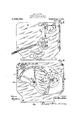
Figure 1 show a side elevation of portion of a moving picture machine equippet with an intermittent motion device embodying my invention.
Fig. 2 shows a similar view taken from the opposite side of the device, with part of the casing broken away.
Fig. 3 shows an enlarged side elevation of the fiy wheel and the cam structure thereon.
Fig. 4 shows an enlarged end elevation of the fly wheel; and
Fig. 5 shows a detail sectional view taken on the line 55 of F 2.
In the accompanying rawings 1 have used the reference character 10 to indicate generally a two-part casing in which the mechanism of a moving picture projecting device is supported. Extended through the walls of the casing 10 is a main power shaft 11, which may be rotated by means of a crank or from a motor, as may be desired.
On the shaft 11, within the casing, is a large gear 12, which meshes with a 13 on the light breaker shaft 14. Suitably mounted in the walls of the casing 10 is a fly wheel shaft 15, on which is a small gear 16 in mesh with the gear 12.
Adjustably mounted on the casing is an intermittent sprocket shaft 17, on one end Specification of Letters Patent.
Patented Aug. 2, 1921.
eel-m1 No. 394,335.
of which is the intermittent sprocket 18. @n the other end of the shaft 17 is an intermittent d vice member 1% comprising a plate generally triangular in outline, but having its surfaces curved to fit smoothly against the periphery of the y wheel 20 on the shaft 15.
1n the periphery of the fly wheel 20 and extending part way across the fly wheel, is a cam slot 21, s .own in outline in Fig. 3 and F 2, which slot is deeper at its center than at its ends. Inset in the fly wheel 20 is a plate 22, which projects beyond the fly wheel as shown particularly in 2 and 3, and has its outer end curved as at 23. The plate 22 is provided in one face with a slot 24, shown in dotted lines in Figs. 2 and 3, arranged to register with the slot 21.
ljacent to the points of the intermittent motion member 19 are laterally extending pins 25, two of which normally rest adjacent to the periphery of the fly wheel 20. As the fly wheel 20 is rotated in the direction, for instance, indicated by the arrow in 3, it will be noted that when the cam slot of the fly wheel reaches the intermittent motion device member 19, one of the pins will enter the slot 24 and tra el in the slot or notch 21.
I have found, in experimenting with a device of this kind, that where the curved outer end 23 is not provided. dithculty sometimes occurs when the pins 25 pass the deepest parts of the cam slots. Sometimes there is a tendency for the member 19 to turn in the wrong direction, and the pins are sometimes brolren of. I have, therefore, provided the present device, having the plate 22 with its curved outer edge 23. It will be seen that as the first pin travels in the cam slots, the member 19 and the shaft 17 on which it is mounted, will be rotated slightly for causing the next pin 25, and a little later the third pin 25, to travel smoothly on the curved surface 23, as illustrated, for instance, by dotted lines in Fig. 3. The engagement of the curved surface 23 with the two outer pins 25 during the continued rotation of the fly wheel carries the inner pin 25, which is received in the cam slots, past the deepest portions of said slots without any danger of stoppage or breaking the inner pin and with a smooth, accurate movement.
In the construction just described and explained, lies what I consider a very great advantage in my present intermittent motion device over anything I have known heretofore. a 7 It will, of course, be understood that the parts may be geared for securing the desired relative speeds for imparting the proper speed to the fly wheel and from thence to the intermittent sprocket 18.
In 1 I have shown my device installed a'spart of a moving picture machine, and have shown certain of the other parts of the machine in order to shown the relative position of my device. I have indicated the film by the reference character 26, and have shown the feed sprocket 27 and the take-up sprocket 28. The shutter mechanism I have indicated generally by the reference character 29. The numeral 30 indicates the handle for adjusting the support for the shaft 17. a V I claim as my invention: 7
1. In a device of the class described, a fly wheel, an intermittent sprocket shaft rotatably mounted and mounted for adjustment circumferentially of said fly wheel, an intermittent movement member having three sides shaped to conform to the periphery of the fly wheel, projecting pins at the cor ners'of said member, said flywheel having in its periphery a cam-shaped slot deepest at its central portion, and a plate mounted 'on said cam wheel, having a registering cam slot and having a curved outer edge on WhlCll sald pins are adapted to travel.
2. In a device of the class described, a fly Vwheel, an intermittent sprocket shaft rotathe fly wheel, projecting pins at the corners of said member, saidfly wheel having in its jecting pins at the corners of said member, said fly wheel having 1n its periphery a cam- 5,"
shaped slot deepest at its central portion, and a plate mounted on said cam wheel, having a registering cam slot and having a curved outer edge on which two of said pins travel while the third pin is passing the deepest part of said slot.
of the periphery of said fly wheel, and pins at the points of said intermittent movement member, said fly wheel having a member provided with a cam slot having its deepest part at its central' portion adjacent to the center of the fly wheel, and having a curved of said slot.
7 De Moines, Iowa, June 11, 1920. c
' MILTON
Priority Applications (1)
| Application Number | Priority Date | Filing Date | Title |
|---|---|---|---|
| US394335A US1386355A (en) | 1920-07-06 | 1920-07-06 | Intermittent-motion device |
Applications Claiming Priority (1)
| Application Number | Priority Date | Filing Date | Title |
|---|---|---|---|
| US394335A US1386355A (en) | 1920-07-06 | 1920-07-06 | Intermittent-motion device |
Publications (1)
| Publication Number | Publication Date |
|---|---|
| US1386355A true US1386355A (en) | 1921-08-02 |
Family
ID=23558507
Family Applications (1)
| Application Number | Title | Priority Date | Filing Date |
|---|---|---|---|
| US394335A Expired - Lifetime US1386355A (en) | 1920-07-06 | 1920-07-06 | Intermittent-motion device |
Country Status (1)
| Country | Link |
|---|---|
| US (1) | US1386355A (en) |
-
1920
- 1920-07-06 US US394335A patent/US1386355A/en not_active Expired - Lifetime
Similar Documents
| Publication | Publication Date | Title |
|---|---|---|
| US1691408A (en) | Timing device | |
| US1386355A (en) | Intermittent-motion device | |
| US3076351A (en) | Indexing mechanism | |
| US1641392A (en) | Mechanical movement and windshield-cleaning apparatus involving the same | |
| US1920969A (en) | Mechanical movement | |
| US2048194A (en) | Intermittent movement | |
| US1825442A (en) | Driving device employing maltese cross wheels | |
| US1152989A (en) | Motion-picture device. | |
| US2533317A (en) | Tape control device | |
| US1561060A (en) | Motion-picture apparatus | |
| US1893189A (en) | Motion picture machine | |
| US1159791A (en) | Motion-picture projector. | |
| US1039501A (en) | Moving-picture camera and projection-machine. | |
| US955840A (en) | Mechanism for the feeding of kinematograph-films. | |
| US1292242A (en) | Sprocket. | |
| US2607236A (en) | Geneva gearing | |
| US1304854A (en) | Mechanical movement for motion-picture machines | |
| US1534326A (en) | Moving-picture projector | |
| US1680295A (en) | Motion-picture apparatus | |
| US2968966A (en) | Intermittent motion device for projectors | |
| USRE17626E (en) | A corpora | |
| US1194113A (en) | Power-transmission mechanism | |
| GB1328593A (en) | Motion picture camera mechanisms | |
| US1129754A (en) | Moving-picture machine. | |
| US1702302A (en) | Device for stopping cinematographic projection apparatus |