US1376216A - Three-piece metallic shipping-barbel - Google Patents
Three-piece metallic shipping-barbel Download PDFInfo
- Publication number
- US1376216A US1376216A US1376216DA US1376216A US 1376216 A US1376216 A US 1376216A US 1376216D A US1376216D A US 1376216DA US 1376216 A US1376216 A US 1376216A
- Authority
- US
- United States
- Prior art keywords
- flanges
- barrel
- section
- sections
- shipping
- Prior art date
- Legal status (The legal status is an assumption and is not a legal conclusion. Google has not performed a legal analysis and makes no representation as to the accuracy of the status listed.)
- Expired - Lifetime
Links
- 238000012856 packing Methods 0.000 description 22
- 238000003197 gene knockdown Methods 0.000 description 9
- 238000010276 construction Methods 0.000 description 5
- 239000007788 liquid Substances 0.000 description 4
- 238000005096 rolling process Methods 0.000 description 4
- 239000000463 material Substances 0.000 description 2
- 239000002184 metal Substances 0.000 description 2
- 240000007817 Olea europaea Species 0.000 description 1
- 208000027418 Wounds and injury Diseases 0.000 description 1
- 230000006835 compression Effects 0.000 description 1
- 238000007906 compression Methods 0.000 description 1
- 230000006378 damage Effects 0.000 description 1
- 235000013305 food Nutrition 0.000 description 1
- 208000014674 injury Diseases 0.000 description 1
- 238000004519 manufacturing process Methods 0.000 description 1
- 239000003921 oil Substances 0.000 description 1
- 230000002093 peripheral effect Effects 0.000 description 1
- 239000000341 volatile oil Substances 0.000 description 1
- XLYOFNOQVPJJNP-UHFFFAOYSA-N water Substances O XLYOFNOQVPJJNP-UHFFFAOYSA-N 0.000 description 1
Images

Classifications
-
- B—PERFORMING OPERATIONS; TRANSPORTING
- B65—CONVEYING; PACKING; STORING; HANDLING THIN OR FILAMENTARY MATERIAL
- B65D—CONTAINERS FOR STORAGE OR TRANSPORT OF ARTICLES OR MATERIALS, e.g. BAGS, BARRELS, BOTTLES, BOXES, CANS, CARTONS, CRATES, DRUMS, JARS, TANKS, HOPPERS, FORWARDING CONTAINERS; ACCESSORIES, CLOSURES, OR FITTINGS THEREFOR; PACKAGING ELEMENTS; PACKAGES
- B65D7/00—Containers having bodies formed by interconnecting or uniting two or more rigid, or substantially rigid, components made wholly or mainly of metal
- B65D7/12—Containers having bodies formed by interconnecting or uniting two or more rigid, or substantially rigid, components made wholly or mainly of metal characterised by wall construction or by connections between walls
- B65D7/24—Containers having bodies formed by interconnecting or uniting two or more rigid, or substantially rigid, components made wholly or mainly of metal characterised by wall construction or by connections between walls collapsible, e.g. with all parts detachable
- B65D7/30—Fastening devices for holding collapsible containers in erected state, e.g. integral with container walls
-
- Y—GENERAL TAGGING OF NEW TECHNOLOGICAL DEVELOPMENTS; GENERAL TAGGING OF CROSS-SECTIONAL TECHNOLOGIES SPANNING OVER SEVERAL SECTIONS OF THE IPC; TECHNICAL SUBJECTS COVERED BY FORMER USPC CROSS-REFERENCE ART COLLECTIONS [XRACs] AND DIGESTS
- Y10—TECHNICAL SUBJECTS COVERED BY FORMER USPC
- Y10T—TECHNICAL SUBJECTS COVERED BY FORMER US CLASSIFICATION
- Y10T24/00—Buckles, buttons, clasps, etc.
- Y10T24/21—Strap tighteners
- Y10T24/2189—Circular flange container clamp
-
- Y—GENERAL TAGGING OF NEW TECHNOLOGICAL DEVELOPMENTS; GENERAL TAGGING OF CROSS-SECTIONAL TECHNOLOGIES SPANNING OVER SEVERAL SECTIONS OF THE IPC; TECHNICAL SUBJECTS COVERED BY FORMER USPC CROSS-REFERENCE ART COLLECTIONS [XRACs] AND DIGESTS
- Y10—TECHNICAL SUBJECTS COVERED BY FORMER USPC
- Y10T—TECHNICAL SUBJECTS COVERED BY FORMER US CLASSIFICATION
- Y10T292/00—Closure fasteners
- Y10T292/48—Seals
Definitions
- This invention relates to improvements in a three-piece metallic shipping barrel, so constructed that when its parts are separated, they will nest one within the other for empty return shipment, whereby the knock-down barrel occupies about one-third of the shipping space of the assembled barrel.
- the primary object of my present improvement is to provide a knock-down nestable metallic barrel, comprising a central section and two end sections, so constructed that the end sections may be closely nested one within the other and the two nested within the central section, whereby the knock-down barrel occupies approximately one-third of the shipping space of the assembled barrel.
- Another object of my invention is to provide a three-section lmock-down nestable barrel, the central section having its opposite ends provided with peripheral annular laterally extending flanges, and the end sec tions having their inner ends provided with annular laterally projecting flanges cooperating with the flanges of the central section to receive between them a packing ring, and a sectional clamping ring embracing the flanges that clamp them tightly together and compress the packing whereby a rigid liquidtight barrel is provided.
- a further object of my invention is to provide a sectional barrel havingthe center and end sections with flanges as de scribed in the immediately foregoing paragraph, and sectional rings having at their inner faces U-shaped grooves to clamp the flanges and hold the sections tightly together and at the same time act as rolling hoops for the barrel and as a protection to the flanges of the three sections.
- a further object of my improvement comprises a center and two end sections consisting in making one end section of a diameter smaller than the diameter of the central section about equal to the thickness of the material, whereby that end section may be nested within the central section, and to make the other end section of a diameter smaller than the first end section about equal to the thickness of the material whereby it can be nested within the first said end section, and both end sections closely nested within the central section.
- a further object of my invention is to so construct the clamping bands that when the three sections of the barrel are nested, the clamping bands or hoops will receive the flanges of the nested parts and also the packing, so that all the parts for the complete barrel are held in their nested positions with all the necessary parts for assembling into a rigid liquid-tight barrel.
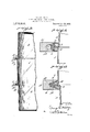
- Figure 1 is a side elevation of my improved three-section shipping barrel.
- Fig. 2 is a longitudinal section through one side of the barrel.
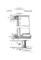
- Fig. 3 is an enlargedsection through the adjacent ends of the larger end section and central section and the clamping ring in position for drawing the parts tightly together.
- Fig. 4 is a sectional view through the adjacent ends of the central section and smaller end section showing the clamping ring drawn to clamping position and the packing compressed between the annular lateral flanges ofthe two sections.
- Fig. 5 is a longitudinal sectional view showing the three sections of the barrel, the clamping rings and the paekings in position for return shipment.
- Fig. 6 is a side elevation of the central section.
- Fig. 7 is a top plan view of two of the meeting ends of the clamping ring, showing itin position on the adjacent flanges of the central and end sections.
- Fig. 8 is a side elevation at right angles to Fig. 7.
- Metallic barrels are extensively used for shipping liquids and are recognized by the trade as the best form of barrel for that purpose. They are too expensive to discard and because of their bulkiness the return freight on them is expensive. Especially is this true where the freight is reckoned on space occupied, such as in shipping, rather than weight. Therefore, there has for a long time been a demand for a mechanically practical knock-down nestable shipping barrel which will occupy the least possible space without sacrificing the practicability of the barrel when in its assembled condition. Many efforts have been made to produce a sectional barrel which would occupy a small space when knocked. down, and which at the same time when assembled produces a practical liquid barrel adapted to receive without injury the rough knocks and treatment that such barrels receive.
- WVhile my barrel may be used for shipping all kinds of liquids, it is more particularly intended for the shipping of liquids that are used as foods, such, for instance, as the essential oils, and that are transported by water from foreign countries and returned empty, for instance in the case of: olive and similar oils, that are so largely obtained from foreign lands.
- my improved three-part knock-down barrel comprises a central portion 1, and two end portions 2 and 3. Each end of the central. portion is provided with an annular laterally extending flange which has an approximately straight part 4:, and a curved end 5, which forms a groove tor the reception of a suitable packing ring 6.
- the inner end of the end section 2 has a laterally extending flange of the same con quality of rubber.
- the other end section 3 has an annular laterally extending flange at its inner end of a similar shape in that it has a straight part 9 and a curved part 10.
- These combined hoops and clamping rings 11 are made into several sections preferably two or thrc, and their ends are united by a turn-lnickle member having at its center a nut 13, and at its opposite ends 14 and 15 right and left screw threads, so that when the tllllb buckle is revolved by a suitable wrench on the nut 13, the ends of: the combined ring a nd rolling hoop 11 will be drawn together and toward the sections of the barrel, and will flex the curved ends of the flanges toward each other, as shown in Fig. 4;, thus coinprcssing the rubber packing (5 between them, and making a liquid-tight joint.
- end section 2 is larger than the end sect-ion 3. and that the end section 2 is smaller in. diameter than the central section 1, the (lit fercnce being preferably approximately the thickness of the metal, so that when the section 2 is disassembled, it can be nested closely within the central section 1, as shown in Fig. 5.
- the end section 3 is smaller in diameter than the end section 2, the (litterence preferably being approximately the thickness of the metalso that the section 3 can be closely nested within the section 2, as shown. in Fig. 5.
- the bung '16 is placed in the central section 1, where it is protected and does not interfere with the nesting of the parts.
- a suitable seal is provided for the turn-buckle 13.
- it consists in passing a wire 18 through the angular portion of the turnbuckle, and through one section of the hoop 11, as at 19, and having the ends of the wire fastened by a suitable seal 20. This will prevent the barrel being opened without breaking the seal.
- a three-piece knock down barrel comprising a central section having laterally extending flanges at its ends, two end sections each having closed outer ends and annular laterally extending flanges at their inner open ends, all said flanges having their inner edges approximately straight and normally in engagement and their outer edges normally separated to receive a packing between them, and a clamping ring having an outwardly tapered groove in its inner side engaging the separated outer edges of the flanges for drawing them toward each other to hold the straight portions of the flanges firmly together and compress the packing between the outer separated edges of the flanges.
- a three-piece knock down barrel comprising central and end sections, each having annular laterally extending corresponding flanges at their adjacent ends to receive between them a packing, the inner edges of the flanges normally in engagement and the outer edges normally separated, said flanges capable of flexing toward each other, and a clamping ring having an annular groove in its inner side tapering outward to engage the outer separated flexing edges of the flanges for drawing them together for the purpose of firmly holding the inner edges of the flanges against each other to form a rigid structure and at the same time compress the packing between the separated outer edges of the flanges.
- a three-piece shipping barrel comprising central and end sections having their adjacent ends provided with annular laterally extending flanges, the outer edges of the flanges being normally beyond a plane drawn between the inner edges of the flanges and transverse the pieces, whereby the inner edges of the flanges are normally in contact and their outer edges separated, and a clamping ring having an outwardly tapered annular recess at its inner side, the wall of which engages the outer separated edges of the flanges for the purpose described.
- a three section barrel comprising acentral section having at each end an annular laterally extending flange, two sections having closed outer ends and laterally extending flanges at their inner ends cooperating with the flanges of the central section, means for clamping the flanges toward each other, one end section having a smaller diameter than the central section to nest therein and the other end section of smaller diameter than the first-mentioned section to nest therein, whereby a close nesting of the parts is accomplished.
- a three section barrel comprising a central section having at each end an annular laterally extending flange with their outer edges constructed to receive packings, two end sections having closed outer ends and annular laterally extending flanges at their outer ends cooperating with the flanges of the central section, the flanges on one end section being wider than the flanges of the central section, and the flanges of the other end section being wider than the flanges of the first-mentioned end section, for the purpose described.
- a three-section barrel comprising a central section having at each end an annular laterally extending flange, two end sections each having closed outer ends and annular laterally extending flanges at their innor ends, one end section being smaller in diameter than the central section to nest therein in inverted position, and the other end section having a smaller diameter than the first-mentioned end section to nest therein in inverted position, the flange of the larger end section being wider than the flanges of the central section, and the flange of the smaller end section wider than the flange of the larger end section, and all said flanges having their outer portions provided with an alined annular groove to receive a packing, and means for drawing the flanges together in assembled ositions.
Landscapes
- Engineering & Computer Science (AREA)
- Mechanical Engineering (AREA)
- Gasket Seals (AREA)
Description
G. E. MITTINGER.
THREE PIECE METALLIC SHIPPING BARREL.
APPLICATION FILED MAY 18. 1920.
Patented Apr. 26, 19.23..
3 SHEETS-SHEET 1.
G. E. MITTINGER.
THREE PIECE METALLIC SHIPPING BARREL.
APPLICATION FILED MAYIB, 1920.
Patented Apr. 26, 1921.
3 SHEETSSHEET 2.
G. E. MITTINGER.
THREE PIECE METALLIC SHIPPING BARREL.
APPLICATION FILED MAY 18, I920.
Patented Apr. 26, 1921.
3 SHEETSSHEET 3- UNITED STATES GEORGE EUGENE MITTINGER, OF YOUNGSTOWN, OHIO.
THREE-PIECE METALLIC SHIPPING-BARREL.
Specification of Letters Patent.
Patented Apr. 26, 1921.
Application filed May 18, 1920. Serial No. 382,326.
To cZZ whom it may concern:
Be it known that I, GEORGE E. MrrrINenR, a citizen of the United States, residing at Youngstown, in the county of Mahoning and State of Ohio, have invented certain new and useful Improvements in' Three-Piece Metallic Shipping-Barrels, of which the following is a specification, reference being had therein to the accompanying drawing.
This invention relates to improvements in a three-piece metallic shipping barrel, so constructed that when its parts are separated, they will nest one within the other for empty return shipment, whereby the knock-down barrel occupies about one-third of the shipping space of the assembled barrel.
The primary object of my present improvement is to provide a knock-down nestable metallic barrel, comprising a central section and two end sections, so constructed that the end sections may be closely nested one within the other and the two nested within the central section, whereby the knock-down barrel occupies approximately one-third of the shipping space of the assembled barrel.
Another object of my invention is to provide a three-section lmock-down nestable barrel, the central section having its opposite ends provided with peripheral annular laterally extending flanges, and the end sec tions having their inner ends provided with annular laterally projecting flanges cooperating with the flanges of the central section to receive between them a packing ring, and a sectional clamping ring embracing the flanges that clamp them tightly together and compress the packing whereby a rigid liquidtight barrel is provided.
A further object of my invention is to provide a sectional barrel havingthe center and end sections with flanges as de scribed in the immediately foregoing paragraph, and sectional rings having at their inner faces U-shaped grooves to clamp the flanges and hold the sections tightly together and at the same time act as rolling hoops for the barrel and as a protection to the flanges of the three sections.
A further object of my improvement comprises a center and two end sections consisting in making one end section of a diameter smaller than the diameter of the central section about equal to the thickness of the material, whereby that end section may be nested within the central section, and to make the other end section of a diameter smaller than the first end section about equal to the thickness of the material whereby it can be nested within the first said end section, and both end sections closely nested within the central section. V
A further object of my invention is to so construct the clamping bands that when the three sections of the barrel are nested, the clamping bands or hoops will receive the flanges of the nested parts and also the packing, so that all the parts for the complete barrel are held in their nested positions with all the necessary parts for assembling into a rigid liquid-tight barrel.
Further objects of my present invention will appear from the following description.
In the accompanying drawings: Figure 1 is a side elevation of my improved three-section shipping barrel.
Fig. 2 is a longitudinal section through one side of the barrel.
Fig. 3 is an enlargedsection through the adjacent ends of the larger end section and central section and the clamping ring in position for drawing the parts tightly together.
Fig. 4: is a sectional view through the adjacent ends of the central section and smaller end section showing the clamping ring drawn to clamping position and the packing compressed between the annular lateral flanges ofthe two sections.
Fig. 5 is a longitudinal sectional view showing the three sections of the barrel, the clamping rings and the paekings in position for return shipment.
Fig. 6 is a side elevation of the central section. j
Fig. 7 is a top plan view of two of the meeting ends of the clamping ring, showing itin position on the adjacent flanges of the central and end sections.
Fig. 8 is a side elevation at right angles to Fig. 7. V
Metallic barrels are extensively used for shipping liquids and are recognized by the trade as the best form of barrel for that purpose. They are too expensive to discard and because of their bulkiness the return freight on them is expensive. Especially is this true where the freight is reckoned on space occupied, such as in shipping, rather than weight. Therefore, there has for a long time been a demand for a mechanically practical knock-down nestable shipping barrel which will occupy the least possible space without sacrificing the practicability of the barrel when in its assembled condition. Many efforts have been made to produce a sectional barrel which would occupy a small space when knocked. down, and which at the same time when assembled produces a practical liquid barrel adapted to receive without injury the rough knocks and treatment that such barrels receive.
Although this demand has existed, so far as I am aware, such a sectional barrel has not heretofore been produced which would meet the conditions and requirements 01" such packages.
By my construction, which is the result of years of practical experience in the manufacture of metal barrels, I have in this three piece structure produced a sectional knockdown barrel which is of a practical construction when assembled and will stand the rough usage and meet the other necessary requirements, while at the same time when disassembled the parts can be closely nested to occupy the least possible space for a practical structure and with all its parts united when disassembled so that they are all present and ready for use when the barrel is to be assembled.
WVhile my barrel may be used for shipping all kinds of liquids, it is more particularly intended for the shipping of liquids that are used as foods, such, for instance, as the essential oils, and that are transported by water from foreign countries and returned empty, for instance in the case of: olive and similar oils, that are so largely obtained from foreign lands.
Referring now to the drawings, my improved three-part knock-down barrel comprises a central portion 1, and two end portions 2 and 3. Each end of the central. portion is provided with an annular laterally extending flange which has an approximately straight part 4:, and a curved end 5, which forms a groove tor the reception of a suitable packing ring 6.
The inner end of the end section 2 has a laterally extending flange of the same con quality of rubber. The other end section 3 has an annular laterally extending flange at its inner end of a similar shape in that it has a straight part 9 and a curved part 10.
When the center and end sections 1, 2 and 3 are in their assembled positions, the packing (3 is placed betwecn the curved ends 01" the flanges as shown in F ig. 3, and a combined clamping ring and hoop 11 has at its inner edge an elongated tapered groove 12, adapted to embrace the ends of the flanges, as shown in Fig. 3. These combined hoops and clamping rings 11 are made into several sections preferably two or thrc, and their ends are united by a turn-lnickle member having at its center a nut 13, and at its opposite ends 14 and 15 right and left screw threads, so that when the tllllb buckle is revolved by a suitable wrench on the nut 13, the ends of: the combined ring a nd rolling hoop 11 will be drawn together and toward the sections of the barrel, and will flex the curved ends of the flanges toward each other, as shown in Fig. 4;, thus coinprcssing the rubber packing (5 between them, and making a liquid-tight joint.
Attention is directed to the fact that the straight parts l, 7 and 9 of the flanges of the sections, pretci'ably substantially rest on each other, as shown in Fig. 3. before the clamping action takes place. By means of this construction when the curved ends ot the flanges are flexed toward each other to compress the packing, the straight parts 4:, 7 and 9 are held together under strong pressure so that the sections make a rigid structure by reason of the tight clamping of the straight parts of the flanges together. The grooves 12 in the combined hoops and clamping rings 11 are so shaped that the i curved ends 8 and 10 ot the flanges when flexed, as shown in Fig. 4, approximately fit the groove, thus serving further to make a rigid structure when the sections are clamped as shown in Figs. 2 and 4.
Attention is directed to the fact that the end section 2 is larger than the end sect-ion 3. and that the end section 2 is smaller in. diameter than the central section 1, the (lit fercnce being preferably approximately the thickness of the metal, so that when the section 2 is disassembled, it can be nested closely within the central section 1, as shown in Fig. 5. The end section 3 is smaller in diameter than the end section 2, the (litterence preferably being approximately the thickness of the metalso that the section 3 can be closely nested within the section 2, as shown. in Fig. 5.
To accomplish straight part of the flange 7 ot the section 2 longz cr i an the straight part .4; of the adjacent flans're on the central section. and the straight part 9 of the flange of the end section 3 is wider than the straight part 7 of this result. T ma e the the end section 2. By this arrangement the end sections can be nested within each other and both nested within the central section, while at the same time when they are assembled, the curved parts of the end sections and the central section are opposite each other to receive the rubber or other suitable packing 6 between them. Although the foregoing result is accomplished by this construction, in a full-sized barrel the difference in diameter between the end sections and the central sections will not be marked in appearance and not noticeable unless attention is directed to it.
By making the central and end sections of the varied relative diameters mentioned, I accomplish the close nesting of these parts which not only is economical in space for return shipment, but it causes the flanges to abut against each other in their nesting positions at one end, and permits the flanges of the three sections to be sutflciently close to be embraced with the packing ring by the combined clamping ring and rolling hoop 11, which serves to protect the flanges, and at the other end the second combined clamping ring and rolling hoop embraces the flange at the other end of the central section and its packing ring.
While I show the ends of the flanges of the three sections curved, I desire it to be understood that they could be angular so long as there is formed a space between the ends of the flanges to receive a packing, and when the ends are angular, the packing will be of a corresponding angular cross-section to fit in between the angular ends of the flanges.
Also in a barrel of this construction, the bung '16 is placed in the central section 1, where it is protected and does not interfere with the nesting of the parts.
While I have shown the packing ring 6 in the curved part of the flange of the section 3, when the parts are assembled as in Fig. 5. I desire it to be understood that this packing ring may be placed in the space 17, between the flange of the central section 1 and the lower wall of the inner end of the groove 12 of the hoop. In this instance, of course. the hoop will move inward and drop down in engagement with the straight part 9 of the flange of the section 3, thus increasing the space 17 from that shown in Fig. 5, with sufficient to receive the packing rin very little compression of it and wil also contract the hoop so that it will not project beyond the hoop at the other end of the nested parts, as it does in Fig. 5.
It will, of course, be understood that a three piece knock-down barrel of the type here described will take up considerably less shipping space than a two-piece barrel, and this difference will amount to a great deal where there is a large number of these barfrom being opened and tampered with after I it is assembled, a suitable seal is provided for the turn-buckle 13. In the form here shown, it consists in passing a wire 18 through the angular portion of the turnbuckle, and through one section of the hoop 11, as at 19, and having the ends of the wire fastened by a suitable seal 20. This will prevent the barrel being opened without breaking the seal.
Having thus described my invention, what I claim and desire to secure by Letters Patent is:
1. A three-piece knock down barrel, comprising a central section having laterally extending flanges at its ends, two end sections each having closed outer ends and annular laterally extending flanges at their inner open ends, all said flanges having their inner edges approximately straight and normally in engagement and their outer edges normally separated to receive a packing between them, and a clamping ring having an outwardly tapered groove in its inner side engaging the separated outer edges of the flanges for drawing them toward each other to hold the straight portions of the flanges firmly together and compress the packing between the outer separated edges of the flanges.
2. A three-piece knock down barrel, comprising central and end sections, each having annular laterally extending corresponding flanges at their adjacent ends to receive between them a packing, the inner edges of the flanges normally in engagement and the outer edges normally separated, said flanges capable of flexing toward each other, and a clamping ring having an annular groove in its inner side tapering outward to engage the outer separated flexing edges of the flanges for drawing them together for the purpose of firmly holding the inner edges of the flanges against each other to form a rigid structure and at the same time compress the packing between the separated outer edges of the flanges.
3. A three-piece shipping barrel comprising central and end sections having their adjacent ends provided with annular laterally extending flanges, the outer edges of the flanges being normally beyond a plane drawn between the inner edges of the flanges and transverse the pieces, whereby the inner edges of the flanges are normally in contact and their outer edges separated, and a clamping ring having an outwardly tapered annular recess at its inner side, the wall of which engages the outer separated edges of the flanges for the purpose described.
4. A three section barrel comprising acentral section having at each end an annular laterally extending flange, two sections having closed outer ends and laterally extending flanges at their inner ends cooperating with the flanges of the central section, means for clamping the flanges toward each other, one end section having a smaller diameter than the central section to nest therein and the other end section of smaller diameter than the first-mentioned section to nest therein, whereby a close nesting of the parts is accomplished.
5. A three section barrel, comprising a central section having at each end an annular laterally extending flange with their outer edges constructed to receive packings, two end sections having closed outer ends and annular laterally extending flanges at their outer ends cooperating with the flanges of the central section, the flanges on one end section being wider than the flanges of the central section, and the flanges of the other end section being wider than the flanges of the first-mentioned end section, for the purpose described.
6. A three-section barrel, comprising a central section having at each end an annular laterally extending flange, two end sections each having closed outer ends and annular laterally extending flanges at their innor ends, one end section being smaller in diameter than the central section to nest therein in inverted position, and the other end section having a smaller diameter than the first-mentioned end section to nest therein in inverted position, the flange of the larger end section being wider than the flanges of the central section, and the flange of the smaller end section wider than the flange of the larger end section, and all said flanges having their outer portions provided with an alined annular groove to receive a packing, and means for drawing the flanges together in assembled ositions.
In testimony whereot I hereunto afiix my signature.
GEORGE EUGENE MITTINGER.
Publications (1)
| Publication Number | Publication Date |
|---|---|
| US1376216A true US1376216A (en) | 1921-04-26 |
Family
ID=3398478
Family Applications (1)
| Application Number | Title | Priority Date | Filing Date |
|---|---|---|---|
| US1376216D Expired - Lifetime US1376216A (en) | Three-piece metallic shipping-barbel |
Country Status (1)
| Country | Link |
|---|---|
| US (1) | US1376216A (en) |
Cited By (23)
| Publication number | Priority date | Publication date | Assignee | Title |
|---|---|---|---|---|
| US2553885A (en) * | 1949-04-06 | 1951-05-22 | Harry H Hendon Jr | Septic tank construction |
| US2628063A (en) * | 1945-12-29 | 1953-02-10 | Lake State Products Inc | Valve seat for dishwashers |
| US2628596A (en) * | 1948-05-15 | 1953-02-17 | Continental Aviat & Eng Corp | Cylinder-crankcase assembly |
| US2661115A (en) * | 1950-07-10 | 1953-12-01 | Fletcher Aviat Corp | Knockdown fuel tank |
| US2671573A (en) * | 1949-09-28 | 1954-03-09 | Knock Down Tanks Inc | Tank construction |
| US2673659A (en) * | 1950-06-13 | 1954-03-30 | Moorex Ind Inc | Demountable structure |
| US2674471A (en) * | 1950-06-06 | 1954-04-06 | Ryan Aeronautical Co | Joint for tubes |
| US2693703A (en) * | 1949-08-23 | 1954-11-09 | Package Machinery Co | Suspended milker |
| US2709524A (en) * | 1953-09-24 | 1955-05-31 | Luber Finer Inc | Fluid filter |
| US2751109A (en) * | 1951-02-02 | 1956-06-19 | Moorex Ind Inc | Sealed structural joint |
| US2764545A (en) * | 1953-11-02 | 1956-09-25 | Primich Theodore | Sectional septic tank |
| US2770069A (en) * | 1951-11-24 | 1956-11-13 | Fmc Corp | Agricultural spraying and dusting apparatus |
| US2801764A (en) * | 1954-12-03 | 1957-08-06 | Luber Finer Inc | Sealing structure |
| US2808937A (en) * | 1954-11-26 | 1957-10-08 | W M Sprinkman Corp | Filter |
| US2818282A (en) * | 1955-03-14 | 1957-12-31 | Aeroquip Corp | Cam v-retainer for v-band coupling |
| US2868368A (en) * | 1955-09-07 | 1959-01-13 | John M Beach | Container |
| US2920810A (en) * | 1955-03-14 | 1960-01-12 | Smith Corp A O | Reinforced plastic storage structure |
| US2956818A (en) * | 1956-12-20 | 1960-10-18 | Chemetron Corp | Pipe coupling for remote operation |
| US3029946A (en) * | 1960-03-28 | 1962-04-17 | Southwestern Eng Co | Clamping means for material separators |
| US3043465A (en) * | 1959-10-28 | 1962-07-10 | Thompson Ramo Wooldridge Inc | Tank |
| US3045857A (en) * | 1958-02-18 | 1962-07-24 | August D Lineweber | Tank and head connected by a detachable sealer |
| US3957171A (en) * | 1975-05-09 | 1976-05-18 | Inland Steel Company | Container with rolling hoops |
| US4133442A (en) * | 1976-12-27 | 1979-01-09 | Structural Fibers, Inc. | Tank closure assembly |
-
0
- US US1376216D patent/US1376216A/en not_active Expired - Lifetime
Cited By (23)
| Publication number | Priority date | Publication date | Assignee | Title |
|---|---|---|---|---|
| US2628063A (en) * | 1945-12-29 | 1953-02-10 | Lake State Products Inc | Valve seat for dishwashers |
| US2628596A (en) * | 1948-05-15 | 1953-02-17 | Continental Aviat & Eng Corp | Cylinder-crankcase assembly |
| US2553885A (en) * | 1949-04-06 | 1951-05-22 | Harry H Hendon Jr | Septic tank construction |
| US2693703A (en) * | 1949-08-23 | 1954-11-09 | Package Machinery Co | Suspended milker |
| US2671573A (en) * | 1949-09-28 | 1954-03-09 | Knock Down Tanks Inc | Tank construction |
| US2674471A (en) * | 1950-06-06 | 1954-04-06 | Ryan Aeronautical Co | Joint for tubes |
| US2673659A (en) * | 1950-06-13 | 1954-03-30 | Moorex Ind Inc | Demountable structure |
| US2661115A (en) * | 1950-07-10 | 1953-12-01 | Fletcher Aviat Corp | Knockdown fuel tank |
| US2751109A (en) * | 1951-02-02 | 1956-06-19 | Moorex Ind Inc | Sealed structural joint |
| US2770069A (en) * | 1951-11-24 | 1956-11-13 | Fmc Corp | Agricultural spraying and dusting apparatus |
| US2709524A (en) * | 1953-09-24 | 1955-05-31 | Luber Finer Inc | Fluid filter |
| US2764545A (en) * | 1953-11-02 | 1956-09-25 | Primich Theodore | Sectional septic tank |
| US2808937A (en) * | 1954-11-26 | 1957-10-08 | W M Sprinkman Corp | Filter |
| US2801764A (en) * | 1954-12-03 | 1957-08-06 | Luber Finer Inc | Sealing structure |
| US2818282A (en) * | 1955-03-14 | 1957-12-31 | Aeroquip Corp | Cam v-retainer for v-band coupling |
| US2920810A (en) * | 1955-03-14 | 1960-01-12 | Smith Corp A O | Reinforced plastic storage structure |
| US2868368A (en) * | 1955-09-07 | 1959-01-13 | John M Beach | Container |
| US2956818A (en) * | 1956-12-20 | 1960-10-18 | Chemetron Corp | Pipe coupling for remote operation |
| US3045857A (en) * | 1958-02-18 | 1962-07-24 | August D Lineweber | Tank and head connected by a detachable sealer |
| US3043465A (en) * | 1959-10-28 | 1962-07-10 | Thompson Ramo Wooldridge Inc | Tank |
| US3029946A (en) * | 1960-03-28 | 1962-04-17 | Southwestern Eng Co | Clamping means for material separators |
| US3957171A (en) * | 1975-05-09 | 1976-05-18 | Inland Steel Company | Container with rolling hoops |
| US4133442A (en) * | 1976-12-27 | 1979-01-09 | Structural Fibers, Inc. | Tank closure assembly |
Similar Documents
| Publication | Publication Date | Title |
|---|---|---|
| US1376216A (en) | Three-piece metallic shipping-barbel | |
| US3055529A (en) | Knockdown container joint structure | |
| WO2018123944A1 (en) | Resin-made container | |
| US2124565A (en) | Liquid container | |
| US1494818A (en) | Sectional tank | |
| US429660A (en) | Metallic vessel | |
| US2364125A (en) | Container | |
| US650949A (en) | Metal receptacle. | |
| US643787A (en) | Metallic cask. | |
| US1317260A (en) | Barrel | |
| US2083340A (en) | Metal barrel | |
| US1492415A (en) | Sheet-metal barrel | |
| US2445730A (en) | Reinforced sectional barrel | |
| US1535308A (en) | Containing vessel | |
| US2071602A (en) | Noncorrosive lined container | |
| US1398298A (en) | Metallic shipping-barrel | |
| US2005247A (en) | Insulated metallic container | |
| US1432075A (en) | Steel barrel | |
| US1358203A (en) | Barrel | |
| US1667793A (en) | Method of reenforcing the walls of packing cases | |
| US1097744A (en) | Metal bilge-barrel. | |
| US770621A (en) | Beige sydney whyte | |
| US1565809A (en) | Shipping drum | |
| US1169022A (en) | Collapsible barrel. | |
| US2058665A (en) | Metal barrel |