US1372944A - Method and means for actuating gun-triggers - Google Patents
Method and means for actuating gun-triggers Download PDFInfo
- Publication number
- US1372944A US1372944A US189645A US18964517A US1372944A US 1372944 A US1372944 A US 1372944A US 189645 A US189645 A US 189645A US 18964517 A US18964517 A US 18964517A US 1372944 A US1372944 A US 1372944A
- Authority
- US
- United States
- Prior art keywords
- column
- pressure
- impulse
- liquid
- gun
- Prior art date
- Legal status (The legal status is an assumption and is not a legal conclusion. Google has not performed a legal analysis and makes no representation as to the accuracy of the status listed.)
- Expired - Lifetime
Links
Images


Classifications
-
- F—MECHANICAL ENGINEERING; LIGHTING; HEATING; WEAPONS; BLASTING
- F41—WEAPONS
- F41A—FUNCTIONAL FEATURES OR DETAILS COMMON TO BOTH SMALLARMS AND ORDNANCE, e.g. CANNONS; MOUNTINGS FOR SMALLARMS OR ORDNANCE
- F41A19/00—Firing or trigger mechanisms; Cocking mechanisms
- F41A19/55—Fluid-operated firing mechanisms
Definitions
- Patented M 29 1921 Application filed September 4, 1917, Serial No. 189,645. Renewed October 5, 1920.
- the present invention relates to a method of and apparatus for actuating gun triggers by liquid wave transmission of the type de-' scribed in the specifications of British Letters Patent Nos. 9029 of 1913, and 9930 of 1916, and is especially applicable for actuating machine gun triggers which are required to be actuated at precise instants, particularly for machine guns firing through the propellers on aeroplanes at intervals determined by the speed of the propeller shaft.
- the invention consists in a method of and means for firing machine guns so that each shot passes between the blades of the rotating propeller 'by wave impulses transmitted from a generator driven by the engine which drives the propeller.
- the invention also consists in the improved means for firing machine guns mounted on aeroplanes hereinafter described.
- Figure 1 shows the general arrangement of a method of employing the invention for actuating a machine gun trigger for firlng between the propeller blades of an aeroplane.
- Fig. 2 is a section showin the controlling handle of the aeroplane modified to provide a fire-controlling device.
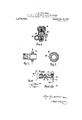
- Fig. 3 is a detail of part of the wave generator.
- Fig. 4 being a section on the line 4-4, Fig. 3.
- Fig. 5 is a section showing the method of connecting the fire-controlling lever and its pump with the main line.
- Fig. 6 is an end elevation
- F 7 is a section of the wave generator.
- Fig. 8 is an end view
- Fig. 9 a section of the trigger motor for operating the firing pin of the gun.
- Fig. 10 is a section showing a modified form of trigger motor.
- F 11 is a detail of Fig. 10, while Fig. 12 is a section on the line 12-12, Fig. 10.
- Fig. 13 shows a general view partly in section of a modified apparatus for controlling machine gun fire between the propellers of an aeroplane.
- impulsive waves obtained by the rotation of a cam driven by an aeroplane engine are used for the purpose of firing a machine gun and so timing the shotsthat they always pass between the propeller blades.
- the engine is caused to drive a generator 31, shown in detail in Figs. 3, 4, and 6, which is connected by a pipe 32 with a trigger motor 33.
- the transmission line is filled with liquid and pressure is put upon the line by a pump contained in the control lever 34, which is connected by a pipe 35 through a cook 36 and controlling .valve 37 with the transmission line joining the generator and motor;
- the control lever 34 illustrated in section in Fig. 2 comprises a handle 38 normally locked relatively to the main portion of the handle 39 by means of balls 40.
- the hollow controlling lever 39 contains paraffin oil, or any very fluid liquid, up to a convenient level and the central rod 41 carriesat its end a piston 44 adapted to put the liquid under pressure in the chamber 45.
- This chamber is connected through the pipe 35.. and cock. 36 with the controlling val-lac e liquid from the chamber 45 is forced under pressure into the chamber 46 and acting against the spring 47 opens the check valve 48 so that pressure is communicated from the chamber 45 through the valve 48 to the main transmission pipe 32.
- the handle 38 is drawn upward relatively to the part 39 the pressure in the chamber 46 falls so that the pressure of the spring 50 causes the bolt head 51 to force the valve 48 downward, thus allowing the pressure to drop in the transmission pipe 32.
- the generator 31 comprises a cam 61 rotated from the engine in any suitable manner.
- This cam acts on apiston 62 so that at every.
- the motor is illustrated in Figs. 8 and 9. It comprises a plunger 71 which operates the machine gun trigger or firing pin or the like. This plunger is held in the rear position by a spring 72 and is provided at its rear end with a piston 73 which is actuated by the arriving impulsive wave.
- a reflected wave absorber -74 comprising a valve having an aperture 75'therethrough and held against its seat by means of a spring 64.
- the wave absorber 74 Upon the impulse traveling along the pipe and reaching the wave absorber 74 the latter is forced away from its seat against the action of the spring and the impulsive wave acts on the piston 73 and so forces the plunger 71 forward against the action of the spring 72 and thus fires the gun. If the energy of the wave is not ab sorbed by the work done on the piston the reflected wave is prevented from traveling back by the valve 74 closing on its seat and the energy reflected is taken up in the passage 7 5.
- a modified form of trigger motor is shown in Figs. 10, 11 and 12.
- the pipe 32 is connected at 76 and the trans-' mitted wave passes through the reflectedwave absorber 77 to the passage 7 8, which is normally closed by the conical valve 79.
- the valve 79 opens the impulslve wave acts on a larger diameter than the diameter of the passage 78 so that a somewhat sharper impulse is given to the plunger 80 of the trigger motor.
- a modified arrangement for firing beterm.
- the generator 87 is driven through a Cardan shaft 88 or any other suitable drive 4 at twice the propeller speed and is lubricated by means of an ordinary drip-feed lubricator 89.
- the wave for firing the gun is transmitted from the generator to the trigger motor by the pipe 32.
- the reservoir by which the'liquid under pressure issupplied is contained in the cylinder. 90, which is connected 'to the main system by the small pipe 91.
- the handle 92 is drawn upward extending the spring 93. The handle is then let go and a store of paraffin oil under pressure is thus obtained in the inner cylinder 94 below the piston 95.
- the gun is now ready for firing, and in order to commence firing when the waves are generated by the generator 87 the Bowden wire lever 96 is pulled.
- the Bowden wire is fixed to the projection 97 at thelower end of the cylinder and pulling on the lever 96 causes the sheath 98 of the Bowden wire to force the pin 99 inward, closing the communication between the pipe 91 and the outer space 100 at the bottom of the cylinder 90 by entering the washer 101 and subsequently pressing on the abutment 102 on the valve 103 and opening communication between the oil under pressure below the piston 95 and the pipe 91.
- Apparatus for the transmission of power comprising: a container for a column of liquid normally under atmospheric pressure, means for applying pressure to said liquidcolumn at the will of the operator to make said column responsive to pressure variations, automatic means for imparting to said liquid column an impulse at timed intervals, said impulse being ineffective except when the column is under pressure, and .an actuating device responsive to the impulse transmitted through the liquid column when the latter is under pressure.
- Apparatus for the transmission of power comprising: a container for a column of liquid normally under atmospheric pressure, means for applying pressure. to said liquid column at the will of the operator to make said column responsive to pressure variations, automatic means for imparting to said liquid column an impulse at intervals, said impulse being inefiective except when the column is under pressure, an actuating device responsive to the impulse transmitted through the liquid column when the latter is under pressure, and means for absorbing the impulse reflected from the actuating device.
- Apparatus for the transmission of power comprising: a container for a column of liquid normally under atmospheric pressure, means for applying pressure to said liquid column at the will of the operator to make said column responsive to pressure variations, automatic means'for imparting to said liquid column an impulse at timed intervals,
- Apparatus for firing a machine gun comprising: a container for a column of liquid normally under atmospheric pressure, means for applying pressure to said liquid column at the will of the operator to make said column responsive to pressure variations, automatic means for imparting to said liquid column an impulse at intervals, said impulse being ineffective except when the column is under pressure, and a trigger motor responsive to the impulse transmitted through the liquid column when the latter is under pressure.
- Apparatus for firing a machine gun comprising: a container for a column of liquid normally under atmospheric pressure, means for applying pressure to said liquid column at the will of the operator to make said column responsive to pressure variations, automatic means for imparting to said liquid column an impulse at intervals, said impulse being ineffective except when the column is under pressure, a trigger motor responsive to the impulse transmitted through the liquid column when the latter is under pressure, and means for absorbing the impulse reflected from the trigger motor.
- Apparatus for firing a machine gun comprising: a container for a column of liquid normally under atmospheric pressure, means for applying pressure to said column of liquid at the will of the operator to make said column responsive to pressure variations, means driven in timed relation with an aeroplane propeller for imparting to said liquid column an impulse at regularly recurring intervals, said impulse bein ineffective except when the column is unc er pressure, and a trigger motor responsive to the impulse transmitted through the liquid column when the latter is under pressure.
- Apparatus for firing a machine gun comprising: a container for a column of liquid normally under atmospheric pressure, means for applying pressure to said column of liquid at the will of the operator to make ring intervals, said impulse being ineffective 1 except when the column is under pressure, a trigger motor responsive to. the impulse transmitted through the liquid column when the latter'is under' pressure, and means for absorbing the impulse reflected from. the T trigger motor.
Landscapes
- Engineering & Computer Science (AREA)
- General Engineering & Computer Science (AREA)
- Nozzles (AREA)
Description
G. CONSTANTINESCO.
METHOD AND MEANS FOR ACTUATING GUN TRIGGERS.
APPLICATION FILED SEPT-4. 1 917. RENEWED on. 5. 1920.
1,372,944. Patented Mar. 29, 192
4 SHEETS-SHEET G. CONSTANTINESCO.
METHOD AND MEANS FOR ACTUA'TING GUN TRIGGERS. APPLICATION-FILED SEPT. 4, 1911. RENEWED OCT. 5, 1920.
1,372,944. Patented Mar. 29, 1921. 4 SHEETSSHEET 2.
G. CONSTANTINESCO. METHOD AND MEANS FOR ACTUATING GUN TRIGGERS.
APPLICATION FILED SEPT- 4. 1917.
RENEWED OCT- 5,1920. 7
Patented Mar. 29, 1921.
4 SHEETSSHEET 3.
ll/ll/J I 7//////// i.
. ///////////I/l/ .zlrlllflllllllzl \V V G. CONSTANTINESCO. METHOD AND MEANS FOR ACTUATING GUN TRIGGERS.
APPLICATION FILED SEPT. 4. 1917.
RENEWED OCT. 5, 1920.
Emma Mar. 29, 1921.
4 SHEETSSHEET 4.
? ffi yx g st GOGU CONSTANTINESOO, OF WEYBRIDGE, ENGLAND, ASSIGNOR OF ONE-HALF TO WALTER HADDON, OF LONDON, ENGLAND.
METHOD AND MEANS FOR ACTUATING GUN-TRIGGERS.
Specification of Letters Patent. Patented M 29 1921 Application filed September 4, 1917, Serial No. 189,645. Renewed October 5, 1920. Serial No. 414,833.
To all whom may concern:
Be it known that I, GocU CONSTANTINESOO,
, a subject of the King of Great Britain and Ireland, formerly a subject of the King of Roumania, residin at Carmen Sylva, Beechwood avenue, atlands Park, Weybridge, in the country of Surrey, England, formerly residing at Westoe, Stanley avenue, Alperton, in the county of Middlesex, England, have invented a certain new and useful Im roved Method and Means for Actuating un-Triggers, of which the following is a specificatlon.
The present invention relates to a method of and apparatus for actuating gun triggers by liquid wave transmission of the type de-' scribed in the specifications of British Letters Patent Nos. 9029 of 1913, and 9930 of 1916, and is especially applicable for actuating machine gun triggers which are required to be actuated at precise instants, particularly for machine guns firing through the propellers on aeroplanes at intervals determined by the speed of the propeller shaft. For this purpose it is only necessary to drive the cam of a liquid wave generator from the engine, the cam operating to produce impulses which travel along a liquid column as described in my application for British Letters Patent No. 9930 of 1916 and which actuate the trigger.
The invention consists in a method of and means for firing machine guns so that each shot passes between the blades of the rotating propeller 'by wave impulses transmitted from a generator driven by the engine which drives the propeller.
The invention also consists in the improved means for firing machine guns mounted on aeroplanes hereinafter described.
Referring to the accompanying drawings:
Figure 1 shows the general arrangement of a method of employing the invention for actuating a machine gun trigger for firlng between the propeller blades of an aeroplane.
Fig. 2 is a section showin the controlling handle of the aeroplane modified to provide a fire-controlling device.
Fig. 3 is a detail of part of the wave generator.
Fig. 4 being a section on the line 4-4, Fig. 3.
37, illustrated in detail in Fig. 5.
Fig. 5 is a section showing the method of connecting the fire-controlling lever and its pump with the main line.
Fig. 6 is an end elevation, and
F 7 is a section of the wave generator.
Fig. 8 is an end view, and
Fig. 9 a section of the trigger motor for operating the firing pin of the gun.
Fig. 10 is a section showing a modified form of trigger motor.
F 11 is a detail of Fig. 10, while Fig. 12 is a section on the line 12-12, Fig. 10.
Fig. 13 shows a general view partly in section of a modified apparatus for controlling machine gun fire between the propellers of an aeroplane.
In the form of the invention shown in Figs. 1 to 9, impulsive waves obtained by the rotation of a cam driven by an aeroplane engine are used for the purpose of firing a machine gun and so timing the shotsthat they always pass between the propeller blades. For this purpose the engine is caused to drive a generator 31, shown in detail in Figs. 3, 4, and 6, which is connected by a pipe 32 with a trigger motor 33. The transmission line is filled with liquid and pressure is put upon the line by a pump contained in the control lever 34, which is connected by a pipe 35 through a cook 36 and controlling .valve 37 with the transmission line joining the generator and motor; The control lever 34, illustrated in section in Fig. 2 comprises a handle 38 normally locked relatively to the main portion of the handle 39 by means of balls 40. I
balls can move inward allowing the handle 38 to be pressed downward relatively to the portion 39 of the controlling lever. The hollow controlling lever 39 contains paraffin oil, or any very fluid liquid, up to a convenient level and the central rod 41 carriesat its end a piston 44 adapted to put the liquid under pressure in the chamber 45. This chamber is connected through the pipe 35.. and cock. 36 with the controlling val-lac e liquid from the chamber 45 is forced under pressure into the chamber 46 and acting against the spring 47 opens the check valve 48 so that pressure is communicated from the chamber 45 through the valve 48 to the main transmission pipe 32. When the handle 38 is drawn upward relatively to the part 39 the pressure in the chamber 46 falls so that the pressure of the spring 50 causes the bolt head 51 to force the valve 48 downward, thus allowing the pressure to drop in the transmission pipe 32.
It will be seen, therefore, that when the handle 38 is pressed downward the pressure generated in the pump cylinder 45 will be transmitted to the transmission line keeping this under a definite pressure above atmosphere. When the handle 38 is lifted the pressure in the transmission line is released through the valve 48 which remains open. The generator 31 comprises a cam 61 rotated from the engine in any suitable manner.
This cam acts on apiston 62 so that at every.
revolution of the cam the projection 563 causes a downward movement of the plston 62-. If there is pressure in the transmission lihe 32 this downward movement of the piston generates an impulsive wave in the liquid in the pipe 32 and this impulsive wave travels along the pipe until it reaches the motor 33.
The motor is illustrated in Figs. 8 and 9. It comprises a plunger 71 which operates the machine gun trigger or firing pin or the like. This plunger is held in the rear position by a spring 72 and is provided at its rear end with a piston 73 which is actuated by the arriving impulsive wave. At the rear of the trigger motor there is provided a reflected wave absorber -74 comprising a valve having an aperture 75'therethrough and held against its seat by means of a spring 64. Upon the impulse traveling along the pipe and reaching the wave absorber 74 the latter is forced away from its seat against the action of the spring and the impulsive wave acts on the piston 73 and so forces the plunger 71 forward against the action of the spring 72 and thus fires the gun. If the energy of the wave is not ab sorbed by the work done on the piston the reflected wave is prevented from traveling back by the valve 74 closing on its seat and the energy reflected is taken up in the passage 7 5. v
A modified form of trigger motor is shown in Figs. 10, 11 and 12. In this form the pipe 32 is connected at 76 and the trans-' mitted wave passes through the reflectedwave absorber 77 to the passage 7 8, which is normally closed by the conical valve 79. Immediately the valve 79 opens the impulslve wave acts on a larger diameter than the diameter of the passage 78 so that a somewhat sharper impulse is given to the plunger 80 of the trigger motor.
A modified arrangement for firing beterm. The generator 87 is driven through a Cardan shaft 88 or any other suitable drive 4 at twice the propeller speed and is lubricated by means of an ordinary drip-feed lubricator 89. The wave for firing the gun is transmitted from the generator to the trigger motor by the pipe 32. In this modification the reservoir by which the'liquid under pressure issupplied is contained in the cylinder. 90, which is connected 'to the main system by the small pipe 91. In order to put pressure on the transmission system and cause the gun to be fired, the handle 92 is drawn upward extending the spring 93. The handle is then let go and a store of paraffin oil under pressure is thus obtained in the inner cylinder 94 below the piston 95. The gun is now ready for firing, and in order to commence firing when the waves are generated by the generator 87 the Bowden wire lever 96 is pulled. The Bowden wire is fixed to the projection 97 at thelower end of the cylinder and pulling on the lever 96 causes the sheath 98 of the Bowden wire to force the pin 99 inward, closing the communication between the pipe 91 and the outer space 100 at the bottom of the cylinder 90 by entering the washer 101 and subsequently pressing on the abutment 102 on the valve 103 and opening communication between the oil under pressure below the piston 95 and the pipe 91. In this way, 'by pulling the handle 96 of the Bowden wire device, pressure is transmitted to the transmission line, with the result that .as the cam in the generator 87 rotates a series of impulsive waves are transmitted along the pipe 32 and'operate the trigger motor 81. The plunger 83 of the trigger motor will thus at every half revolution of the propeller cause a for ward movement of the plunger 83, firing the gun if the firing bar is in the correct position for firing. By this means the firing of each shot is timed so that it misses the propeller and it is found that the difference of time taken by the wave to travel from the generator to the.trigger motor at difierent speeds is so small that there is no danger of hitting the propeller for a large range of speeds of the engine. Should it happen that an impulse arrives at the trigger motor being fired, the lever 84 simply moves withliquid column at the will of the operator to make said column responsive to pressure variations, automatic means for lmpartlng to sald liquid column an impulse at lntervals,
said impulse being ineffective except when the column is under pressure, and an actuating device responsive to the impulse transmitted through the liquid column when the latter'is under pressure.
3. Apparatus for the transmission of power comprising: a container for a column of liquid normally under atmospheric pressure, means for applying pressure to said liquidcolumn at the will of the operator to make said column responsive to pressure variations, automatic means for imparting to said liquid column an impulse at timed intervals, said impulse being ineffective except when the column is under pressure, and .an actuating device responsive to the impulse transmitted through the liquid column when the latter is under pressure.
4. Apparatus for the transmission of power comprising: a container for a column of liquid normally under atmospheric pressure, means for applying pressure. to said liquid column at the will of the operator to make said column responsive to pressure variations, automatic means for imparting to said liquid column an impulse at intervals, said impulse being inefiective except when the column is under pressure, an actuating device responsive to the impulse transmitted through the liquid column when the latter is under pressure, and means for absorbing the impulse reflected from the actuating device.
5. Apparatus for the transmission of power comprising: a container for a column of liquid normally under atmospheric pressure, means for applying pressure to said liquid column at the will of the operator to make said column responsive to pressure variations, automatic means'for imparting to said liquid column an impulse at timed intervals,
said impulse being ineffective except when the column is under pressure, an. actuating device responsive to the impulse transmitted through the liquid column when the latter is under pressure,'and means for absorbing the impulse reflected from the actuating device.
6. Apparatus for firing a machine gun comprising: a container for a column of liquid normally under atmospheric pressure, means for applying pressure to said liquid column at the will of the operator to make said column responsive to pressure variations, automatic means for imparting to said liquid column an impulse at intervals, said impulse being ineffective except when the column is under pressure, and a trigger motor responsive to the impulse transmitted through the liquid column when the latter is under pressure.
7. Apparatus for firing a machine gun comprising: a container for a column of liquid normally under atmospheric pressure, means for applying pressure to said liquid column at the will of the operator to make said column responsive to pressure variations, automatic means for imparting to said liquid column an impulse at intervals, said impulse being ineffective except when the column is under pressure, a trigger motor responsive to the impulse transmitted through the liquid column when the latter is under pressure, and means for absorbing the impulse reflected from the trigger motor.-
8. Apparatus for firing a machine gun comprising: a container for a column of liquid normally under atmospheric pressure, means for applying pressure to said column of liquid at the will of the operator to make said column responsive to pressure variations, means driven in timed relation with an aeroplane propeller for imparting to said liquid column an impulse at regularly recurring intervals, said impulse bein ineffective except when the column is unc er pressure, and a trigger motor responsive to the impulse transmitted through the liquid column when the latter is under pressure.
'9. Apparatus for firing a machine gun comprising: a container for a column of liquid normally under atmospheric pressure, means for applying pressure to said column of liquid at the will of the operator to make ring intervals, said impulse being ineffective 1 except when the column is under pressure, a trigger motor responsive to. the impulse transmitted through the liquid column when the latter'is under' pressure, and means for absorbing the impulse reflected from. the T trigger motor.
In testimony whereof I have signed my name to this specification.
GOGU CONSTANTINESCO.
Priority Applications (1)
| Application Number | Priority Date | Filing Date | Title |
|---|---|---|---|
| US189645A US1372944A (en) | 1917-09-04 | 1917-09-04 | Method and means for actuating gun-triggers |
Applications Claiming Priority (1)
| Application Number | Priority Date | Filing Date | Title |
|---|---|---|---|
| US189645A US1372944A (en) | 1917-09-04 | 1917-09-04 | Method and means for actuating gun-triggers |
Publications (1)
| Publication Number | Publication Date |
|---|---|
| US1372944A true US1372944A (en) | 1921-03-29 |
Family
ID=22698197
Family Applications (1)
| Application Number | Title | Priority Date | Filing Date |
|---|---|---|---|
| US189645A Expired - Lifetime US1372944A (en) | 1917-09-04 | 1917-09-04 | Method and means for actuating gun-triggers |
Country Status (1)
| Country | Link |
|---|---|
| US (1) | US1372944A (en) |
Cited By (3)
| Publication number | Priority date | Publication date | Assignee | Title |
|---|---|---|---|---|
| US2491375A (en) * | 1944-03-28 | 1949-12-13 | Marquette Metal Products Co | Propeller mechanism and control |
| US4004488A (en) * | 1975-04-01 | 1977-01-25 | The United States Of America As Represented By The Secretary Of The Navy | Dual-motion firing device |
| CH669993A5 (en) * | 1986-04-15 | 1989-04-28 | Oerlikon Buehrle Ag | Electromagnetic trigger release for automatic weapon - uses hydraulic system with manual pump and pedal operated switches to operate release piston |
-
1917
- 1917-09-04 US US189645A patent/US1372944A/en not_active Expired - Lifetime
Cited By (3)
| Publication number | Priority date | Publication date | Assignee | Title |
|---|---|---|---|---|
| US2491375A (en) * | 1944-03-28 | 1949-12-13 | Marquette Metal Products Co | Propeller mechanism and control |
| US4004488A (en) * | 1975-04-01 | 1977-01-25 | The United States Of America As Represented By The Secretary Of The Navy | Dual-motion firing device |
| CH669993A5 (en) * | 1986-04-15 | 1989-04-28 | Oerlikon Buehrle Ag | Electromagnetic trigger release for automatic weapon - uses hydraulic system with manual pump and pedal operated switches to operate release piston |
Similar Documents
| Publication | Publication Date | Title |
|---|---|---|
| US3189015A (en) | Magazine and target feeding apparatus | |
| US1351141A (en) | Buffer | |
| US2116860A (en) | Automatic gun charger | |
| US1372944A (en) | Method and means for actuating gun-triggers | |
| US2455845A (en) | Rocket | |
| US2750890A (en) | Time delay fuze for a mine | |
| US1976903A (en) | Lubricating device | |
| US2147550A (en) | Projectile | |
| US2391636A (en) | Gun | |
| US2498697A (en) | Hydraulic starting mechanism | |
| US1951032A (en) | Engine starting mechanism | |
| US2316394A (en) | Explosive type engine | |
| US2411290A (en) | Machine gun synchronizer | |
| US2154555A (en) | Engine starting apparatus | |
| US1788288A (en) | Oil-injection apparatus for internal-combustion engines | |
| US1518355A (en) | Device for moderating the speed of discharge for automatic firearms | |
| US2258159A (en) | Engine starter gearing | |
| RU2721215C1 (en) | Pneumatic hydraulic catapult | |
| US3391602A (en) | Frequency responsive lubrication system | |
| US1504394A (en) | Synchronizing gun control | |
| US2865172A (en) | Rotary reaction engine | |
| US2215103A (en) | Drive transmission | |
| US1562424A (en) | Control mechanism for aircraft guns | |
| US2920534A (en) | Dud jettisoning device | |
| US1504713A (en) | Flexible-shaft synchronizing gear |