US1354591A - Electric machine - Google Patents
Electric machine Download PDFInfo
- Publication number
- US1354591A US1354591A US316584A US31658419A US1354591A US 1354591 A US1354591 A US 1354591A US 316584 A US316584 A US 316584A US 31658419 A US31658419 A US 31658419A US 1354591 A US1354591 A US 1354591A
- Authority
- US
- United States
- Prior art keywords
- wire
- brush
- transformer
- rectifying
- wires
- Prior art date
- Legal status (The legal status is an assumption and is not a legal conclusion. Google has not performed a legal analysis and makes no representation as to the accuracy of the status listed.)
- Expired - Lifetime
Links
- 238000004804 winding Methods 0.000 description 88
- 238000010438 heat treatment Methods 0.000 description 15
- 230000001360 synchronised effect Effects 0.000 description 15
- 230000007246 mechanism Effects 0.000 description 11
- 230000009471 action Effects 0.000 description 6
- 230000000694 effects Effects 0.000 description 5
- 239000004020 conductor Substances 0.000 description 3
- 230000001276 controlling effect Effects 0.000 description 3
- 238000010586 diagram Methods 0.000 description 3
- 238000006073 displacement reaction Methods 0.000 description 3
- 230000005611 electricity Effects 0.000 description 3
- 238000009413 insulation Methods 0.000 description 3
- 230000002093 peripheral effect Effects 0.000 description 3
- 230000008859 change Effects 0.000 description 2
- 230000009467 reduction Effects 0.000 description 2
- 230000001105 regulatory effect Effects 0.000 description 2
- 230000017105 transposition Effects 0.000 description 2
- 101100001677 Emericella variicolor andL gene Proteins 0.000 description 1
- 241000966334 Simias Species 0.000 description 1
- 230000015572 biosynthetic process Effects 0.000 description 1
- 230000003292 diminished effect Effects 0.000 description 1
- 230000001939 inductive effect Effects 0.000 description 1
- 238000004519 manufacturing process Methods 0.000 description 1
- 230000008439 repair process Effects 0.000 description 1
- 230000004936 stimulating effect Effects 0.000 description 1
- 230000009466 transformation Effects 0.000 description 1
- 230000001052 transient effect Effects 0.000 description 1
- 239000002699 waste material Substances 0.000 description 1
Images

Classifications
-
- H—ELECTRICITY
- H05—ELECTRIC TECHNIQUES NOT OTHERWISE PROVIDED FOR
- H05G—X-RAY TECHNIQUE
- H05G1/00—X-ray apparatus involving X-ray tubes; Circuits therefor
- H05G1/08—Electrical details
- H05G1/58—Switching arrangements for changing-over from one mode of operation to another, e.g. from radioscopy to radiography, from radioscopy to irradiation or from one tube voltage to another
Definitions
- My invention relates to electric machines for developing, rectifying and distributing currents of high potential.
- my invention relates to machines of the kind just mentioned and admits of general use, but is peculiarly adapted for use in connection with X-ray tubes and other vacuum tubes, and especially in instances where the tube is to be subjected to the action of a number of different electric currents, applied to it for the purpose of affecting it in different ways.
- Vhat l seek primarily to do, therefore, is to produce a unitary machine adapted to supply Veach and all of the number and variety of currents required to operate au X- ray tube of any kind, and in which the currents may within'reasonable limits be varied as to number and variety, each kind of current being controllable independently of others.
- V To provide the machine with means for enabling the operator to time the ignition currents relatively to the main discharges; or in other words, to adjust the lag or lead of the ignition.
- Vl Vl.
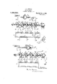
- Figure l is a diagram showing my inven- .tion as used in connection with an X-ray tube of the kind known as an ignition tube or Lilienfeld tube, the secondary windings of the main transformer being in series with each other.
- Fig. 2 is a wiring diagramshowing how the secondary windings of the main transformer may be connected together in parallel with each other.
- Fig. 3 is a diagram showing my invention as used with a Coolidge tube, that is, an X- ray tube in which the cathode is heated to incandescence independently of the heating effect of the main discharge through the tube. f'
- Fig. 4 is a diagram showing my invention o as employed in connection with an ordinary X-ray tube containing rareed gas and known commercially as a gas tube.
- Three transformers appear at. 12, 13'* and 14, and are herein designated according to their respective uses.
- the primary winding 16 is by two wires 21, 22, together with a variable resistance 23 and a variable inductance-24,
- the ignition transformer is provided with a ⁇ primary winding 25 and -a secondary Winding 26.
- the primary winding 25 is by wires 27, 28, together with a variable resistance 29 and a variable inductance-30, connected with the feed wires 5, 6.
- the purpose of the ignition transformerv13 is to force a high tension current through 'a por- .tion of the X-ray tube 15, in order to. es-
- the heating transformer 14 is provided with a primary winding 31 and with a secondary winding 32.' The primary winding 31 is by means of wires 33, 34, together with Va variableresistance 35 and a variable in- .ductance 36, connected with the 'feed wires 5, 6.
- variable resistances and the variable inductances are used for the purpose of regulating and controlling the various devices with which they are as sociated, and need not be further described.
- The' synchronous motor 9 is provided with Y a. revoluble shaft37 having considerable coV ' 40, 41 and 42 always remain'xed relatively length 'andengaging a* bearing 38. This shaftis fitted into the 'collar 10, and'. se-
- thel shaft 37 is as a unit adjustable tor.- o l
- Mounted upon the shaft 37 and revoluble therewith are disks, 39, 40, 4.1, 42 and 43, in this instance fivel in number.
- the disk 43l is normally larl relatively to the'mopurposes of the main discharge, and is an fixed relatively to said shaft.
- the disk 43 is provided with a collar 44, carrying a set screw 45, and is-adjustable relatively to the shaft. That is to say, the op. ⁇
- the disks are provided with contact sectors 46, 47, 48, 49, 50, 51, 52, 53, 54, and 55, these contact sectors being disposed in pairs, each disk carrying one pair.
- Located adjacent the disks are a number of stationary contact brushes 56,57, 58, 59, 60, 61, 62, 63, 64, 65 66, 67, 68, 69, 70, 71,
- Each contact sector is of sumcient length to reach from one contact brush to the next.
- the contact sector 46 is of proper length to establish' connection between the brushes- 56 and 57, or between the brushes 57 and 58, or between the brushes 58 and 59, .or between the brushes 59 and 56.
- a wire 76 extends from the brush 59 t0. the brush 63. from the brush 61 to the brush 65.
- Simia wire 78 extends from the brush '67 to t e brush 71.
- a wire 79 leads from the biush 57 to the X-ray tube 15 and is 'connected to the anode
- the tube contains a heating filament 81, from which a wire 82 leads to the secondary winding 32 of the heating transformer 14.' Two wires 83 and 84 lead Another wire 77 extends from the secondary winding32 back to ⁇ the heating filament l81.
- a wire 85 isjconnected with the'wires 83'and 84, and leads therefrom to the brush 73.
- a wire' 86 leads from the secondary. winding 26 of the-ignition transformer ⁇ 13 to the brush 74, and a wire 87 leads from the brush -7 2 to the secondary winding 26.
- -A wire 88 is connected to the brush 75 and to two wires 89 and 90, thefwire 90 leadin to the ground at 91, and the wire 89'lea ing to the brush 69. 0r, the ground wire 90 maybe .omitted and the wire 77 grounded.
- a wire 92 leads from thefbrush 69 to a terminal 93 of the X-ray tube,
- the terminal 93 is a cathode-terminal for anode terminal for purposes of the so-called 1 ition discharge-that is, Ythe glow dis'- ed filament 81, which isgalways a cathode.
- the ignition discharge just mentioned is due to a. high voltage current from the secondaryV winding 26 of the ignition transformer 13.
- the various secondary windings 17, 18, 19 and 20 of the main transformer are by wires 94, 95, 96, 97, 98, 99, 100 and 101 connected with the respective brushes 56, 58, 60, 62, 64 66, es, 7o, 72 and 74.
- the synchronous motor 9 niakes 1800 revolutions per minute, and the feed wires 5, 6 are supplied with alternating currents of sixty cycles per second, or 3600 cycles per minute.
- the shaft 37 makes onehalf of a complete revolution during each cycle, so that each transformer winding generates four currents (two'in each direction) while the rectifier disks each make one complete revolution.
- These currents are yrectified by the action of the rectifying disks, so that they all pass in a unitary direction through the X-ray tube, so as to cause the production of the X-rays.
- the primary circuit for the heating transformer 14 is as follows: feed wire 6, wire 34, primary winding 31, wire 33, variable inductance 36, variable resistance 35, feed wire 5 to source of electricity (not shown), thence back to feed wire 6.
- the secondary circuit of the heating transformer 14 may be traced as follows: secondary winding 32, wires83 and 84, lament 81, and wire 82 back to secondary winding 32. This circuit heats the filament 81, which as elsewhere explained is always a cathode.
- the circuit through the synchronous motor 9 may be traced as follows: feed wire 6, wire 8, synchronous motor 9, wire 7, feed wire 5 to source of electricity (not shown), thence back to feed wire 6. y
- the primary circuit of the ignition transformer 13 may be traced as follows: feed wire 6, wire 28 to primary winding 25, wire 27, variable inductance 30, variable resistance 29, feed wire 5 to source of electricity, thence back to feed wire 6.
- a secondary circuit of the ignition transformer 13 may be traced as follows: secondary winding 26, wire 86, brush 74, contact sector 55, brush 75, wires 88 and 89 (these two wires being grounded at 91 through ground wire 90), brush 69, wire 92, I
- terminal 93 (serving for purposes .of this circuit as an anode), through adjacent portion of X-ray tube to filament 81 (serving as a cathode), wires 84 and 85, brush 73, contact sector 54, brush 72 and wire 87 back to secondary winding 26.
- the ignition circuits all cause discharges to pass from the filament 81 to the terminal 93, through the adjacent portion of the X- ray tube, these discharges all taking place in the same direction relatively to the tube, and serving to perform the step known in this art as ignition.
- the primary circuit through the main transformer 12 is as follows: feed wire 6, wire 22, primary winding 16, wire 21, inductive resistance 24, variable resistance 23, feed wire 5 to source of supply (not shown), thence back to feed wire 6.
- ⁇ 'disk are. of course transposed relatively to each other.v
- the contactl sectors 46 and 47 merelychange places with each other. At the'instant this occurs each transformer 'hasthe same polarity it -had atrst-that is, the polarity contemplated by thevv condition of the apparatus as illustratedl in Fig.4 1.
- SuchV beingjthe'fcaseffitis obvious t' t a 'circuit can' now -traced through the secondary windings ofthe main transformer Aand .through the .X-.r'ay' tube,-
- the wire 79a is connected to a wire 102 which leads to the brush 57.
- Awire 1.03 is connectedto the two wires 7 9a and 102, and is also connected lto two other wires 104 and 105.
- the wire 105 is connected .to the brush 65.
- the wire 104 is connected toA two wir 106 and 107, the wire 106 leading to the rush 63 and the wire 107 leading to the brush 71.
- the wire92a is connected to two wires 108 and 109, ,thegwire 108 leading to the brush 69 and the wire 109 being connected to two Y wires 110 and 111.
- the wire 110 leads to the brush 61,'.and the wire 111 is connected roe to two other wires 112 and 113. rlhe wire 112 'is connectedwith'the brush 67, the wire -113'leading to the brush59.
- the second circuit is as follows: secondary winding 18, wire 96, brush 60, 4contact sector 48, brush 63, wires 106, 104, 103, wire 79a to X-ray tube, back by wire 92, wires 109, 110, brushk 61, contact sector 49. brush 62 and wire 97 back to secondary winding 18.
- the third circuit is as follows: secondary winding 19, wire 98, brush 64, contact sector 50. brush 65, wires 105. 103, wire 79a to X-ray tube, back by wire 92a, wires 109, 111 andL 112 to brush 67 contact sector 51, brush 66 and wire 99, back to secondary winding 19.
- the fourth circuit is as follows: secondary winding 20, wire 100, brush 68, contact sec-tor 52,. brush 71, wires 107, 104 and 103, wire 79a to X-ray tube, thence back by wire 92, wire 108, brush 69, contact sector 53, brush 70, and wire 101 back to second-'ary winding 20.
- the circuit through the secondary winding 17 is as follows: secondary winding 17, wire 95, brush 58, Contact sector 46, contact sector 46 (now in a new osition) brush 57, wire 102, wire 79a to -ray t-ube, thence back by wire 92a, -wires 109, 111 and 113, brush 59, contact sector 47 (in a new position), brush 56 and wire 94, back to secondary wiuding 17.
- the circuitl through the secondary winding 18 is as follows: secondary winding 18, wire 97, brush 62, contact sector 49 (now in a new position), brush 63, wires 106, 104 and 103, wire 79a to X-ray tube, thence back by wire 92a, wires 109, 110 ⁇ brush 61, contact sectorU 48 (in a new position), brush 60 and Wire 96 back to secondary winding 18.
- the circuit through the secondary winding 19 is as follows: secondaryV Winding 19,
- the circuit through the secondary wind- 'anode to a heated cathode.
- each disk during each revolution virtually reverses the direction of the current from one secondary winding. so that the current from each secondary winding is rectified as often as it is reversed by the action of the transformer.
- connections to the brushes can be arranged in other ways than those aboredescribed, so as to obtain different ratios of potential as compared with current.
- the connections can be arranged in multiple-series rather than in series or in parallel as described. l do not deem it necessary to show or Adescribe such variations in the connections, or to pursue further the practical effects thereof. as the subject here drifts off into engineering and mechanical skill.
- Fig. 3 my device is shown as used in connection with a so-called Coolidge tube, that is, an X-ray tube in which the single discharge in the tube takes place from the shown at 114, and has the form of a glowing ilament.
- the anode appears at 80a, a wire 79b leading to it in the same manner
- This cathode is and for the same purpose that in Fig. 1
- the wire 79 leads to the anode 80.
- a wire 92" is connected withthe cathode 114, and leads therefrom to the brush 69. thus corresponding to the wire 92 in Fig. 1.
- the wire 921 is connected -to a wire 115, the latter be- ⁇ ing connectedto a wire 116 which is grounded at 117, as,v shown, or Vwhich may be grounded at 77.
- the groundwire 116 and the wire 115 are connected to a wire 118, leading to the brush 75.
- a wire 119 leads from the cathode 114 to the brush 73.
- the cathode 114 is heated by currents from the transformer 13.
- the primary winding 25 is by a Wire 27* v pearing in Fig. 2
- cathode 114 may be traced as. follows: sec-v ondary winding 26, wire 87, brush 72, contact sector 54, brush 73, wire 119, cathode 114, wire 115, ⁇ wires 116 and 118 (the wire 116 being grounded), brush 75, contact sector 55, brush 74 andy wire 86 back to secondary winding 26.
- the circuit through the cathode may be traced as follows: secondary winding 26, wire 86, brush 74, contact sector 54 (now in a new position),brush 73,
- the currents for heating the cathode shown at 114 in Fig. 3 are of the same character as those used for setting up discharges from the terminal 93, considered as an anode, and the cathode 81.
- Such currents4 thusused are for the purpose of ignition. They are almost, b ut not exactly, in s nchronism with the currents from the secon ary windings of the main transformer. That is to say, they are given a slight lead as compared with the secondary currents" of the main transformer, in order that the ignition discharge may-act as a pilot control for the'main discharge.
- the lead thus/given to the ignition discharge is regulated, at the will of the operator, by manual adjustment ofthe disk '43 upon'the shaft 37.
- the adjustment is accompllshed by loosening the bolt ⁇ y45, turning ⁇ the disk slightly upon the shaft, and ti hteni ing the bolt. This leaves the disk 43'sl1ghtly displaced relatively to the other disks.
- the adjustment just described is also useful for adapting the machine for use under different degrees of inductancepresented by the secondary windings of the main transformer, as for instance when these windings are operated sometimes in series and at other times in parallel. Again, with changes of speed, changes of current,- changes of potential and changes in manyy other factors,
- the only transformer here used is the main transformer 12.
- the operator connects the windings for high potential and little current, or for lower potential and more current, as desired. ⁇ 1f he uses the ignition circuit, he makes an adjustment for the purpose of ltiming the ignition discharges relatively to the main discharges. a
- the apparatus above described has many advantages.
- the secondary of the main transformer being built up of distinct sections, its, various parts are readily accessiblel for repair and replacement, and are to some extent interchangeable. These, secondary windings may be treated as units, the number of which may be increased within limits permitted by the' size of the machine, 'or may be diminished as desired.
- My device is compact, and can be built comparatively light and strong. its parts admit of standardization to a considerable extent.
- An electric machine of the character described comprising a transformer provided with a primary winding and a plurality of secondary windings, a plurality of rectifying disks, one for each secondary winding, connections vfrom said secondary windings to said rectifying disks, conductors for connectingr said rectifying disks with the main' terminals of an X-ray tube, a motor provided with a revoluble shaft for turning said rectifying disks, an ignition circuit for energizing a portion of said X-ray tube, and an additional disk connected with said revoluble shaft and controllable by rotation thereof for timing said ignition circuit relatively to discharge between the main terminals of said X-ray tube.
- a device of the character described comprising a secondary circuit, revoluble rectifying disks connected with said secondary circuit for rectifying the currents thereof, an additional secondary circuit, an
- additional rectifying disk connected withsaid additional secondary circuit-for rectifying the currents of the same, a revoluble shaft carrying all of said rectifying disks, and means for enabling' the operator at will to adjust said additional rectifying disk by giving it a slight angular displacement relatively to the first mentioned disks.
- a ditional secondary circuit a shaft connected with all of said disks and revoluble, for the purpose of actuating the same, means controllable at the will of the operator for enabling him to give said additional rectifying disk an angular displacement relatively to the first mentioned disks, and aheating member connected to said ignition circuit for the purpose ofinfluencing the ignition discharge, and means for heating said heating member independently of any heating effect of said ignition discharge.
- a device of the character described comprising a main transformer-provided with a primary winding and with a plu-r rallty of secondary windings, a plurality of rectifying disks for rectifying the currents generated by said secondary windings, a plurality of transient .conductors controllable at the will of the operator for connecting said secondary windings with said rectifying disks in a plurality of different ways in order to change the.
- A. Adevice of the character described comprising a main transformer, an ignition transformer, a synchronous motor, means for energizing said'main transformer and said ignition transformer synchronously with said synchronous motor, a revoluble shaft for said synchronous motor, a plurality of rectifying disks mounted Aupon said shaft and revoluble therewith,
- device of the character described comprising a main transformer, an ignition transformer, a heating transformer, a synchronous motor, means for energizing all of said transformers synchronously with said motor, a group of rectifyin devices,
- an X-ray tube provided with a pair of main dischargeJ terminals and further provided with an auxiliary terminal in the form of anv electric conductor ⁇ and adapted to 'be heated in vorder to v in order to energize them for the main disv reduce the resistancebetween said main discharge terminals, a main transformer connected with said main discharge terminals charge, means for electrically energizing said auxiliary terminal in order to' heat the same, a main transformer-for supplying secondary currents to the main discharge terminals, rectifying devices for rectifyin said secondary currents, an ignition trans ormer for supplying secondary currents toa pair of terminals, one bein said auxiliary terminal and the other being one of said main.
- a synchronous motor i auxiliary terminal in the form of a heated cathode for the purpose of reducing the resistance between said main discharge terminals, a main transformer. in electrical communication with said main discharge terminals in order to energize them for the main discharge, an ignition transformer in electrical communication with said auxiliary terminal and 'one of said main discharge terminals for setting up therebetween an igniton discharge for controlling the main discharge, rectifying .disks connected with said main transformer, an additional rectifying disk connected with said ignition transformer, a revoluble shaft carrying all of said vrectifying disks, a synchronous motor connected with said revoluble shaft for actuating said rectifying disks, and
Landscapes
- X-Ray Techniques (AREA)
Description
R. H. wAPPLER.
ELECTRIC MACHINE.
APPLICATION FILED AUG. Il. 1919. A. 1,354,591, Patented oet. 5,1920.
2 SHEETS-SHEET l.
IguRa l. /5
@noaa/Lto@ smHoLn H WAPPLER ai, Mg Gfbtofmziv @mgm An. H
. WAPPLER.
ELECTRIC MACHlNE.
APPLICATION FILED AUG. II, |919.
Patented Oct. 5, 1920.
RsmHoLD H. WAPPLER @513C kiff? CCozmegr 7/1/ um AMM@ UNITED STATES PATENT OFFICE.
REINHOLD H. WAPPLER, OF YONKERS, NEW YORK, ASSIGNOR TO WAPPLER ELECTRIC COMPANY, INC., A CORPORATION 0F NEW YORK.
ELECTRIC MACHINE.
Application l'ed August 11, 1919.
T o all 'whom t may concern.: l
Be it known that I, REINHoLn H. TVM- rmnz, a citizen of the United States, residing at Yonkers, county of Westchester, and State of New York, have invented certain new and useful' Improvements in Electric Machines, of which the following is a full, clear, and concise description.
My invention relates to electric machines for developing, rectifying and distributing currents of high potential.
More particularly stated, my invention relates to machines of the kind just mentioned and admits of general use, but is peculiarly adapted for use in connection with X-ray tubes and other vacuum tubes, and especially in instances where the tube is to be subjected to the action of a number of different electric currents, applied to it for the purpose of affecting it in different ways.
In this connection it may be noted that the development of X-ray apparatus along the lines of increased efficiency has been accompanied by some complications, among them being the elaboration of the tube structure and the addition of electrical devices extraneous to the tube, yet connected therewith and acting upon different parts thereof, and for purposes more or less independent of each other. Hence some X-ray tubes require currents of three kinds, others require currents of two kinds, and still others quire currents of only one kind.
Vhat l seek primarily to do, therefore, is to produce a unitary machine adapted to supply Veach and all of the number and variety of currents required to operate au X- ray tube of any kind, and in which the currents may within'reasonable limits be varied as to number and variety, each kind of current being controllable independently of others.
In producing a machine for the general purpose just indicated, l also seek to obtain a number of distinct advantages, among them being the following:v
I. To so construct and arrange the machine that a single source of alternating current may be used not only to drive the machine but also t'o supply it with all of the Specification of Letters Patent.
Patented Oct. 5, 1920.
serial No. 316,584.
electric power it requires for the purposes of transformation, rectification and distribution.
il. To build up the main secondary b v grouping together a number of separate secondary windings, and to associate each winding with a particular rectifying disk, the connections from the windings to the rectifying disks being changeable so that by shifting them the transformer windings may be arranged either in series or in parallel, as desired, the rectifying disks being operated accordingly, so as to develop either small currents of high potential or larger currents of lower potential.
HI. To provide the machine with means for enabling the operator to time one of the circuits relatively to another.
1V. To give to the rectifying mechanism such form and arrangement as to reduce greatly the necessity for high peripheral speed of the rotating disks.
V. To provide the machine with means for enabling the operator to time the ignition currents relatively to the main discharges; or in other words, to adjust the lag or lead of the ignition. I
Vl. To reduce aerial friction, to reduce leakage due to vacuum effects arising from high peripheral speeds, to avoid the necessity 'of using oil as insulation, and to enable the machine to be actuated by a smaller motor.
Figure l is a diagram showing my inven- .tion as used in connection with an X-ray tube of the kind known as an ignition tube or Lilienfeld tube, the secondary windings of the main transformer being in series with each other.
Fig. 2 is a wiring diagramshowing how the secondary windings of the main transformer may be connected together in parallel with each other.
Fig. 3 is a diagram showing my invention as used with a Coolidge tube, that is, an X- ray tube in which the cathode is heated to incandescence independently of the heating effect of the main discharge through the tube. f'
' Fig. 4 is a diagram showing my invention o as employed in connection with an ordinary X-ray tube containing rareed gas and known commercially as a gas tube.
In the form shown in F ig. 1 a pair of feed wires, energized by alternating currents, api
pear-at 5, 6. 'lwvo other wires 7, 8, lead from the feed V'wires to a synchronous motor 9, the armature shaft of which is provided with a collar 10, carrying a set screw 11.
Three transformers appear at. 12, 13'* and 14, and are herein designated according to their respective uses.
connected in series with each other with reference to the X-ray tube, as hereinafter described. The primary winding 16 is by two wires 21, 22, together with a variable resistance 23 and a variable inductance-24,
connected with the feed wires 5, 6.
The ignition transformer is provided with a` primary winding 25 and -a secondary Winding 26. -The primary winding 25 is by wires 27, 28, together with a variable resistance 29 and a variable inductance-30, connected with the feed wires 5, 6. The purpose of the ignition transformerv13 is to force a high tension current through 'a por- .tion of the X-ray tube 15, in order to. es-
'tablish a .iow of electrons and thus to precipitate the main discharge through the X- ray tube.
The heating transformer 14 is provided with a primary winding 31 and with a secondary winding 32.' The primary winding 31 is by means of wires 33, 34, together with Va variableresistance 35 and a variable in- .ductance 36, connected with the 'feed wires 5, 6.
The variable resistances and the variable inductances, above mentioned are used for the purpose of regulating and controlling the various devices with which they are as sociated, and need not be further described.
The' synchronous motor 9 is provided with Y a. revoluble shaft37 having considerable coV ' 40, 41 and 42 always remain'xed relatively length 'andengaging a* bearing 38. This shaftis fitted into the 'collar 10, and'. se-
cured theretoby the set screw 11. By loosening -=the set screw,".turning the shaft slightly in relation vto thel collar and then tightening'A the' set screw, thel shaft 37 is as a unit adjustable tor.- o l Mounted upon the shaft 37 and revoluble therewith are disks, 39, 40, 4.1, 42 and 43, in this instance fivel in number. The disks 39,
to the shaftv 37, and thedisk 43l is normally larl relatively to the'mopurposes of the main discharge, and is an fixed relatively to said shaft. However, the disk 43 is provided with a collar 44, carrying a set screw 45, and is-adjustable relatively to the shaft. That is to say, the op.`
ma-in discharge through the tube, as here inafter more fully described.
The disks are provided with contact sectors 46, 47, 48, 49, 50, 51, 52, 53, 54, and 55, these contact sectors being disposed in pairs, each disk carrying one pair.
Located adjacent the disks are a number of stationary contact brushes 56,57, 58, 59, 60, 61, 62, 63, 64, 65 66, 67, 68, 69, 70, 71,
' 7 2, 73, 74, and 75. pThese brushes are distributed four to 'each disk, so that there are,
four of them to eachpair of the contact brushes. Each contact sector is of sumcient length to reach from one contact brush to the next. For instance, the contact sector 46 is of proper length to establish' connection between the brushes- 56 and 57, or between the brushes 57 and 58, or between the brushes 58 and 59, .or between the brushes 59 and 56.
A wire 76 extends from the brush 59 t0. the brush 63. from the brush 61 to the brush 65. Simia wire 78 extends from the brush '67 to t e brush 71.
A wire 79 leads from the biush 57 to the X-ray tube 15 and is 'connected to the anode,
8O thereof. The tube contains a heating filament 81, from which a wire 82 leads to the secondary winding 32 of the heating transformer 14.' Two wires 83 and 84 lead Another wire 77 extends from the secondary winding32 back to` the heating filament l81. A wire 85 isjconnected with the'wires 83'and 84, and leads therefrom to the brush 73.
A wire' 86 leads from the secondary. winding 26 of the-ignition transformer`13 to the brush 74, and a wire 87 leads from the brush -7 2 to the secondary winding 26.
-A wire 88 is connected to the brush 75 and to two wires 89 and 90, thefwire 90 leadin to the ground at 91, and the wire 89'lea ing to the brush 69. 0r, the ground wire 90 maybe .omitted and the wire 77 grounded.
A wire 92 leads from thefbrush 69 to a terminal 93 of the X-ray tube,
The terminal 93 is a cathode-terminal for anode terminal for purposes of the so-called 1 ition discharge-that is, Ythe glow dis'- ed filament 81, which isgalways a cathode.
The ignition discharge just mentioned is due to a. high voltage current from the secondaryV winding 26 of the ignition transformer 13.
The various secondary windings 17, 18, 19 and 20 of the main transformer are by wires 94, 95, 96, 97, 98, 99, 100 and 101 connected with the respective brushes 56, 58, 60, 62, 64 66, es, 7o, 72 and 74.
ln the particular mechanism here illustrated, the synchronous motor 9 niakes 1800 revolutions per minute, and the feed wires 5, 6 are supplied with alternating currents of sixty cycles per second, or 3600 cycles per minute. Hence the shaft 37 makes onehalf of a complete revolution during each cycle, so that each transformer winding generates four currents (two'in each direction) while the rectifier disks each make one complete revolution. These currents are yrectified by the action of the rectifying disks, so that they all pass in a unitary direction through the X-ray tube, so as to cause the production of the X-rays.
1 will now trace the various circuits indicated in Fig. 1.
The primary circuit for the heating transformer 14 is as follows: feed wire 6, wire 34, primary winding 31, wire 33, variable inductance 36, variable resistance 35, feed wire 5 to source of electricity (not shown), thence back to feed wire 6.
The secondary circuit of the heating transformer 14 may be traced as follows: secondary winding 32, wires83 and 84, lament 81, and wire 82 back to secondary winding 32. This circuit heats the filament 81, which as elsewhere explained is always a cathode.
The circuit through the synchronous motor 9 may be traced as follows: feed wire 6, wire 8, synchronous motor 9, wire 7, feed wire 5 to source of electricity (not shown), thence back to feed wire 6. y
The primary circuit of the ignition transformer 13 may be traced as follows: feed wire 6, wire 28 to primary winding 25, wire 27, variable inductance 30, variable resistance 29, feed wire 5 to source of electricity, thence back to feed wire 6.
With the various movable` parts occupying their respective positions indicated in Fig. 1, a secondary circuit of the ignition transformer 13 may be traced as follows: secondary winding 26, wire 86, brush 74, contact sector 55, brush 75, wires 88 and 89 (these two wires being grounded at 91 through ground wire 90), brush 69, wire 92, I
terminal 93 (serving for purposes .of this circuit as an anode), through adjacent portion of X-ray tube to filament 81 (serving as a cathode), wires 84 and 85, brush 73, contact sector 54, brush 72 and wire 87 back to secondary winding 26.
With the movable parts changed in position, however, to an extent commcnsuratc` 75, contact sector 55 (occupying a new position), brush 72 and wire 87, back to secondary winding 26.
With another quarter of a revolution for the shaft 37 and a. corresponding change in the polarity of the transformers, the sectors 54 and 55 will be diametrically transposed from the positions they occupy in Fig. 1. `When this occurs another ignition circuit is completed. Y This circuit l donot deem it necessary to trace, as it is identical with the ignition circuit first above traced through the secondary winding 26, except for the transposition of the two contact sectors 54 and 55, and these are exactly alike in structure.v
4lVith still another quarter of a revolution for the shaft 37 and yet another reversal in the polarities of the transformers, another ignition circuit is completed through the secondary winding 26, and is identical with the ignition circuit second above traced through the secondary winding 26, except for the transposition of the sectors 54 and 55.
The ignition circuits all cause discharges to pass from the filament 81 to the terminal 93, through the adjacent portion of the X- ray tube, these discharges all taking place in the same direction relatively to the tube, and serving to perform the step known in this art as ignition.
The primary circuit through the main transformer 12 is as follows: feed wire 6, wire 22, primary winding 16, wire 21, inductive resistance 24, variable resistance 23, feed wire 5 to source of supply (not shown), thence back to feed wire 6.
Tith 'the various movable parts occupying their respective positions indicated in Fig. 1 a circuit through the secondary windings of the main transformer may be traced as follows:
v Secondary winding 17, wire 94, brush 56, contact sector 46, brush 57, wire 79 to anode 80 of X-ray tube 15, terminal 93 (now considered as a cathode), wire 92, brush 69, contact sector 53, brush 70, wire 101, secondary winding 20, wire 100, brush 68, consecondary winding 17. It will be noted that in the circuit just traced all of the secondary windings 17, 18, 19 and 20. are in series with each other with reference to the Xfray tube,
Y so that the voltage developed between the terminals 80 and 93 the added voltage of the four secondary-windings just 1nenI the main transformer for less voltage and tioned.
Secondary Winding 17, wire 95, brush 58, contact sector 46 (now occupying a new position), brush 57, wire 79, anode 80, terminal 93 (for purposes of this circuit serving as the cathode), wire 92, brush 69, contact sector 52, brush 68, wire 100, secondary winding 20, wire l101, brush 70, contact sector 53, brush 71, wire 78, brush 67, contact sector 51, brush 64, wire 98, secondary winding 19, wire 99, brush 66, contact sector 50, brush 65, -w1re 77, brush 61, Vcontact sector- 4 8, brush 60, wire 96, secondary Winding 18, wire 97, brush. 62,'contact sector 4 9,
ing'care of the phase-controlled reversal ofl 1, the two contact sectors .carried by each j brush 63, wire7 6, brush 59, Contact sector `47, brush 56, and wire 94,- back to secondary winding 17 In this circuit the secondary current flows through the X-ray tubein the same direction as before, the rectifying mechanism takthe currents generated in the several sec'- ondary windings ofthe main transformer-l2.'
:'When the reyoluble shaft 37 completes a half turn from itsposition indicated in Fig.
` 'disk are. of course transposed relatively to each other.v For instance, the contactl sectors 46 and 47merelychange places with each other. At the'instant this occurs each transformer 'hasthe same polarity it -had atrst-that is, the polarity contemplated by thevv condition of the apparatus as illustratedl in Fig.4 1. SuchV beingjthe'fcaseffitis obvious t' t a 'circuit can' now -traced through the secondary windings ofthe main transformer Aand .through the .X-.r'ay' tube,-
.this circuit being identical 'with'. the one J first above, traced through these same"V parts,
with the exception, more apparent than real',
l13:54am i sector is replaced by another contact sector which is its exact counterpart.- L
When the shaft 37 completes three-quarters of a revolution from its position indicated in Fig. 1, another circuit can be traced through the secondary windings of the main transformer and through the X-ray tube, this circuit being identical with the one second above'traced through these same parts, with the exception that each contact sector is replaced by some other contact sector of the same kind It is sometimes desirable toxuse the general group o f mechanism shown in Fig.v 1, but to connect the secondary windings of lparticularly in Fig. 2.
'- Instead of using the twoiwires 79 and 92 shown in Fig. 1, I employ two other wires 792L and 92". j
. The wire 79a is connected to a wire 102 which leads to the brush 57. Awire 1.03 is connectedto the two wires 7 9a and 102, and is also connected lto two other wires 104 and 105. The wire 105 is connected .to the brush 65. The wire 104 is connected toA two wir 106 and 107, the wire 106 leading to the rush 63 and the wire 107 leading to the brush 71.
" The wire92a is connected to two wires 108 and 109, ,thegwire 108 leading to the brush 69 and the wire 109 being connected to two Y wires 110 and 111. The wire 110 leads to the brush 61,'.and the wire 111 is connected roe to two other wires 112 and 113. rlhe wire 112 'is connectedwith'the brush 67, the wire -113'leading to the brush59.
With .the exceptionsv just noted, the parts vshown in Fig. 2 are, identical structure` .With'corresponding parts appearing 1, and the additional lparts shown 1n` Flg, 1 are equally adapted for use in connection with the partsshown in Flg.' 2.
-".'With the various movable partsshown tions as indicated-*in that'gure, four circuits -may' be traced', these 'circuits merging.
Y lThe of these circults is as follows:- 'se'condary winding 17 wire 94, brush 56,
contactfsector'46, brush 57, wire 102,'wirev 79". to X-ray tube, back bywire 92,
f in'Fig.: 2 occupying .their respectiveposi- 109, 111, 113, brush 59, contact sector 47, brush 58 and wire 95 back to secondary winding 17. ,1
The second circuit is as follows: secondary winding 18, wire 96, brush 60, 4contact sector 48, brush 63, wires 106, 104, 103, wire 79a to X-ray tube, back by wire 92, wires 109, 110, brushk 61, contact sector 49. brush 62 and wire 97 back to secondary winding 18.
The third circuit is as follows: secondary winding 19, wire 98, brush 64, contact sector 50. brush 65, wires 105. 103, wire 79a to X-ray tube, back by wire 92a, wires 109, 111 andL 112 to brush 67 contact sector 51, brush 66 and wire 99, back to secondary winding 19.
The fourth circuit is as follows: secondary winding 20, wire 100, brush 68, contact sec-tor 52,. brush 71, wires 107, 104 and 103, wire 79a to X-ray tube, thence back by wire 92, wire 108, brush 69, contact sector 53, brush 70, and wire 101 back to second-'ary winding 20.
It will be noted that since these four circuits merge together in the wires 79a and 92a. the four secondary windings 17. 18, 19 and 20 are in parallel with each other with respect to the main discharge through the X-ray tube.
When the disks shown inFig. 2 have each turned, in a. clockwise direction as indicated by the arrows, to Ithe extent of a quarter of a revolution, the polarity of the main transformer 12 being meanwhile reversed, four other circuits, merging together to some extent, may be traced.
The circuit through the secondary winding 17 is as follows: secondary winding 17, wire 95, brush 58, Contact sector 46, contact sector 46 (now in a new osition) brush 57, wire 102, wire 79a to -ray t-ube, thence back by wire 92a, - wires 109, 111 and 113, brush 59, contact sector 47 (in a new position), brush 56 and wire 94, back to secondary wiuding 17.
The circuitl through the secondary winding 18 is as follows: secondary winding 18, wire 97, brush 62, contact sector 49 (now in a new position), brush 63, wires 106, 104 and 103, wire 79a to X-ray tube, thence back by wire 92a, wires 109, 110` brush 61, contact sectorU 48 (in a new position), brush 60 and Wire 96 back to secondary winding 18.
The circuit through the secondary winding 19 is as follows: secondaryV Winding 19,
' Wire 99,'brush 66, contact sector-50 (in a new position), brush 65, Wires 105, 103 and 7 9a to X-ray tube, thence back by wire 92, wires 109, 111 and 112, brush 67, Contact sector 51 (in a new position), brush 64 and wire 98 back to secondary winding 19.
The circuit through the secondary wind- 'anode to a heated cathode.
disk rectiies the current for one winding,
and all four of the currents thus rectified are merged together and passed through the X-ray tube in the same direction, this being the direction in which currents from the main transformer always pass.
As the disks turn continuously, each disk during each revolution virtually reverses the direction of the current from one secondary winding. so that the current from each secondary winding is rectified as often as it is reversed by the action of the transformer.
It is obvious that the various connections to the brushes can be arranged in other ways than those aboredescribed, so as to obtain different ratios of potential as compared with current. For instance the connections can be arranged in multiple-series rather than in series or in parallel as described. l do not deem it necessary to show or Adescribe such variations in the connections, or to pursue further the practical effects thereof. as the subject here drifts off into engineering and mechanical skill.
In Fig. 3 my device is shown as used in connection with a so-called Coolidge tube, that is, an X-ray tube in which the single discharge in the tube takes place from the shown at 114, and has the form of a glowing ilament. The anode appears at 80a, a wire 79b leading to it in the same manner This cathode is and for the same purpose that in Fig. 1
the wire 79 leads to the anode 80. A wire 92" is connected withthe cathode 114, and leads therefrom to the brush 69. thus corresponding to the wire 92 in Fig. 1. The wire 921 is connected -to a wire 115, the latter be-` ing connectedto a wire 116 which is grounded at 117, as,v shown, or Vwhich may be grounded at 77. The groundwire 116 and the wire 115 are connected to a wire 118, leading to the brush 75.
A wire 119 leads from the cathode 114 to the brush 73.
The cathode 114 is heated by currents from the transformer 13.
In the form of my device shown in Fig. 3 I do not need the transformer shown in Fig. 1 at 32, and by omitting this transformer and parts immediately associated I simplify the apparatus accordingly.
The primary winding 25 is by a Wire 27* v pearing in Fig. 2
With the disks turned each a quarter of a revolution and the polarity of the transformers reversed, the circuit through the cathode may be traced as follows: secondary winding 26, wire 86, brush 74, contact sector 54 (now in a new position),brush 73,
The currents for heating the cathode shown at 114 in Fig. 3 are of the same character as those used for setting up discharges from the terminal 93, considered as an anode, and the cathode 81. Such currents4 thusused are for the purpose of ignition. They are almost, b ut not exactly, in s nchronism with the currents from the secon ary windings of the main transformer. That is to say, they are given a slight lead as compared with the secondary currents" of the main transformer, in order that the ignition discharge may-act as a pilot control for the'main discharge. A
The lead thus/given to the ignition discharge is regulated, at the will of the operator, by manual adjustment ofthe disk '43 upon'the shaft 37. The adjustment is accompllshed by loosening the bolt` y45, turning `the disk slightly upon the shaft, and ti hteni ing the bolt. This leaves the disk 43'sl1ghtly displaced relatively to the other disks.
The adjustment just described is also useful for adapting the machine for use under different degrees of inductancepresented by the secondary windings of the main transformer, as for instance when these windings are operated sometimes in series and at other times in parallel. Again, with changes of speed, changes of current,- changes of potential and changes in manyy other factors,
l it is found in practice desirable to thus adtively to the main circuit.
just the -control of the ignition circuit rela- In the form of my device shown in Fig. I
124 and 125, and Ileads therefrom to the vbrush 69. The only transformer here used is the main transformer 12.
Except as noted, the structure and action of the mechanism shown in Fig. 4 is substantially the same as that shown in the other figures and above described.
The operation of my device is set at kip th in the foregoing description. work to be done is selected, and the apparatus is adapted as above described to meet the requirements of the tube.
The operator connects the windings for high potential and little current, or for lower potential and more current, as desired. `1f he uses the ignition circuit, he makes an adjustment for the purpose of ltiming the ignition discharges relatively to the main discharges. a
The apparatus above described has many advantages. The secondary of the main transformer being built up of distinct sections, its, various parts are readily accessiblel for repair and replacement, and are to some extent interchangeable. These, secondary windings may be treated as units, the number of which may be increased within limits permitted by the' size of the machine, 'or may be diminished as desired.
` The arrangement of the various windings` and particularly that of lthe secondary windings of the main transformer, renders the matter' of thorough insulation relatively forth -ray tube of suitable type for the The aggroupment of the various windings4 i and rectifying disks, aswabove described, ef-
this reduction in peripheral speed'virtuallyv j increases the insulation afforded by--the air, by preventing the formation of partial vacuums which have heretofore been found so objectionable in disk machines rotating at high speeds. Again, by the reduction in speed waste of.power in driving the machine is avoided" and the noise of operation is reduced.` A
The principaladvantage of my device, however, is that of merging together, in a single commercial machine, practically all of the various mechanisms which act in different ways upon the X-ray tube. That is to say, I combine in a unitary structure the filament heating mechanism, the ignition mechanism and such other mechanism as is absolutely inhcrent'in all modernY devices for producing X-rays upon a commercial scale.
My device is compact, and can be built comparatively light and strong. its parts admit of standardization to a considerable extent.
I do not limit myself to the particular mechanism here shown, the spirit of invention being commensurate with my claims.
l claiml. An electric machine of the character described, comprising a transformer provided with a primary winding and a plurality of secondary windings, a plurality of rectifying disks, one for each secondary winding, connections vfrom said secondary windings to said rectifying disks, conductors for connectingr said rectifying disks with the main' terminals of an X-ray tube, a motor provided with a revoluble shaft for turning said rectifying disks, an ignition circuit for energizing a portion of said X-ray tube, and an additional disk connected with said revoluble shaft and controllable by rotation thereof for timing said ignition circuit relatively to discharge between the main terminals of said X-ray tube.
2. A device of the character described comprising a secondary circuit, revoluble rectifying disks connected with said secondary circuit for rectifying the currents thereof, an additional secondary circuit, an
additional rectifying disk connected withsaid additional secondary circuit-for rectifying the currents of the same, a revoluble shaft carrying all of said rectifying disks, and means for enabling' the operator at will to adjust said additional rectifying disk by giving it a slight angular displacement relatively to the first mentioned disks.
A ditional secondary circuit, a shaft connected with all of said disks and revoluble, for the purpose of actuating the same, means controllable at the will of the operator for enabling him to give said additional rectifying disk an angular displacement relatively to the first mentioned disks, and aheating member connected to said ignition circuit for the purpose ofinfluencing the ignition discharge, and means for heating said heating member independently of any heating effect of said ignition discharge.
4. A device of the character described, comprising a main transformer-provided with a primary winding and with a plu-r rallty of secondary windings, a plurality of rectifying disks for rectifying the currents generated by said secondary windings, a plurality of transient .conductors controllable at the will of the operator for connecting said secondary windings with said rectifying disks in a plurality of different ways in order to change the. ratio of potential relatively to the current generated in said secondary windings and rectified by said rectifying disks, an additional secondary winding, means for energizing the same, an additional rectifying disk, connections from said additional secondary winding to said additional rectifying disk, mechanism common to all of said rectifying disks for turning them at the same Speed, and means controllable at the will of the operator forv enabling him to adjust said additional rectifying disk in order to give it a slight angular displacement relatively to the first-mentioned revoluble disks.
5. A. Adevice of the character described, comprising a main transformer, an ignition transformer, a synchronous motor, means for energizing said'main transformer and said ignition transformer synchronously with said synchronous motor, a revoluble shaft for said synchronous motor, a plurality of rectifying disks mounted Aupon said shaft and revoluble therewith,
nously with said synchronous motor, a revoluble shaft for said synchronous motor, a plurality of rectifying devices connected with said revoluble shaft and actuated thereby for the purpose of rectifying secondary currents from said main transformer, an additional rectifying device connected with said revoluble shaft, connections from said additional rectifying device to said ignition transformer, for enabling said rectifying device to rectify secondary currents from said ignition ."transformer, and means controllable at the will of the operator for timing the action of said second mentioned rectifying device relatively to the action of said first mentioned rectifying devices.
7. device of the character described, comprising a main transformer, an ignition transformer, a heating transformer, a synchronous motor, means for energizing all of said transformers synchronously with said motor, a group of rectifyin devices,
lconnections from said rectifying evices to said main transformer for enabling said rectifying devices to rectify secondary currents from said main transformer, an additional rectifying device, connections there-` from to said ignition transformer for enrectifying devices to vrectify secondary .cur-
rents from said main transformer, a air of terminals connected with said ignition device and energized thereby for the purpose of setting up an ignition discharge, one' of said terminals being a cathode, and connections from said cathode to said heating transformer for enabling said cathode to be heated independently of any heating effects of currents from .said ignitiontransfoimer.
9. The combination of an X-ray tube provided with a pair of main dischargeJ terminals and further provided with an auxiliary terminal in the form of anv electric conductor `and adapted to 'be heated in vorder to v in order to energize them for the main disv reduce the resistancebetween said main discharge terminals, a main transformer connected with said main discharge terminals charge, means for electrically energizing said auxiliary terminal in order to' heat the same, a main transformer-for supplying secondary currents to the main discharge terminals, rectifying devices for rectifyin said secondary currents, an ignition trans ormer for supplying secondary currents toa pair of terminals, one bein said auxiliary terminal and the other being one of said main.
discharge terminals, a synchronous motor i auxiliary terminal in the form of a heated cathode for the purpose of reducing the resistance between said main discharge terminals, a main transformer. in electrical communication with said main discharge terminals in order to energize them for the main discharge, an ignition transformer in electrical communication with said auxiliary terminal and 'one of said main discharge terminals for setting up therebetween an igniton discharge for controlling the main discharge, rectifying .disks connected with said main transformer, an additional rectifying disk connected with said ignition transformer, a revoluble shaft carrying all of said vrectifying disks, a synchronous motor connected with said revoluble shaft for actuating said rectifying disks, and
means for synchronously energizing said transformers and said synchronous motor.
1l. The combination of an X-i'ay tube provided with a pair of main discharge terminals and further provided with an auxiliary terminal in the form of a heated cathode for the purpose of stimulating the ow of electrons between the main discharge v terminals, a main transformer in electrical I'communication with said main discharge terminals in order to energize them `forthe lmain discharge, an ignition transformer in electrical communication with said auxiliary terminal and one of said main discharge terminals, in order to set up therebetween at the will of the operator for enablin him to adjust one of said disks relative y to others in order to time one of the discharges 'relatively to the other, a synchronous motor connected with said revoluble shaft in order.
la pilot discharge for controlling the main of said rectifying disks, means controllable to actuate 'the same, and means for synnEiNHoLD ii. wArrLER.
Priority Applications (1)
| Application Number | Priority Date | Filing Date | Title |
|---|---|---|---|
| US316584A US1354591A (en) | 1919-08-11 | 1919-08-11 | Electric machine |
Applications Claiming Priority (1)
| Application Number | Priority Date | Filing Date | Title |
|---|---|---|---|
| US316584A US1354591A (en) | 1919-08-11 | 1919-08-11 | Electric machine |
Publications (1)
| Publication Number | Publication Date |
|---|---|
| US1354591A true US1354591A (en) | 1920-10-05 |
Family
ID=23229663
Family Applications (1)
| Application Number | Title | Priority Date | Filing Date |
|---|---|---|---|
| US316584A Expired - Lifetime US1354591A (en) | 1919-08-11 | 1919-08-11 | Electric machine |
Country Status (1)
| Country | Link |
|---|---|
| US (1) | US1354591A (en) |
-
1919
- 1919-08-11 US US316584A patent/US1354591A/en not_active Expired - Lifetime
Similar Documents
| Publication | Publication Date | Title |
|---|---|---|
| US1914193A (en) | Electrical regulating circuit | |
| US1354591A (en) | Electric machine | |
| US1839148A (en) | Electric furnace and voltage control | |
| US1422395A (en) | Reinhold h | |
| US2076368A (en) | High frequency power supply system | |
| US1946176A (en) | X-ray system | |
| US2354654A (en) | Electric discharge device circuit | |
| US1229689A (en) | Current transforming and rectifying apparatus. | |
| US2084036A (en) | Control apparatus | |
| US1823463A (en) | Constant high potential generators | |
| US2320756A (en) | Electronic device | |
| US587340A (en) | Operating alternating motors | |
| US2112046A (en) | Control system for electric locomotives | |
| US2650335A (en) | Synchronizing of an induction motor | |
| US2082015A (en) | Electric valve converting system | |
| US2422539A (en) | Control system | |
| US729795A (en) | Regulating dynamo-electric machines. | |
| US1899575A (en) | Control system | |
| US1655038A (en) | Power-factor control system | |
| US1945751A (en) | Discharge tube stabilizer system | |
| US1965249A (en) | Simplified means and method for simultaneously controlling the voltage and current in an x-ray tube | |
| US2225360A (en) | Electric valve frequency converting system | |
| US1894051A (en) | Control systems for hot cathode vacuum tubes | |
| US1654768A (en) | Electrotherapeutic machine | |
| US1300544A (en) | System of phase modification. |