US1352257A - Ventilator - Google Patents
Ventilator Download PDFInfo
- Publication number
- US1352257A US1352257A US156703A US15670317A US1352257A US 1352257 A US1352257 A US 1352257A US 156703 A US156703 A US 156703A US 15670317 A US15670317 A US 15670317A US 1352257 A US1352257 A US 1352257A
- Authority
- US
- United States
- Prior art keywords
- housing
- ventilator
- slats
- flanges
- partition
- Prior art date
- Legal status (The legal status is an assumption and is not a legal conclusion. Google has not performed a legal analysis and makes no representation as to the accuracy of the status listed.)
- Expired - Lifetime
Links
- 238000004873 anchoring Methods 0.000 description 8
- 238000005192 partition Methods 0.000 description 6
- 238000010276 construction Methods 0.000 description 3
- 230000001105 regulatory effect Effects 0.000 description 2
- XUKUURHRXDUEBC-KAYWLYCHSA-N Atorvastatin Chemical compound C=1C=CC=CC=1C1=C(C=2C=CC(F)=CC=2)N(CC[C@@H](O)C[C@@H](O)CC(O)=O)C(C(C)C)=C1C(=O)NC1=CC=CC=C1 XUKUURHRXDUEBC-KAYWLYCHSA-N 0.000 description 1
- 101100001672 Emericella variicolor andG gene Proteins 0.000 description 1
- 241001080526 Vertica Species 0.000 description 1
- 238000006073 displacement reaction Methods 0.000 description 1
- 229910052751 metal Inorganic materials 0.000 description 1
Images

Classifications
-
- E—FIXED CONSTRUCTIONS
- E06—DOORS, WINDOWS, SHUTTERS, OR ROLLER BLINDS IN GENERAL; LADDERS
- E06B—FIXED OR MOVABLE CLOSURES FOR OPENINGS IN BUILDINGS, VEHICLES, FENCES OR LIKE ENCLOSURES IN GENERAL, e.g. DOORS, WINDOWS, BLINDS, GATES
- E06B7/00—Special arrangements or measures in connection with doors or windows
- E06B7/02—Special arrangements or measures in connection with doors or windows for providing ventilation, e.g. through double windows; Arrangement of ventilation roses
- E06B7/03—Ventilating devices for inserting under upwardly-sliding windows
Definitions
- This invention relates to ventilators and has more especial reference to an improved
- the invention has for its dominant object to provide a window ventilator particularly adapted for use in connection with window frames and arranged directly beneath the slidable'sa sh, whereby, air will be admitted intoa room or building for ventilating purposes.
- Another and equally important object of the invention is to provide the ventilator construction with air inlet regulating means, whereby the ingress of air may-be controlled by the user.
- Figure 1 is a perspective of the improved ventilator
- Fig. 2 is a top plan thereof showing the same engaged with a window frame
- Fig. 3 is a vertical transverse section therethrough
- Fig. 4 is a fragmentary end elevation Specificationiof fatent.
- a substantially rectangular housing designated 1 the front ofwhich is openl Laterally oifset flanges 5 "andG are formed upon the housing adjacent the open front wall thereof and as will be noted, the flange-6 is provided with an upwardly bent portion -6 the said portion being arranged QR-efer'ring-now more; specifically to the in spaced-relation to the body of the flange,
- Thetop 'ofthe housing l ' is substantially open and hasformed-u-pon its marginal edges laterally projecting flanges 7 and-8,
- anchoring means comprising sheet metal elements 10 having horizontal slots 11 formed therein are secured through the medium of rivets 12 or like fastening devices passing through the said flanges into engagement with the horizontal slots 11.
- Fingers 13 are formed uponthe lower portions of the anchoring element'll and are slidably received within the ways formed by the upturned portion of the flange 6 as designated by the reference character 6.
- a plurality of-slats 14 are extended longitudinally of the housing top and have their opposite extremities journaled inthe depending portions of the flanges 7 and the longitudinally alined openings formed in the partition 9.
- the bearing pintles as engaged in the openings formed in the partiwire and are bent intermediate their ends to provide crank portions 15.
- a bar 16 1.
- the vertically disposed; slots are arranged over the; crank portions of the slot bearing-pintles and by shifting the positioningof: the; bar 16 a may be moved to'causerelative vadjustment of:thesaid--slats
- the ventilator housing-f1 is arrangeduponthesillof the window frame, the-flange;Gabuttingthe usual shoulder as formed"thereon, .thus;v preventing undue-lateral V movement-- or displacement thereof.
- the slidable sash; is now moved into I lower position whereupon the" same will; be engaged with thenpperiportions of the anchoring; elements '10 thus; locking the housingjin, position and al'lowingsuflicientspace to permit the ingress of-airinto the housing.
- the relative I positioning' of: the pivoted slats may; be
- the anchoring elements 10 may be adjusted laterally of the housing 1 to permit the" firmengagement of the same with the window frame.
- a ventilator including a-housing having an openfront wall and flanges formed on the ends and bottomsthereof, anchoring means adjustably mounted' on said-end flanges, a partition arranged intermediate theends of the housing, a plurality-oflongitudinally disposed slats rotatably mounted in the housing ends and said partition,
- cranks engaged with the adjacent-endsof said slats, and an adjustable bar movable in the partition and loosely engaged with said crank for causing movement of the slats.
- a ventilator including ahousing haV- ing an open front wall; anchoring means on the ends thereof a plurality of slats V rotataoARL' EVANS.
Landscapes
- Engineering & Computer Science (AREA)
- Civil Engineering (AREA)
- Structural Engineering (AREA)
- Specific Sealing Or Ventilating Devices For Doors And Windows (AREA)
- Air-Flow Control Members (AREA)
Description
c. EVANS. VENTIL ATOR.
I APPLICATION FILED MAR. 2, 1917- RENEWED OCT. 18,1919. I 1,352,257, v PatentedSept. 7,1920.
2 SHEETSSHEET I.
QvZZVans I C. EVANS.
VENTILATOR.
APPLICATION FILED MAR. 22, 1917. RENEWED OCT. 18. I9I9- 1, 2 52,257; I PatentedSept. 7,1920.
2 SHEETS-SHEET 2.
gme'n ioz atfozmq UNITED STATES PATNT orrice.
CARL EVANS E)-QRE KJMIQHIGM; i K
Application filed March 22,1917, ScriaI No. 156,703. Renewedflctober is, 1919.- Serial 1a. 331,754.
To all whomit may concern:
Be it'known that I, CARL EVANS, a citizen offtheUnited States, and resident of lators, of which the following is a specificawindow ventilator.
tion.
This invention relates to ventilators and has more especial reference to an improved The invention has for its dominant object to provide a window ventilator particularly adapted for use in connection with window frames and arranged directly beneath the slidable'sa sh, whereby, air will be admitted intoa room or building for ventilating purposes.
It is a more specific object of the invention to provide an improved housing for the ventilator having anchoring means on its opposite ends 'engageable with the window frame, thereby allowing the same to be attached to the frame without --alteration thereto. 3
Another and equally important object of the invention is to provide the ventilator construction with air inlet regulating means, whereby the ingress of air may-be controlled by the user.
Among other aims and objects of the invention may be recited, the provision of a device of the character mentioned with a view to compactness, and in which the number of parts are few, the construction simple, the cost of production small, and efficiency and operation high.
All of the foregoing, together with additional advantageous details and arrange.-
mentsof parts of the preferred embodiment of my invention will be clear from the specific description hereinafter contained, when read in connection with the accompanying drawings forming parts hereof, wherein said embodiment of the invention is illustrated for the purpose of imparting a full understanding of the present improvements.
In the drawings:
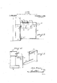
Figure 1 is a perspective of the improved ventilator;
Fig. 2 is a top plan thereof showing the same engaged with a window frame;
Fig. 3 is a vertical transverse section therethrough Fig. 4: is a fragmentary end elevation Specificationiof fatent.
showingthe mounting of the ventilatoranchoringmeans; and i a I Fig. 5-is a detail in perspective of one of the anchoringmeans. l
Similar characters of reference are employed in allof the above described views to: indicate corresponding parts.
several figures of thesaid drawings, there is provided a substantially rectangular housing designated 1, the front ofwhich is openl Laterally oifset flanges 5 "andG are formed upon the housing adjacent the open front wall thereof and as will be noted, the flange-6 is provided with an upwardly bent portion -6 the said portion being arranged QR-efer'ring-now more; specifically to the in spaced-relation to the body of the flange,
thus, providing an eflicient' way, the purpose of -which iwill' -be subsequently apparent. Thetop 'ofthe housing l 'is substantially open and hasformed-u-pon its marginal edges laterally projecting flanges 7 and-8,
the-flanges 7 being'provided with depending portions which are adapted to serve as bearings-forthe} air regulating'means, which will be subsequently described. "Intermedi- "atethe endeof the housing a partitio1r9'is 4 arranged.
To the fianges'5, anchoring means comprising sheet metal elements 10 having horizontal slots 11 formed therein are secured through the medium of rivets 12 or like fastening devices passing through the said flanges into engagement with the horizontal slots 11. Fingers 13 are formed uponthe lower portions of the anchoring element'll and are slidably received within the ways formed by the upturned portion of the flange 6 as designated by the reference character 6. Obviously, by so mounting the anchoring element upon the flanged ends of the housing construction, the same may be adjusted laterally thereof in order that the ventilator may be adapted to window frames varying in Iwidth.
A plurality of-slats 14: are extended longitudinally of the housing top and have their opposite extremities journaled inthe depending portions of the flanges 7 and the longitudinally alined openings formed in the partition 9. The bearing pintles as engaged in the openings formed in the partiwire and are bent intermediate their ends to provide crank portions 15. A bar 16 1.
having 'a plurality of vertically disposed slots 17 formed therein is slidably arranged within the partition 9,- tlfe'outer extremity'- thereof beingreduced and provided with a V series of notches 18 engageable over the lower portion of the opening in the rear wall' of the housing througlf'which the" said redueed portion extends, and havinga handle- 19 formed on its outer end. The vertically disposed; slots are arranged over the; crank portions of the slot bearing-pintles and by shifting the positioningof: the; bar 16 a may be moved to'causerelative vadjustment of:thesaid--slats To preventiundu'e vertica'limovernent of-the bar a projection 20 is arranged upon;theunderside of the upper or-top wall I of the partition I 9 and ;normally bears upon the adjacent marginaledge of the=baT-.- K, v
In?operation the ventilator housing-f1 is arrangeduponthesillof the window frame, the-flange;Gabuttingthe usual shoulder as formed"thereon, .thus;v preventing undue-lateral V movement-- or displacement thereof. The slidable sash; is now moved into I lower position whereupon the" same will; be engaged with thenpperiportions of the anchoring; elements '10 thus; locking the housingjin, position and al'lowingsuflicientspace to permit the ingress of-airinto the housing.
To regulate the *flbwofainthrough the housing; into the room} or building, the relative I positioning' of: the pivoted slats may; be
varied by; shiftinggthe bar 16 to causeoscil lation' off'the crank-- portion 1 :15; Should? it be necessa-ry; the anchoring elements 10 may be adjusted laterally of the housing 1 to permit the" firmengagement of the same with the window frame.
In this connection, itisto be understood that various forms of connections may be employed in lieu of the riv'ets'12 'for locking the anehoringelements 10 in adjusted positions. v
I claim:
1. A ventilator, includinga-housing having an openfront wall and flanges formed on the ends and bottomsthereof, anchoring means adjustably mounted' on said-end flanges, a partition arranged intermediate theends of the housing, a plurality-oflongitudinally disposed slats rotatably mounted in the housing ends and said partition,
cranks engaged with the adjacent-endsof said slats, and an adjustable bar movable in the partition and loosely engaged with said crank for causing movement of the slats.
2; A ventilator including ahousing haV- ing an open front wall; anchoring means on the ends thereof a plurality of slats V rotataoARL' EVANS.
Priority Applications (1)
| Application Number | Priority Date | Filing Date | Title |
|---|---|---|---|
| US156703A US1352257A (en) | 1917-03-22 | 1917-03-22 | Ventilator |
Applications Claiming Priority (1)
| Application Number | Priority Date | Filing Date | Title |
|---|---|---|---|
| US156703A US1352257A (en) | 1917-03-22 | 1917-03-22 | Ventilator |
Publications (1)
| Publication Number | Publication Date |
|---|---|
| US1352257A true US1352257A (en) | 1920-09-07 |
Family
ID=22560689
Family Applications (1)
| Application Number | Title | Priority Date | Filing Date |
|---|---|---|---|
| US156703A Expired - Lifetime US1352257A (en) | 1917-03-22 | 1917-03-22 | Ventilator |
Country Status (1)
| Country | Link |
|---|---|
| US (1) | US1352257A (en) |
-
1917
- 1917-03-22 US US156703A patent/US1352257A/en not_active Expired - Lifetime
Similar Documents
| Publication | Publication Date | Title |
|---|---|---|
| US3830146A (en) | Ventilator control system | |
| US1352257A (en) | Ventilator | |
| US1874083A (en) | Ventilating device | |
| US1915994A (en) | Damper | |
| US1217225A (en) | Window-ventilator. | |
| US2123751A (en) | Ventilator | |
| US2134143A (en) | Ventilator | |
| US345692A (en) | Geoege hayes | |
| US780247A (en) | Ventilating cornice or strip. | |
| US1696922A (en) | Ventilator opener | |
| US2265881A (en) | Louver | |
| US1890758A (en) | Ventilator | |
| US1014058A (en) | Ventilator for houses. | |
| US3027823A (en) | Awning vent window | |
| US955991A (en) | Ventilating-register. | |
| US2309354A (en) | Combined screen and ventilator | |
| US327414A (en) | Ventilator | |
| US2623251A (en) | Adjustable louver for venetian blinds | |
| US516860A (en) | Window-ventilator | |
| US584890A (en) | Window-ventilator | |
| US814888A (en) | Hot-air register. | |
| US1061096A (en) | Device for operating blinds of window-shutters. | |
| US231548A (en) | Window-awning | |
| US254884A (en) | Ventilator | |
| US1696105A (en) | Combined box base and damper |