US1345016A - Telephone system - Google Patents
Telephone system Download PDFInfo
- Publication number
- US1345016A US1345016A US246234A US24623418A US1345016A US 1345016 A US1345016 A US 1345016A US 246234 A US246234 A US 246234A US 24623418 A US24623418 A US 24623418A US 1345016 A US1345016 A US 1345016A
- Authority
- US
- United States
- Prior art keywords
- selector
- switches
- relay
- cord
- telephone system
- Prior art date
- Legal status (The legal status is an assumption and is not a legal conclusion. Google has not performed a legal analysis and makes no representation as to the accuracy of the status listed.)
- Expired - Lifetime
Links
- 238000004804 winding Methods 0.000 description 5
- 239000004020 conductor Substances 0.000 description 4
- 238000010276 construction Methods 0.000 description 3
- 230000000881 depressing effect Effects 0.000 description 2
- 229930091051 Arenine Natural products 0.000 description 1
- 241000518994 Conta Species 0.000 description 1
- 241000896693 Disa Species 0.000 description 1
- 208000025814 Inflammatory myopathy with abundant macrophages Diseases 0.000 description 1
- 150000001450 anions Chemical class 0.000 description 1
Images


Classifications
-
- H—ELECTRICITY
- H04—ELECTRIC COMMUNICATION TECHNIQUE
- H04Q—SELECTING
- H04Q3/00—Selecting arrangements
- H04Q3/42—Circuit arrangements for indirect selecting controlled by common circuits, e.g. register controller, marker
Definitions
- HUNDREDS THOUSANDS i lnven/ors v A/ben E Lundel/ flank/in A. Sfearr' A. E. LU NDELL AND F. A.- STEARN.
- GROUP OFF/CE BRUSH //7 venfors. A/ben f. L undefl flank/fl? ,4. Sfearn by A? A. E. LUNDELL AND F. A. STEARN.
- trolling system in which a plurality. of sendl h sett ngpf selec ively UNITED STATES PATENT OFFICE.
- This invention relates to electrical controlling systems and particularly to electrical controlling systems for automatic and semi-automatic telephone exchanges.
- T he object of the present invention is to reduce and simplify the impulse controlling units provided in automatic and semi-automatic telephone systems for the control of selector switches.
- one of the objects of this invention is to provide improved and more efficient circuit arran ements to accomplish the features disc osed in a coendin application to A. E. Lundell, erial o. 139,511, filed December29, 1916.
- a portion ofthe present invention may be defined as .relating to anelectrical cons0 "'wh,”
- invention contemplates the .useof acontrolling device at each of a plurality of operators positions, a plurality of sender's-common to the Improvec etm an he plurality of operators positions, and a plurahty of automatic switches -individual to each operators position for associating the controlling device thereat with an idle sender.
- a plurality of pairs of automatic switches are provided at each operators position to establish a connection between the cord circuits thereat and an idle sender, and means are provided individual to each pair of switches for connecting the controlling device at the operators position to the sender through only one of the switches of each pair.
- Another feature of the invention is .the rovision of means whereby if either one o the switches of a pair of switches used in establishing a connection between the cord circuits and an idle sender fails to operate properly, both switches are released and another pair of switches are automatically started to establish the desired connection.
- Another feature is the prowision of a line relay which is common to a plurality of switches.
- the line relays which control the operation of the district selectors are. in the sender selector circuits which are common to a plurality of district selectors.
- i si disas s is which sava ed; mac- :91.
- difier t appara Ac ordiiisk o, t is fee.
- the selector switches used in this system are of the so-called power driven type, described. in Patent No. 1,123,696 to E. B. Craftv and J. N. Reynolds issued Jan. 5, 1915.
- District selector Fig. 1
- ofiice selector 2 local incoming selector
- Fig. 3 final selector
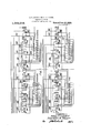
- Fig. 4 sender selector
- Each of the selector switches has a vertically movable brush rod carrying brushes arranged to wipe over a commutator plate and thus control the operation of the respective selector switch.
- Each rod also carries brushes which are arranged to engage contacts of aterminal bank, by means 0 which connections to lines leading to switches or to I subscribers stations. may be established.
- the terminal bank of the district, oflice, local incoming, and final selectors comprise 500 rows of terminals divided into five sections of one hundred rows of terminals each.
- Each set of brushes is arranged to engage any row of terminals ina certain section, and normally w rests below the first row of the terminals of each respective section.
- the brushes of a set are normally held apart by means'of a cam whereby they are out of the path of the terminals.
- sequence switches with the exception of sequence switch 300 shown in the present disclosure are of the type described in Patent No. 1127,808, issued Feb. 9, 1915, to fteynolds and Chas. "F. Baldwin. Sequence switches 10, 100, 150 and 200 control by means of their contacts, the circuits of the district, ofiice, local incoming and final selectors respectively.
- the sequence switch 900 controls the circuits of an operators keyboard; sequence switch 500 controls the circuits of a plurality of registers, sequence switch 700- controls the circuits of a sender, and sequence switch 800 also controls the operation of the sender and will be referred to as a class register.
- the sequence switch 300 is of substantially the same construction as that' dis closed in the above mentioned Patent 1,127 808 except that instead of being driven by a constantl rotating drum it is moved step by step y v an operating magnet and any well knowng-ratchet and pawl arrangement.
- each of the cord finders A and B and the allotter 400 is substantially the same as that disclosed in the above mentioned Patent 1,127,808.
- each'row with the exception of the 0, co and station keys, comprises keys numbered from zero to nine, each key controlling as many contacts as is necessary for'controllin the selectors and registers.
- the number 0 ofiice keys depends upon the traflic requirements.
- saaoae oih ce keys are the equivalent of the tandem hundreds, tens and units of the keys; that is, the depression of one ofiice key is the equivalent of the depression of a combination of tandem hundreds, tandem tens and tandem units keys.
- the ofiice keys are provided for controlling theseizure of trunks leading to important offices, whereas other ofiices may be reached by depressing a desired combination of tandem keys.
- Figs. 12, 15 and 16 represent ten registers. These registerswi-ll be referred to as district brush, district group, ofiice brush, oflice- General arrangement of the impulse controlling apparatus.
- the present invention is designed to be used in a telephone exchange system employing a plurality of operators positions. Associated with each operators position there are a plurality of cord circuits, one end of each cord circuit terminating in an answering plug and the other end in a district selector. A single keyboard is also provided at each operatorsposition. Common to all the operators positions there are a plurality of senders and associated with each sender is a set of registers.
- a group of link circuits is provided at each operators position.
- One end of each of these link circuits terminates in a'sen'der selector which is arranged to select an idle sender whenever the link circuit associated therewith is taken for use.
- the otherfend of each link circuit terminates in a plurality of different cord finders, each of which has access to different cord circuits.
- the link circuit shown in Figs. 8 and 9 terminates in cord finder A which is one of a plurality of cord finders having access to twelve cordsof a total of twentyfour cords; and it also terminates in cord finder B which is one of a plurality of cord finders having access to the other twelve cords of an operators position.
- a relay is associated with each link circuit whereby the operators keyboard, which is common to a particular group of link circuits, can be connected to the link circuit when it is taken for use.
- An allotter is associated with each grolp of link circuits so as to always have an i e circuit preselected.
- the arrangement of the trunk terminals of the various sections of the terminal banks of the district and olfice selectors depends upon the trafiic requirements, and in the present case, it will be assumed that the in coming selector shownin Fig. 3 is accessible in response to the-depression of the A office key which controls the tripping of the third set of brushes of'the district selector, the stepping of these brushes on to the ninth group of terminals in the third sectionof the terminal bank, and then the tripping of the second set ofbrushes in the office selector and the setting of these brushes on, to the first group ofvterminals in the second section of the terminal bank of the office selector.
- the trunks which terminate in this group lead to final selectors which'have access to lines numbered 3000 to 3499.
- the local incoming selector is then operated to select an idle trunk in this group.
- the fifthset of brushes of the final selector will then be positioned below the sixth group of terminals in which terminate lines numbered 3450--3460.
- the brushes of the final selector will finally be moved into engagement with the seventh set of terminals of the sixth group, thereb completing the connection to the desired ine.
- the manual exchange is reached by means of the district and office selectors or by trunks leading directl from the district selector to the manual 0 ce. Then a call indicator at said manual exchange will be operated in a well known manner to inform the operator thereatgofi, 380
- substation 201 removes his receiver from the switchhook, whereupon the line relay 2 becomes energized and causes the lighting of the calling lamp 3.
- the operator inserts the plug 4 into the jack 5 associated with the calling line and a circuit is closed from grounded battery, winding of cut-oil relay 6, sleeve of 'ack 5, sleeve of plu 4 and the winding 0% rela 7 to ground.
- lelay 6 becomes energize opens the circuit of relay 2, whereupon lamp 3 isextinguished.
- Relay 7 becomes energized and closes a circuit from grounded battery,
- a circuit is completed from grounded -batter ,power magnet of se uence switch 425 (o cord finder A WlllCl has access to a group of cord circuits comprising the particular cord circuit shown), lower contact of sequence switch spring 426, sequence switch spring 901, conductor 902, contact of spring 451 controlled by sequence switch 450 of cord finder B, conductor 401, lower left-hand contact of spring 402 of allotter 400, conductor 403, right-hand contact of sequence switch spring 16, outer right-hand armature and front contact of relay 15, conductor 17, lower left-hand contact of sequence switch spring 18 to ground. Sequence switch 425 thereupon moves out of position 17 and into position 18.
Landscapes
- Engineering & Computer Science (AREA)
- Computer Networks & Wireless Communication (AREA)
- Structure Of Telephone Exchanges (AREA)
- Exchange Systems With Centralized Control (AREA)
- Keying Circuit Devices (AREA)
- Sub-Exchange Stations And Push- Button Telephones (AREA)
Priority Applications (10)
| Application Number | Priority Date | Filing Date | Title |
|---|---|---|---|
| NL10705D NL10705C (ref) | 1918-07-22 | ||
| NL8539D NL8539C (ref) | 1918-07-22 | ||
| NL8540D NL8540C (ref) | 1918-07-22 | ||
| US246234A US1345016A (en) | 1918-07-22 | 1918-07-22 | Telephone system |
| FR510985A FR510985A (fr) | 1918-07-22 | 1919-07-21 | Système électrique de controle pour bureaux centraux téléphoniques |
| GB14590/20A GB143908A (en) | 1918-07-22 | 1919-07-22 | Telephone exchange system |
| GB13813/20A GB143551A (en) | 1918-07-22 | 1919-07-22 | Telephone exchange system |
| GB18233/19A GB130329A (en) | 1918-07-22 | 1919-07-22 | Telephone Exchange System. |
| FR22908A FR22908E (fr) | 1918-07-22 | 1920-03-27 | Système électrique de controle pour bureaux centraux téléphoniques |
| FR22909A FR22909E (fr) | 1918-07-22 | 1920-03-27 | Système électrique de controle pour bureaux centraux téléphoniques |
Applications Claiming Priority (1)
| Application Number | Priority Date | Filing Date | Title |
|---|---|---|---|
| US246234A US1345016A (en) | 1918-07-22 | 1918-07-22 | Telephone system |
Publications (1)
| Publication Number | Publication Date |
|---|---|
| US1345016A true US1345016A (en) | 1920-06-29 |
Family
ID=22929842
Family Applications (1)
| Application Number | Title | Priority Date | Filing Date |
|---|---|---|---|
| US246234A Expired - Lifetime US1345016A (en) | 1918-07-22 | 1918-07-22 | Telephone system |
Country Status (4)
| Country | Link |
|---|---|
| US (1) | US1345016A (ref) |
| FR (3) | FR510985A (ref) |
| GB (3) | GB143908A (ref) |
| NL (3) | NL8539C (ref) |
-
0
- NL NL10705D patent/NL10705C/xx active
- NL NL8540D patent/NL8540C/xx active
- NL NL8539D patent/NL8539C/xx active
-
1918
- 1918-07-22 US US246234A patent/US1345016A/en not_active Expired - Lifetime
-
1919
- 1919-07-21 FR FR510985A patent/FR510985A/fr not_active Expired
- 1919-07-22 GB GB14590/20A patent/GB143908A/en not_active Expired
- 1919-07-22 GB GB13813/20A patent/GB143551A/en not_active Expired
- 1919-07-22 GB GB18233/19A patent/GB130329A/en not_active Expired
-
1920
- 1920-03-27 FR FR22908A patent/FR22908E/fr not_active Expired
- 1920-03-27 FR FR22909A patent/FR22909E/fr not_active Expired
Also Published As
| Publication number | Publication date |
|---|---|
| NL8540C (ref) | |
| NL8539C (ref) | |
| FR510985A (fr) | 1920-12-14 |
| GB143908A (en) | 1920-10-22 |
| FR22909E (fr) | 1921-09-06 |
| GB130329A (en) | 1920-10-22 |
| FR22908E (fr) | 1921-09-06 |
| GB143551A (en) | 1920-10-22 |
| NL10705C (ref) |
Similar Documents
| Publication | Publication Date | Title |
|---|---|---|
| GB550235A (en) | Improvements in telephone systems | |
| US1345016A (en) | Telephone system | |
| US2299212A (en) | Telephone system | |
| US2376346A (en) | Telecommunication system | |
| US2088942A (en) | Quotation system | |
| GB636920A (en) | Improvements in or relating to automatic telephone systems | |
| US1601052A (en) | Telephone-exchange system | |
| US1509691A (en) | Multioffice telephone system | |
| US2773127A (en) | Calling line identification apparatus | |
| US2372353A (en) | Telephone system | |
| US1795350A (en) | Service observation in telephone systems using call indicators | |
| US2672520A (en) | Telephone system for private automatic business exchanges | |
| US1709084A (en) | Number-indicating system | |
| US2562362A (en) | Testing system employing test distributor switches and test connector switches | |
| GB617932A (en) | Improvements in telephone switching systems | |
| US1767959A (en) | Automatic telephone-exchange system | |
| US2347107A (en) | Switching system | |
| US1504258A (en) | Telephone-exchange system | |
| US1618423A (en) | Telephone-exchange system | |
| US1559244A (en) | Telephone-exchange system | |
| US1594877A (en) | Telephone system | |
| US1859475A (en) | Call indicator system | |
| US1648009A (en) | Machine-switching selector-switch | |
| US1695043A (en) | Telephone-exchange system | |
| US1639135A (en) | Telephone system |